OFFICINE OROBICHE 20 Series User manual

OFFICINE OROBICHE
S.p.A.
1/4
INSTRUCTION MANUAL FOR LEVEL SWITCHES
SERIES 20 Electric
24010 Ponteranica (Bergamo) ITALY
-
via Serena, 10
-
Tel. 0039/035/4530211
-
Fax 0039/035/570546
-
www.officineorobiche.it
-e-
mail:[email protected]
******************************************************************************************************************************************************************
JULY ’0
5
Information subject to changes without prior notice
IST/099
-I
1. DESCRIPTION OF THE ITEM
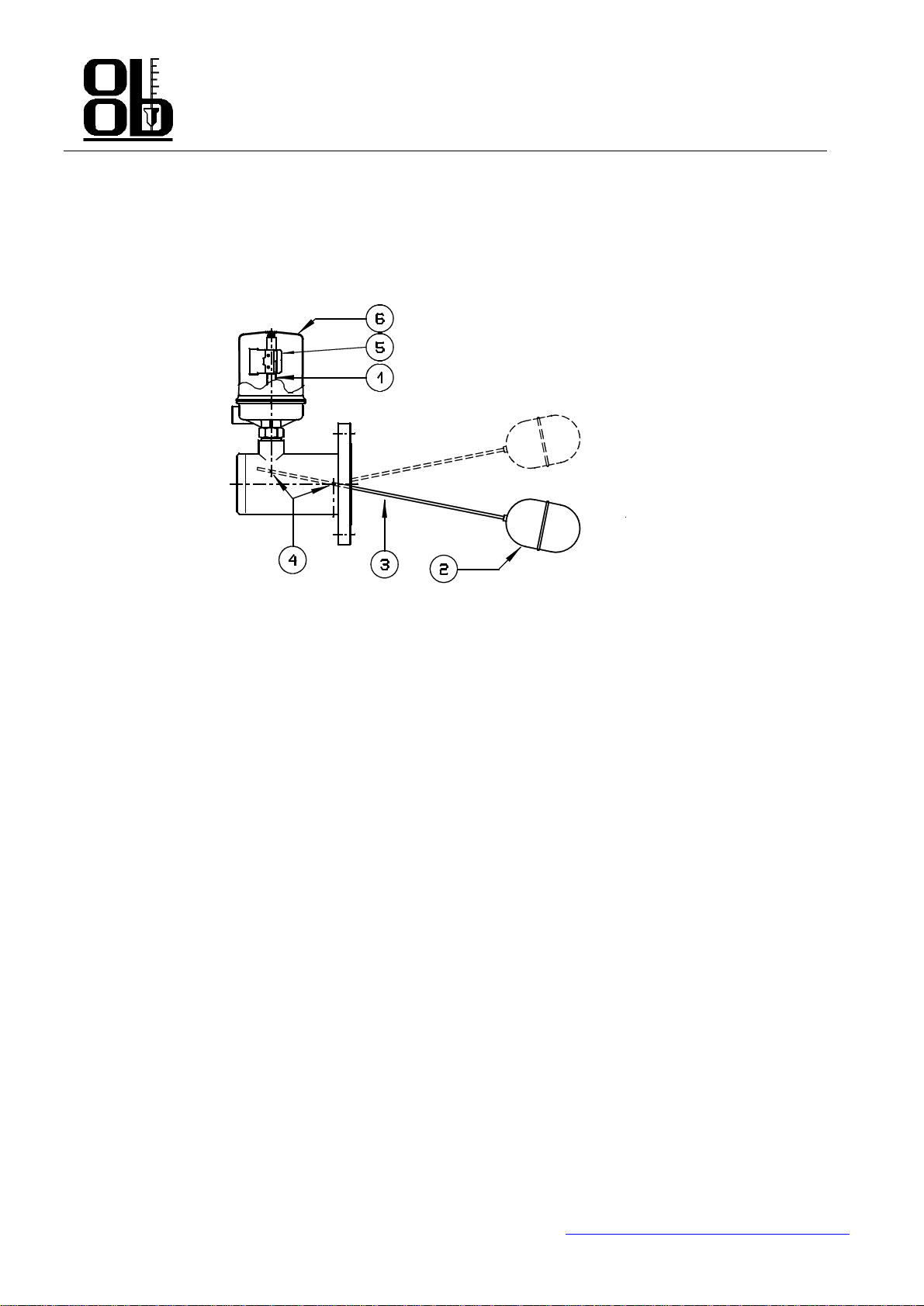
Level switches model 20 have been conceived on the basis of lever principle and designed to be assembled on the side of
pressure containers.
Connections can be both threaded and flanged.
Operation rod starting succeeds by means of hydrostatic power and force of gravity; both operate in the same direction
and the opposite way. Their resultant makes the float (2) placed on the end of the lever arm (3) inside the pressure
recipient translate upright. The other lever arm end (3) is
fully inside the item body and controls one or two electric switch
groups placed inside the external sheath (6) by means of a connection rod moving system and a magnet starting. The
external sheath (6) can be water
-
tight or deflagration
-
tight.
2. MODEL D
EFINITION
Model definition is available in all our general catalogues.
All the items we supply are always to be identified by means of a serial number placed on the item identification plate.
Such plate is firmly secured on the item head.
3. FUNCTIONING P
RINCIPLE
The agency of hydrostatic power is a function both of the float volume and of the fluid specific mass and also and of the
level value. It can fluctuate from zero [float (2) completely uncovered] up to a maximal value [float (2) completely
dipped].
The latter value must be bigger than the one due to the system weight in order to grant the functioning even in the
presence of friction and attractive / repulsive magnetic forces. The resultant force represents the item margin.
Every item is distinguis
hed by two margins.
1-
gradient margin (hydrostatic power
-
force of gravity);
2-
descent margin (force of gravity).
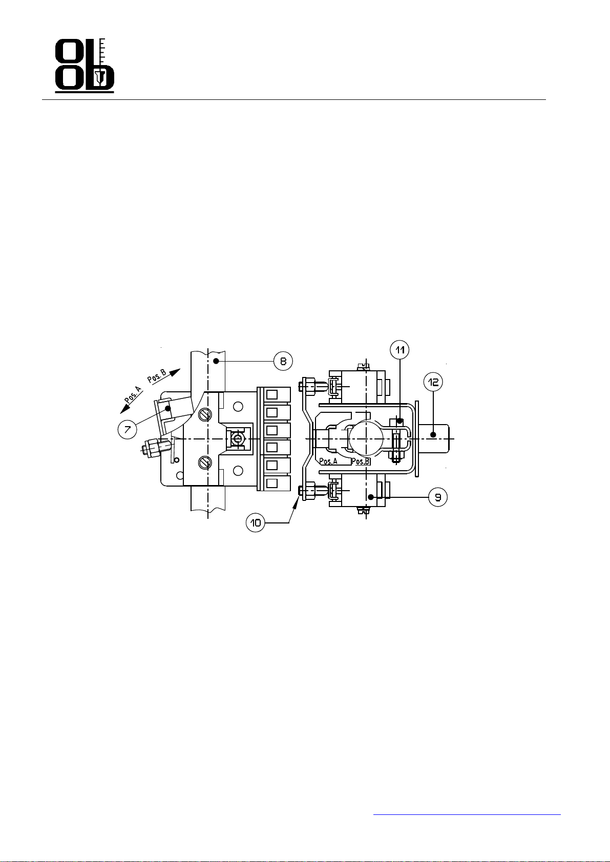
A connecting rod is secured on the operating lever arm opposite to the float (2) end bearing on the top a “magnetic
anchor” (1). Such anc
hor (1) can only move upright inside a “sump” made of anti
-
magnetic material (stainless steel). The
sump head is closed and separates the item section under process pressure from the section under atmospheric pressure.
Thickness is calculated according to
ASME VIII div. 1. No stuffing box nor mechanical seal exist. When the anchor (1)
rises or lowers, it reaches a magnet (7) field outside the sump, mechanically connected to one or two electric
microswitches.
The magnet, together with the microswitches, for
m the “switch group” also called “release unit (5)”.
Maximum two release units can be assembled on every item; functioning takes place at two different fluid level values.
When the magnetic field power between anchor (1) and release unit (5) is bigger than
the gravitational component
maintaining the release unit open, magnet (7) translation and consequent microswitches change
-
over succeeds (release).
When, during a further movement of the anchor (1), the gravitational component becomes bigger than the m
agnetic field
power, a back translation to the original magnet (7) position takes place, together with another consequent microswitches
change
-
over (disjunction). Release and disjunction points are not coincident because of the internal hysteresis inside t
he
item. Such item hysteresis is called “release differential”.
4. INSTALLATION
SET UP ON THE PLANT
- The installation point on the tank shall be far enough from any obstacle compromising the space necessary for
disassembly. Float (2) inside the tank shall be placed in an area free from any liquid turbulence. In case this won’t be
possible, protections will be provided in order to eliminate the mentioned turbulence.
- Always make sure the connection pipe is properly dimensioned, both in diameter and in length before installing the
item [float (2) has to go into the tank]; moreover, make sure the pipe is perfectly horizontal (max. 0.5° inclination) and
has max. 1° misalignment.
-
Level switch (7) is based on a functioning principle suffering the effects of c
onsiderable shaking and vibrations.

OFFICINE OROBICHE S.p.A.
2/4
24010 Ponte
ranica (Bergamo) ITALY -
via Serena, 10
-
Tel. 0039/035/4530211
-
Fax 0039/035/570546
-
www.officineorobiche.it
-e-
mail:[email protected]
******************************************************************************************************************************************************************
JULY ’05
Information subject to changes without prior notice
IST/099
-I
WIRING HARNESS
-
The item is equipped with one or two connecting terminal boxes placed inside the sheath (5).
-
The terminal box (12) is equipped with terminals where external connections are cabled.
Indications NC
-
C
-
NO listed on the terminal box (12) refer to the whole item, not to the single microswitch (9) and
refer to the lack of liquid condition.
-
Make sure the sheath cover (6) is well closed before turning the power on.
5. SET UP
-
Make
sure the use doesn’t exceed the allowed limits (higher pressures and temperatures, lower specific weight) and
also that the electrical rating is the proper one as indicated on the rating plate.
-
Make sure the item carries out the commuting operation corr
ectly, making the liquid level fluctuate several times.
6. CALIBRATION
The item has been calibrated in the factory and doesn’t need any kind of adjusting on site.
7. MAINTENANCE
We suggest a periodic inspection (approximately every 6 months) granting the
full working order of the item at the time
of the installation. Checking is simple and quick; we have two kinds: inspection of the body/float and of the release unit.
ATTENTION
-
NEVER open the cover before making sure power has been turned off.
-
NEVER l
eave the sheath (6) uncovered after inspection
-
NEVER use the item with pressures and temperatures higher than the ones indicated on the rating plate.
-
NEVER use the item with electrical rating higher than the one indicated on the rating plate.
-
NEVER a
djust or replace parts without first reading with the utmost attention the instruction manual. In case of doubt,
please refer to our Customer’s Assistance Service.
-
NEVER grease item’s components.
-
When using items having high temperature, always accompl
ish all necessary precautions in order to grant workers
safety.
PERIODICAL INSPECTION ON THE FLOAT
-
Periodically clean the float (2) and make sure no encrustation or dirt exist between rod and fulcrum support (4),
hindering the free movement of the float.
PERIODICAL INSPECTION ON THE CONNECTIONS
-
During item disassembly for cleaning and maintenance, make sure microswitch (9) carries the commutation out
correctly moving float (2) manually.

OFFICINE OROBICHE S.p.A.
3/4
24010 Ponte
ranica (Bergamo) ITALY -
via Serena, 10
-
Tel. 0039/035/4530211
-
Fax 0039/035/570546
-
www.officineorobiche.it
-e-
mail:[email protected]
******************************************************************************************************************************************************************
JULY ’05
Information subject to changes without prior notice
IST/099
-I
REPLACEMENT OF RELEASE UNIT AND MICROSWITCH
- When You need to remove the release unit for replacement, use a gauge to take note of the original position and
grant the correct repositioning once the operations are over.
-
For microswitch (9) replacement please act as follows:
a-
make sure the item is disconnected
b-
take note of the exact release unit by means of a gauge.
c-
disconnect the clamps (take note of their original positioning ), remove the release unit unlocking screw (11).
d-
replace the microswitch (9)
e-
reassemble the release unit on pipe (8) exactly i
n the previous position as shown in point “b”
f-
adjust release as follows:
Push magnet unit (7) manually against pipe (8), turn the calibration grain (10) until microswitch (9) releases.
Please foresee an over stroke of grain (10) after release.
g- verify the full working order of microswitch (9) By means of an ohm-meter. Test the microswitch (9) release
manually for a couple of times.
h-
connect the wires again to the connection terminal box as described in point 7c.
SWITCH GROUP
ADJ
USTING OF THE INTERVENTION POINT
-
Release unit has been positioned in the factory during calibration and following checking on the required intervention
point. The original position shall normally not be changed.
-
Take note of the original position by m
eans of a gauge in case release unit should be removed to allow microswitch
(9) replacement, and/or complete release unit replacement so as to grant correct repositioning once operations are
over.
-
In case You should by mistake not take note of the origi
nal position, please act as follows:
a-
bring the fluid level to the required point
b-
slowly lower the release unit until the magnet unit (7) turns from position B towards the pipe (8) and the commuted
switch.
c-
if the required release is foreseen for lo
w level, lock release unit in that position by means of screw (11).
d-
if the required release is foreseen for high level, slowly rise the unit until the magnet unit (7) comes back to position
A. Lock release unit in that position by means of screw (11)

OFFICINE OROBICHE S.p.A.
4/4
24010 Ponte
ranica (Bergamo) ITALY -
via Serena, 10
-
Tel. 0039/035/4530211
-
Fax 0039/035/570546
-
www.officineorobiche.it
-e-
mail:[email protected]
******************************************************************************************************************************************************************
JULY ’05
Information subject to changes without prior notice
IST/099
-I
8. DAMAGES LOCALIZATION
Level switches model 20 have been conceived with no defect and meant for long lasting.
In case the level switch wouldn’t signal any emergency, we suggest to check the release unit and further the float (2) as
mentioned in the p
aragraph on preventive maintenance.
In case the defect isn’t to be found out even after all regular checking, please refer to our Customer’s Assistance
Service.
9. ELIMINATION
Once functioning cycle is over and whenever wreaking will be taken into consid
eration, items elimination shall comply
to all directives existing in the place of installation as well as in the place of final elimination.
What above regards in particular polymeric, resins and gums eventually used during manufacturing (PVC, PTFE, PP,
PVDF, neoprene, viton, non
-
asbestos joints etc.). All metal components deprived of seals, special protective coverings
required by the customer and any other plastic component are recyclable.
ATTENTION
In case the installed microswitches have mercury bulb,
their elimination shall comply the existing directives as regards
toxic and hurtful materials. All other microswitches don’t contain toxic materials.
10. WARRANTY
Level switches model 20 are granted for any functioning and material defect for 5 years fro
m delivery date. In case of
misfunctioning, with return, within the above mentioned limit, or in case the damage cause is covered by the warranty,
the Officine Orobiche will do all necessary (item replacement also) without debiting any charge to the custom
er,
transport charges excluded.
The OFFICINE OROBICHE won’t be responsible for the eventual misuse of the item or for uses different from the ones
listed in the order specifications and accepted by the producer. Otherwise no complaint will be accepted. Dam
ages
and/or expenses, both direct and indirect, coming from an unproper installation or use shall not be in any case debited to
OFFICINE OROBICHE.
The item shall be used for a maximum period of 10 years from delivery time. After that period two alternative
s are
possible:
1) Subject the item to inspection at Officine Orobiche with the help of a specialized technician, taking upon himself the
responsibility of further use;
2) Replace the item with a new one.
FINAL NOTES
Any item is supplied fully assembled a
nd complete with all the required equipment. Only in special cases some parts
will be supplied separately. We beg You to always check Your supply with the utmost attention and to immediately
notify eventual discordance.
Always mention the serial number of
the item when inquiring for some spare parts. This number is to be found on the
rating plate secured on the sheath (6). The number is composed of 5 figures preceded by letter “F” (ex. F45678).
N.B.
IN CASES WHEN THE INSTRUMENTS ARE MEANT TO BE USED IN AREAS FEATURING
POTENTIALLY EXPLOSIVE ATHMOSPHERES, THE USER SHALL COMPLY WITH THE ADDITIONAL
SAFETY INSTRUCTIONS
ATTACHED TO THE STANDARD ONES.
Table of contents
Other OFFICINE OROBICHE Switch manuals
Popular Switch manuals by other brands

NETGEAR
NETGEAR EN104TP EN104TP EN104TP installation guide

Level
Level GEP-2622 Series user manual

Captron
Captron CANEO SR Series Original operating instructions

Weil-McLain
Weil-McLain SlimFit 383-600-513 manual

Cisco
Cisco Catalyst 1800 Guide manual

Generac Power Systems
Generac Power Systems TTS Series owner's manual

Oracle
Oracle Sun Datacenter InfiniBand Switch 648 installation guide

Emerson
Emerson AVOCENT Installer/user guide

Alcatel-Lucent
Alcatel-Lucent 060321-10, Rev. B Cli reference guide

Cisco
Cisco CSS 11501 - Content Services Switch Getting started guide

ATEN
ATEN AS-251S user manual

Freedom9
Freedom9 freeView IP 800 user manual