Elsner Remo KNX RF Guide

Remo KNX
Remote Control
Item number 70747
EN
Installation and Ad justment


1 Content
Elsner Elektronik GmbH • Sohlengrund 16 • 75395 Ostelsheim • Germany
Radio remote control Remo KNX RF • from software version 1.3, ETS programme version 2.0
Status: 15.01.2019 • Technical changes and errors excepted.
1. Description ........................................................................................... 5
1.1. Deliverables .............................................................................................................. 6
1.2. Technical specifications ........................................................................................... 6
1.3. Notes on wireless equipment ................................................................................. 6
2. First use/set-up ..................................................................................... 7
2.1. Loading the battery, transport block ...................................................................... 7
2.2. Protective film ........................................................................................................... 7
2.3. Set-up procedure ...................................................................................................... 7
3. Using the remote control ..................................................................... 8
3.1. Automatic switch-off ................................................................................................ 8
3.2. Display ....................................................................................................................... 8
3.3. Operating drives and devices .................................................................................. 8
3.3.1. Control media ................................................................................................ 8
3.3.2. Moving drives (Up/Down) ............................................................................ 9
3.3.2.1. Buttons: ......................................................................................... 10
3.3.2.2. Sliders: ........................................................................................... 10
3.3.3. Switching devices (on/off) .......................................................................... 10
3.3.4. Dimming ...................................................................................................... 11
3.3.4.1. Buttons: ......................................................................................... 11
3.3.4.2. Sliders: ........................................................................................... 11
3.3.5. RGB(W) lights .............................................................................................. 11
3.3.5.1. On/off buttons: .............................................................................. 12
3.3.5.2. Sliders: ........................................................................................... 12
3.3.6. Lights with adjustable colour temperature ............................................... 13
3.3.6.1. Buttons: ......................................................................................... 13
3.3.6.2. Sliders: ........................................................................................... 13
3.3.7. Changing temperature ............................................................................... 13
3.3.7.1. Buttons: ......................................................................................... 14
3.3.7.2. Sliders: ........................................................................................... 14
3.3.8. Scenes ......................................................................................................... 14
3.3.9. Measured value view .................................................................................. 14
4. Care and maintenance ....................................................................... 15
4.1. Troubleshooting ..................................................................................................... 15
5. Channel setting in the ETS ................................................................. 16
5.1. Transfer protocol .................................................................................................... 16
5.2. System .................................................................................................................... 18
5.3. Media page ............................................................................................................. 18
5.4. Channel activation .................................................................................................. 20
5.5. Channel 1...8 ........................................................................................................... 20
5.5.0.1. Display type: .................................................................................. 21
5.5.0.2. Input type – Switching: ................................................................. 21
5.5.0.3. Input type – Dimming: .................................................................. 22

2 Content
Elsner Elektronik GmbH • Sohlengrund 16 • 75395 Ostelsheim • Germany
Radio remote control Remo KNX RF • from software version 1.3, ETS programme version 2.0
Status: 15.01.2019 • Technical changes and errors excepted.
5.5.0.4. Input type – RGB/RGBW: .............................................................. 22
5.5.0.5. Input type – Colour temperature: ................................................ 23
5.5.0.6. Input type – Shutter: ..................................................................... 24
5.5.0.7. Input type – Blinds, awnings: ....................................................... 25
5.5.0.8. Input type – Window: ................................................................... 26
5.5.0.9. Input type – Temperature: ............................................................ 26
5.5.0.10.Input type – Scene: ....................................................................... 27
5.5.1. Control modes for drive control ................................................................ 28
6. Remote control programming ............................................................ 29
7. Remote control set-up ........................................................................ 30
7.1. Display ..................................................................................................................... 30
7.2. Wireless channel configuration ............................................................................ 31
7.2.1. Changing channel name ............................................................................ 31
7.2.2. Text for feedback ........................................................................................ 32
7.2.3. Text for on/off .............................................................................................. 33
7.2.4. Changing channel order ............................................................................. 34
7.3. System .................................................................................................................... 34

3 Clarification of signs
This manual is amended periodically and will be brought into line with new software
releases. The change status (software version and date) can be found in the contents footer.
If you have a device with a later software version, please check
www.elsner-elektronik.de in the menu area "Service" to find out whether a more up-to-
date version of the manual is available.
Clarification of signs used in this manual
Installation, inspection, commissioning and troubleshooting of the device
must only be carried out by a competent electrician.
Safety advice.
Safety advice for working on electrical connections, components,
etc.
DANGER! ... indicates an immediately hazardous situation which will lead to
death or severe injuries if it is not avoided.
WARNING! ... indicates a potentially hazardous situation which may lead to
death or severe injuries if it is not avoided.
CAUTION! ... indicates a potentially hazardous situation which may lead to
trivial or minor injuries if it is not avoided.
ATTENTION! ... indicates a situation which may lead to damage to property if it is
not avoided.
ETS In the ETS tables, the parameter default settings are marked by
underlining.

4 Clarification of signs

5Description
Remote Control Remo KNX RF • Version: 15.01.2019 • Technical changes and errors excepted.
1. Description
The colour touchscreen of Remote Control Remo KNX RF can be used to manually to
control bus participants in the KNX system. Remo KNX RF uses the KNX RF S standard.
The possible functions are
•Switch
•Dimm
• Move the drives of awnings, shutters, blinds or windows
• Change the temperature (for heating/cooling)
• Change RGBW light colour
• Change light colour temperature
• Call and save scenes
• Operate media equipment
• Indicate bus values (e.g. status, sensor values).
The channels are set in the ETS. However, they can be individually sorted and named on
the display.
Functions:
• Operation via the touch display
• Lithium battery, chargeable via a USB-2.0 Micro-B charger (Charger No 10155 as an
optional accessory). Battery level status and a warning at <20% battery charge can
be sent via the bus
• 32 channels, wireless standard KNX RF, S-Mode
• The touch buttons can be named individually, directly on the device or in the ETS
• The display sequence can be changed directly on the device
• Setting functions on the display can be locked (and unlocked) via the application
and the bus
Configuration is made using the KNX software ETS 5. The product file can be downloaded
from the ETS online catalogue and the Elsner Elektronik website on www.elsner-elektro-
nik.de in the “Service” menu.
If communication with wired KNX devices (KNX TP) is necessary, a media coupler that con-
nects KNX RF and KNX TP is needed (e.g. KNX RF LC-TP No 70710).
ATTENTION!
Radio transmission takes place on a non-exclusive transmission
path!
The device is not suitable for applications in the field of safety engineering, e.g.
emergency stop, emergency call.
Moisture is harmful to the electronic components of the remote
control. You must therefore:
• Not leave it in the rain
• Not leave it outside overnight
• Protect it from frost

6Description
Remote Control Remo KNX RF • Version: 15.01.2019 • Technical changes and errors excepted.
1.1. Deliverables
• Wireless remote control with integrated battery
• USB cable 0.5 m (USB-A plug to USB-B micro plug)
1.2. Technical specifications
The product is compliant with the provisions of EC guidelines.
1.3. Notes on wireless equipment
When planning facilities with devices that communicate via radio, adequate radio reception
must be guaranteed. The range will be limited by legal regulation and structural circum-
stances. Avoid sources of interference and obstacles between receiver and transmitter, that
could disturb the wireless communication. Those would be for example:
• Walls and ceilings (especially concrete and solar protection glazing).
• Metal surfaces next to the wireless participants (e. g. aluminium construction of a
conservatory).
• Other wireless devices and powerful local transmitters (e.g. wireless headphones),
which transmit on the same frequency. Please maintain a minimum distance of 30
cm between wireless transmitters for that reason.
Housing Plastic
Colour black
Protection category IP 40
Dimensions approx. 64 x 122 x 11 (B x H x T, mm)
Display colour TFT, capacitive, dimmable,
resolution 320 x 480 Pixel
Weight approx. 100 g
Ambient temperature operating 0…50 °C, storage -10…+60 °C
Ambient humidity max. 95 % RH, avoid condensation
Operating voltage integrated battery 3.8 V DC
Wireless frequency 868.2 MHz
Channels 32
Data output KNX RF (S-Mode)
BCU Type own micro controller
PEI Type 0
Group addresses max. 512
Assignments max. 1024
Communication objects 417

7First use/set-up
Remote Control Remo KNX RF • Version: 15.01.2019 • Technical changes and errors excepted.
2. First use/set-up
2.1. Loading the battery, transport block
First, charge the integrated battery of the remote control with a standard commercial USB
charging device (USB 2.0 Micro B connector). Charging will reset the transport block that is
active on delivery. The remote control can be used only once it is connected to the power
supply via the charging cable.
If necessary, the transport block can be reactivated within the System menu (see manual,
chapter System).
The charge level of the battery and a warning if the level is under 20% can be sent via the
bus. Battery charge level and low-battery warning (bus notification). See manual, System
chapter.
The battery of the device cannot be removed or replaced. When disposing of the device,
observe the guidelines for disposing of devices with an integrated battery.
2.2. Protective film
Remove the protective film from the display.
2.3. Set-up procedure
1. Required: Configuration of the channels in the ETS (version 5 and later).
See manual, chapter Setting the channels in the ETS.
2. Required: Programming the device
See manual, chapter Programming the remote control.
3. Optional: Change the names and the channel sequence in the wireless channel config-
uration menu.
See manual, chapter Wireless channel configuration.
Charging
socket
Battery charging status indicator

8Using the remote control
Remote Control Remo KNX RF • Version: 15.01.2019 • Technical changes and errors excepted.
3. Using the remote control
3.1. Automatic switch-off
The display of the remote control switches on when the device is moved (e.g. if the remote
control is picked up) and switches off again after several seconds to save energy. The time
until switch-off can be set in the Display menu (see Chapter 3.2. Display, page 8).
3.2. Display
The display shows all channels one after another. The sequence can be changed in the
Wireless channel configuration > Change channel order menu (see manual, Chapter
Change channel order). Keep in mind that access to these setting menus can be locked.
Locking/unlocking can be done via the ETS application or the bus (communication object).
If more than five drives/devices are taught, the display uses several pages to show them.
Use the Up/down arrow buttons to change page.
3.3. Operating drives and devices
3.3.1. Control media
e.g. music, film
The operating options available depend on the selection in the ETS. The following functions
are available:
Display view during first set-up
With multiple-page views, the media control can be ac-
cessed via the small button at the top right of Page 1.
If the view has only one page, the media page can be
opened via its own button.

9Using the remote control
Remote Control Remo KNX RF • Version: 15.01.2019 • Technical changes and errors excepted.
3.3.2. Moving drives (Up/Down)
Shutter, blind, awning or window
Back to remote control view (Page 1)
Switch device on
Switch device off
Switch device on/off (combined view)
Device is off (combined view)
Device is on (combined view)
Update
Previous title
Display title information, album, interpret
Next title
Previous playlist
Playlist view
Next playlist
Repeat
Play
Pause
Play/Pause (combined view)
Shuffle (play the titles in random order)
Higher
Mute
Lower

10 Using the remote control
Remote Control Remo KNX RF • Version: 15.01.2019 • Technical changes and errors excepted.
‘Buttons’ and ‘sliders’ can be activated as operating interfaces in the ETS. If multiple inter-
faces are active, you can switch between the views using the right area of the bar (side sym-
bol ).
Buttons:
Tap on the up or down arrow to position the drive.
The reaction of the buttons to the short tap/longer holding, as well as the display of the po-
sition, depends on the settings in the ETS.
The position of the drive is shown in the button, left of the symbol, if the ‘Feedback’ setting
was activated in the ETS. With shutters, the slat position can also be displayed (right side
of the symbol).
Sliders:
Shift the point on the line to position the drive. If ‘feedback’ is activated in the ETS,
then the current curtain height will be displayed in %, and the position of the point on the
line will correspond to the current curtain position as soon as feedback is received.
In case of shutters, a second slider can be activated in the ETS for the slat position ( ).
ETS settings, see manual, Chapter Channel 1...8, sections about shutters, blinds, awnings
or windows.
3.3.3. Switching devices (on/off)
Tapping the right side of the bar switches the device on. Tapping the left side of
the bar switches the device off. The buttons can be provided with a label, in the ETS,
in the menu Wireless channel configuration > On/Off text (see manual, Chapter Changing
the On/Off Text).
If the ‘Feedback’ setting is activated in the ETS, the status reported by the bus (text, on/yel-
low symbol or off/grey symbol) is displayed. Otherwise, there is no feedback for the status.
The feedback text can be changed in the ETS in the menu Wireless channel configuration >
Feedback text (see manual, Chapter Changing the Feedback Text).
For ETS settings, see manual, Chapter Channel 1...8, section Switching.

11 Using the remote control
Remote Control Remo KNX RF • Version: 15.01.2019 • Technical changes and errors excepted.
3.3.4. Dimming
‘Buttons’ and ‘sliders’ can be activated as operating interfaces in the ETS. If multiple inter-
faces are active, you can switch between the views using the right area of the bar (side sym-
bol ).
Buttons:
A shorter tap on + switches on, tapping on - switches off.
A longer tap on + adjusts the light to a brighter setting, holding -, to a darker set-
ting. If you release the key, the brightness stops changing.
The time interval between short and long and other parameters are set in the ETS. If the
‘Feedback’ setting is activated in the ETS, the status reported by the bus (on/yellow symbol
or off/grey symbol) is displayed. Otherwise, there is no feedback for the status.
The dimming percentage is shown in the button, left of the symbol, if the ‘Feedback’ setting
was activated in the ETS.
Sliders:
Shift the point on the line to dim the lights. If ‘feedback’ is activated in the ETS, then
the current brightness will be displayed in %, and the position of the point on the line will
correspond to the current brightness as soon as feedback is received.
For ETS settings, see manual, Chapter Channel 1...8, section Dimming.
3.3.5. RGB(W) lights
To set individual light values for red, green, blue and white, use the buttons to switch the
lights on/off, and three (RGB) or four (RGBW) sliders to adjust the colour.
These functions can all be placed on a single channel (i.e. one bar). In this case, you can
switch between the functions using the right area of the bar (side symbol ). However, the
functions can be distributed over multiple channels, so that switching and colour control
can be carried out via multiple adjacent bars. The configuration takes place in the ETS.
Sending settings to the lights:
Depending on the settings, the changes on the RGBW sliders will be sent directly to the
lights, or the settings will only be sent if you remain on the right button (on) longer.

12 Using the remote control
Remote Control Remo KNX RF • Version: 15.01.2019 • Technical changes and errors excepted.
On/off buttons:
Tapping the right side of the bar switches the device on. Tapping the left side of
the bar switches the device off. The buttons can be provided with a label, in the ETS,
in the menu Wireless channel configuration > On/Off text (see manual, Chapter Changing
the On/Off Text).
If the ‘Feedback’ setting is activated in the ETS, the status reported by the bus (text) is dis-
played. Otherwise, there is no feedback for the status. The feedback text can be changed in
the ETS in the menu Wireless channel configuration > Feedback text (see manual, Chapter
Changing the Feedback Text).
Colour view:
The current colour setting is shown in a box on the bar; the representation on the display
can deviate severely from the actual light colour.
RGB luminaire without feedback: 1 box
RGBW luminaire without feedback: 2 boxes
RGB luminaire with feedback: 2 boxes
RGBW luminaire with feedback: 4 boxes
Sliders:
set
RGB mixed value
set
RGB mixed value
set
white calue
RGB
feedback value
set
RGB mixed value
RGB
feedback value
set
RGB mixed value
white
feedback value
set
white value

13 Using the remote control
Remote Control Remo KNX RF • Version: 15.01.2019 • Technical changes and errors excepted.
Shift the point on the line to change the light colour with the red, green, blue and
white parameters. The colour bar on the left shows the colour; the representation on the
display can deviate severely from the actual light colour.
If ‘feedback’ is activated in the ETS, then the current brightness will be displayed in %, the
position of the point on the line will correspond to the current brightness, and the colour
bar will update as soon as feedback is received.
For ETS settings, see manual, Chapter Channel 1...8, section RGBW.
3.3.6. Lights with adjustable colour temperature
‘Buttons’ and ‘sliders’ can be activated as operating interfaces in the ETS. If multiple inter-
faces are active, you can switch between the views using the right area of the bar (side sym-
bol ).
Buttons:
Holding + switches the device on; holding - switches the device off.
Tapping + makes the light colder; tapping -, warmer.
The time interval between short and long and other parameters are set in the ETS. If the
‘Feedback’ setting is activated in the ETS, the colour temperature value reported by the bus
(colour field red (warmer light), blue (colder light) and Kelvin value) is displayed. Otherwise,
there is no feedback for the status.
Sliders:
Shift the point on the line to change the colour temperature. If ‘feedback’ is activat-
ed in the ETS, then the current colour temperature will be displayed in Kelvins (K), and the
position of the point on the line will correspond to the current colour temperature as soon
as feedback is received.
The colour bar on the right indicates the colour tendency towards warm or cold with red-
dish, white or bluish colours.
For ETS settings, see manual, Chapter Channel 1...8, section Colour temperature.
3.3.7. Changing temperature
Adjusting heating or cooling
‘Buttons’ and ‘sliders’ can be activated as operating interfaces in the ETS. If multiple inter-
faces are active, you can switch between the views using the right area of the bar (side sym-
bol ).

14 Using the remote control
Remote Control Remo KNX RF • Version: 15.01.2019 • Technical changes and errors excepted.
Buttons:
Tap+ to increase the target temperature.
Tap- to reduce the target temperature.
The current target temperature is shown in the button, left of the symbol, if the ‘Feedback’
setting was activated in the ETS (always for temperature objects). The way the temperature
change takes place is set in the ETS.
Sliders:
Shift the point on the line to change the temperature. If ‘feedback’ is activated in the
ETS, then the current target temperature will be displayed in C° as soon as feedback is re-
ceived.
For ETS settings, see manual, Chapter Channel 1...8, section Temperature.
3.3.8. Scenes
Each scene button is used to control two scenes: The left button half for one, and the right
button half for the other scene.
Tap a button half for a short time to call the scene.
Holding it longer saves the scene in the current state (e.g. movement position, dimming
level etc.), provided this function was activated in the ETS.
For ETS settings, see manual, Chapter Channel 1...8, section Scene.
3.3.9. Measured value view
A bar can be used as a display area for values from the bus system. Actions not possible.
For ETS settings, see manual, Chapter Channel 1...8.

15 Care and maintenance
Remote Control Remo KNX RF • Version: 15.01.2019 • Technical changes and errors excepted.
4. Care and maintenance
Please carefully clean the remote control with a damp cloth. Do not use detergent.
4.1. Troubleshooting
Problem: The display is off, the remote control does not react:
Problem: The display is on, the device/drive does not react to button presses:
Problem: Menu cannot be accessed (the menu does not appear if the upper bar is swiped
from the top downwards):
Cause Procedure
Transport block active Please connect the remote control to the power supply using
a charging cable. This deactivates the lock.
Battery not charged Please connect the remote control to the power supply using
a charging cable to charge the battery. The charge status is
shown with the battery symbol at the top right corner of the
operation pages.
Cause Procedure
Wireless contact has been lost,
transmitter is too far away from
the receiver
Choose another location
No voltage to receiver unit or
faulty receiver unit
Switch on the receiver unit (e.g. the control unit). Should
wireless contact still not be established, please contact
Customer Service
Cause Procedure
Menu locked Unlock the menu in the ETS application or via the correspon-
ding communication object

16 Channel setting in the ETS
Remote Control Remo KNX RF • Version: 15.01.2019 • Technical changes and errors excepted.
5. Channel setting in the ETS
5.1. Transfer protocol
Abbreviations:
RRead
WWrite
C Communication
T Transfer
UUpdate
No Text Function Flags DPT type Size
1 System: Block settings
(0: block,1: unblock)
Input RWCT [1.3] DPT_Enable 1 Bit
2 System: Low battery Output R-CT [1.2] DPT_Bool 1 Bit
3 System: Battery charge [%] Output R-CT [5.4] DPT_Per-
cent_U8
1 Byte
Media page (Objects 10-32)
10 Media: On/off Output --CT [1.1] DPT_Switch 1 Bit
11 Media: Off Output --CT [1.1] DPT_Switch 1 Bit
12 Media: On/off feedback Input -WCT [1] 1.xxx 1 Bit
13 Media: Playback Output --CT [1.1] DPT_Switch 1 Bit
14 Media: Pause Output --CT [1.1] DPT_Switch 1 Bit
15 Media: Playback feedback Input -WCT [1.1] DPT_Switch 1 Bit
16 Media: Increase/decrease volume Output --CT [3] 3.xxx 4 Bit
17 Media: Volume [%]
Feedback
Input -WCT [5.4] DPT_Per-
cent_U8
1 Byte
18 Media: Volume [%] Output --CT [5.1] DPT_Scaling 1 Byte
18 Media: Next title Output --CT [1] 1.xxx 1 Bit
20 Media: Previous title Output --CT [1] 1.xxx 1 Bit
21 Media: Current title Input -WCT [16] 16.xxx 14 Bytes
22 Media: Current artist Input -WCT [16] 16.xxx 14 Bytes
23 Media: Current album Input -WCT [16] 16.xxx 14 Bytes
24 Media: Next playlist Output --CT [1] 1.xxx 1 Bit
25 Media: Previous playlist Output --CT [1] 1.xxx 1 Bit
26 Media: Current playlists Input -WCT [16] 16.xxx 14 Bytes
27 Media: Shuffle Output --CT [1.1] DPT_Switch 1 Bit
28 Media: Repeat Output --CT [1.1] DPT_Switch 1 Bit
29 Media: Mute Output --CT [1.1] DPT_Switch 1 Bit
30 Media: Shuffle feedback Input -WCT [1] 1.xxx 1 Bit
31 Media: Repeat feedback Input -WCT [1] 1.xxx 1 Bit

17 Channel setting in the ETS
Remote Control Remo KNX RF • Version: 15.01.2019 • Technical changes and errors excepted.
32 Media: Mute feedback Input -WCT [1] 1.xxx 1 Bit
Channel 1 (Objects 35-46)
35 Channel 1: Left display Input -WCT Depending on
setting
14 Bytes
36 Channel 1: 2 A Input -WCT [5.10] DPT_Val-
ue_1_Ucount
1 Byte
37 Channel 1: 3 A Input -WCT [5] 5.xxx 1 Byte
38 Channel 1: 4 A Input -WCT [5] 5.xxx 1 Byte
39 Channel 1: 5 A Input -WCT [5] 5.xxx 1 Byte
40 Channel 1: 6 A Input -WCT [5] 5.xxx 1 Byte
41 Channel 1: Right display Input -WCT Depending on
setting
4 Bytes
42 Channel 1: 2 B Input -WCT [5] 5.xxx 1 Byte
43 Channel 1: 3 B Input -WCT [5] 5.xxx 1 Byte
44 Channel 1: 4 B Input -WCT [5] 5.xxx 1 Byte
45 Channel 1: 5 B Input -WCT [5] 5.xxx 1 Byte
46 Channel 1: 6 B Input -WCT [5] 5.xxx 1 Byte
Channel 17 (Objects 227-238) see Channel 1
Channel 2 (Objects 47-58) see Channel 1 Channel 18 (Objects 239-250) see Channel 1
Channel 3 (Objects 59-70) see Channel 1 Channel 19 (Objects 251-262) see Channel 1
Channel 4 (Objects 71-82) see Channel 1 Channel 20 (Objects 263-274) see Channel 1
Channel 5 (Objects 83-94) see Channel 1 Channel 21 (Objects 275-286) see Channel 1
Channel 6 (Objects 95-106) see Channel
1
Channel 22 (Objects 287-298) see Channel 1
Channel 7 (Objects 107-118) see Channel
1
Channel 23 (Objects 299-310) see Channel 1
Channel 8 (Objects 119-130) see Channel
1
Channel 24 (Objects 311-322) see Channel 1
Channel 9 (Objects 131-142) see Channel
1
Channel 25 (Objects 323-334) see Channel 1
Channel 10 (Objects 143-154) see Chan-
nel 1
Channel 26 (Objects 335-346) see Channel 1
Channel 11 (Objects 155-166) see Chan-
nel 1
Channel 27 (Objects 347-358) see Channel 1
Channel 12 (Objects 167-178) see Chan-
nel 1
Channel 28 (Objects 359-370) see Channel 1
Channel 13 (Objects 179-190) see Chan-
nel 1
Channel 29 (Objects 371-382) see Channel 1
No Text Function Flags DPT type Size

18 Channel setting in the ETS
Remote Control Remo KNX RF • Version: 15.01.2019 • Technical changes and errors excepted.
5.2. System
Set the menu block and battery information.
System menu:
The system menu can be blocked/unblocked via Object 1. With the menu blocked, no ad-
justments (e.g. name, sequence) can be introduced in the device.
Battery:
Set if the battery charge or a notification of low battery charge (under 20%) should be trans-
mitted via the bus. The information is sent on initialisation, i.e. when the display switches
on (automatically when you take the device in your hand).
5.3. Media page
Set up page for media control
Activate the media equipment page.
Activate the necessary operating functions and operate the sent and feedback values.
On/off:
Channel 14 (Objects 191-202) see Chan-
nel 1
Channel 30 (Objects 383-394) see Channel 1
Channel 15 (Objects 203-214) see Chan-
nel 1
Channel 31 (Objects 395-406) see Channel 1
Channel 16 (Objects 215-226) see Chan-
nel 1
Channel 32 (Objects 407-418) see Channel 1
Block/unblock the system menu via a bit
object
No • Yes
Send the bit object after initialisation if the
battery charge is under 20%
No • Yes
Send the battery charge value after initiali-
sation
No • Yes
Use media equipment page No • Yes
Use play/pause No • Yes
Use separate symbols • No
• Yes
Sending for on 0 • 1
Sending for off 0 • 1
Return value for on 0 • 1
No Text Function Flags DPT type Size
Table of contents
Other Elsner Remote Control manuals
Popular Remote Control manuals by other brands
Skytech
Skytech CON1001TH-1 Installation and operating instructions
One Forall
One Forall 6-DEVICE PVR user guide
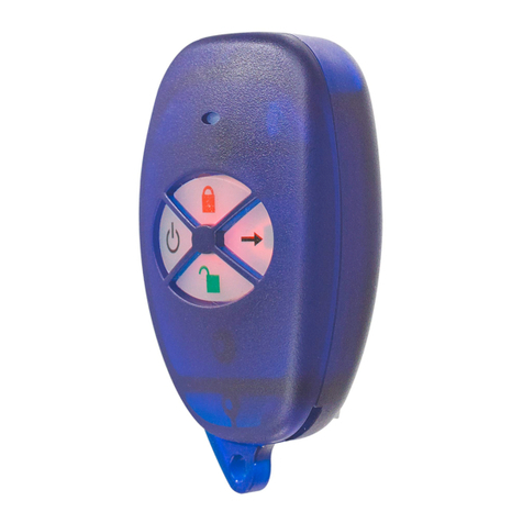
Paradox
Paradox Magellan MG-RAC1 instructions
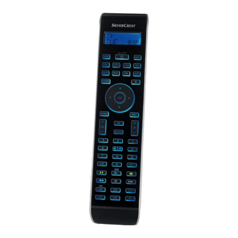
Silvercrest
Silvercrest SFB 10.1 B2 operating manual
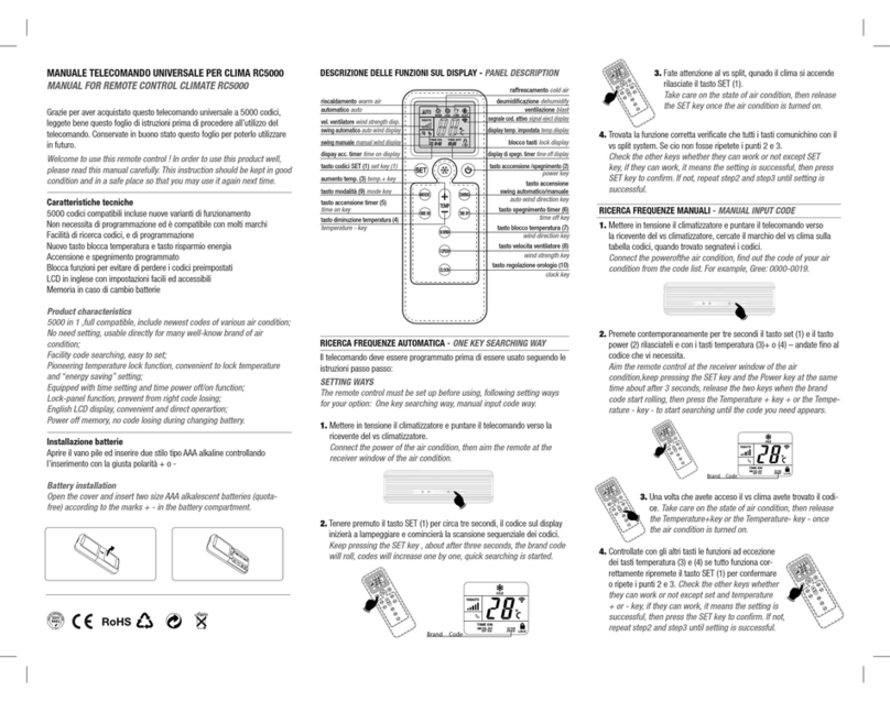
smart home
smart home Climate RC5000 instruction manual

LIVARNO LUX
LIVARNO LUX 373084-2204 Operation and safety notes
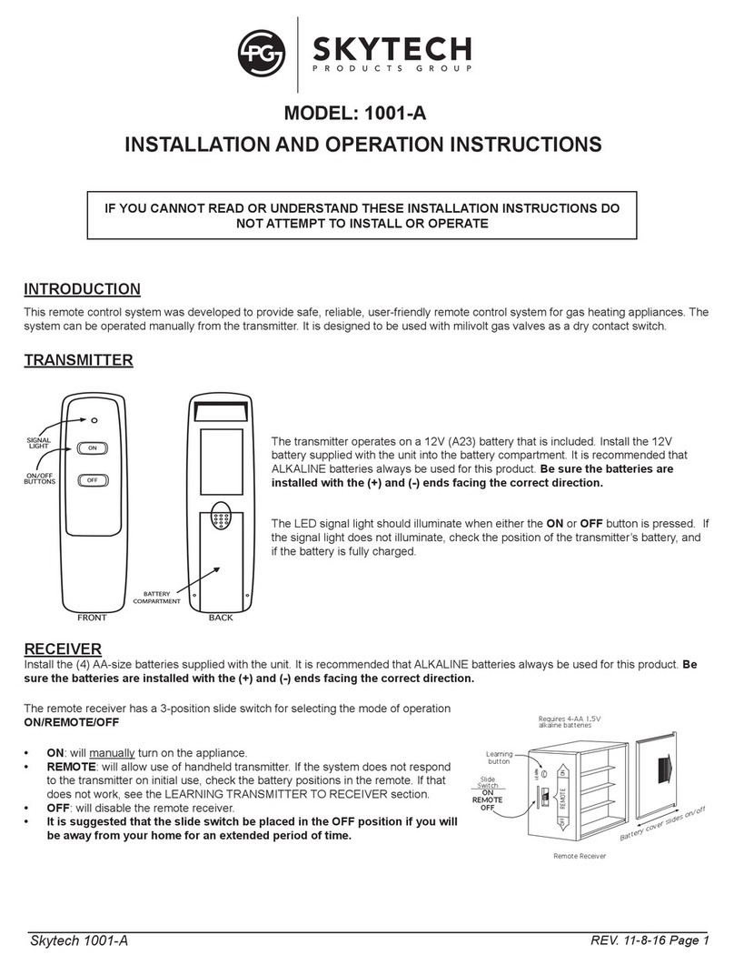
Skytech
Skytech 1001-A Installation and operation instructions
Skytech
Skytech CON 1001-1 Installation and operating instructions
Real Fyre
Real Fyre RR-2A Installation and operating instructions
One Forall
One Forall URC-7110 manual
Skytech
Skytech 1410-A Installation and operation instruction
eControls
eControls Smart WHF Control WTTK Installer manual


