eControls Smart WHF Control WTTK User guide

WHF
Smart
C o n t r o l
Jan 2020
ON/OFF
MODE
SPEED
HON
SetCool To
SPEED
Indoors
WHF
Smart
CAUTIONS
Use cautions when mounting components to surfaces that
may have concealed wiring beneath the surface.
Turn off power before installing whole house fan or controls.
Read and follow all instructions carefully, including those
included with the whole house fan. Read entire manual
before installing products.
Follow all local electrical codes during installation. All wiring
must conform to local and national electrical codes.
Installation should be performed by a qualified individual
with sufficient experience and skill.
!
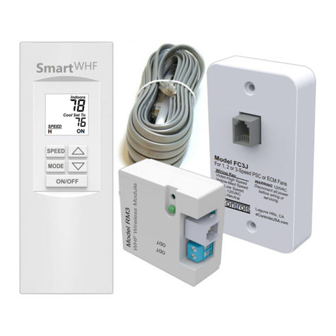
The WTTK kit includes a WTT Whole House Fan Wall
Control, an FC3J Fan Control and a 50’ plug&play cable.
The optional TS3J Outdoor Temperature Sensor can be
added to the installation to delay fan operation if the
outdoor temperature is too warm to provide cooling.
When servicing WHF controls, turn off all power to these
items.
Step 3. Install a Plastic Retrofit Gang Box
INSTALLER MANUAL
Model WTTK
Whole House Fan Wall Control
Laguna Hills, CA
eControlseControls
Model FC3J
eControlsUSA.com
For 1, 2 or 3-Speed PSC or ECM Fans
WARNING 120VAC.
Disconnect all power
before wiring or
servicing.
Violet-High Speed
Yellow-Med Speed
Red-Low Speed
Black-120VAC
White-Neutral
Wiring Key
Wire the FC3J to the fan using the diagram below as a guide. If
the FC3J fan control is already installed on the fan, go to Step 2.
Step 1. Install FC3J in Junction Box on Fan
Connect to FAN High
Speed Wire
Connect to FAN Low
Speed Wire
Connect to FAN Medium
Speed Wire
Connect to POWER
120VAC Wire
Connect to FAN Neutral
Wire and to POWER
120VAC Neutral Wire
LS
MS
HS
120
VAC
NTL
Low Speed
Medium Speed
High Speed
120VAC Power
Neutral
Unused wires should be cut at the
PCB or capped with wire nuts.
!
Laguna Hills, CA
eControls
eControls
Model FC3J
eControlsUSA.com
For 1, 2 or 3-Speed PSC or ECM Fans
WARNING
120VAC.
Disconnect all
power before wiring
Violet-High Speed
Yellow-Med Speed
Red-Low Speed
Black-120VAC
White-Neutral
Wiring Key
Use the screws included to secure the
FC3J to the junction box on the fan
making sure there are no exposed
wires and the fan control is securely
inside the electrical box. Failure to do
so could result in electrical shock.
The WTT is installed in a plastic retrofit
single gang box in the sleeping space on a
wall about 5’ off the floor in a location that
will best sense the temperature for the
space. Do not install in a location where
the temperature will be influenced such as
in direct sunlight, on an exterior wall, etc.
Do not install WTT in a metal gang box.
Step 2. Connect Cable to the FC3J
Connect one end of the “RED” Plug&Play cable into the FC3J
fan control already installed on the junction box on the fan.
Feed this end
to the gang box
Insert into FC3J
already installed
on fan.
See FC3J Wiring Diagrams on pages 3-4 for wiring to
fans manufactured by QC Manufacturing.
i

Attach the WTT wall control to the plastic gang box using the
screws provided. Attach the wall plate to the WTT using the
screws provided in the wall plate.
Step 7. Attach the WTT and Wall Plate
Connect the other end of the “RED” Plug&Play cable into
the”RED” connector on the back of the WTT wall control.
Connect to
“RED”
connector on
back of WTT
Step 5. Connect Cable to the WTT
For a 2-Speed fan, PRESS then PRESS to
lower the fan speed to Low (L). PRESS then
PRESS to return to High (H) Speed.
PRESS then PRESS to select
TEMPERATURE CONTROL.
Step 9. Checking the Installation
PRESS to turn the fan ON. Fan should be running.
ON/OFF
PRESS then press to select TIMER CONTROL.
MODE
Verify that the fan is running in High speed. For a 3-Speed fan,
PRESS then PRESS to lower the fan speed
to Medium (M). PRESS then PRESS to lower
the fan speed to Low (L). PRESS then PRESS
to return to High (H) speed.
SPEED
CHECK FAN OPERATION
CHECK FAN SPEEDS
SPEED
SPEED
SPEED
SPEED
RETURN TO TEMPERATURE CONTROL
MODE
ON/OFF
PRESS to turn the fan OFF.
Step 4. Feed Cable to Gang Box
If the optonal TS3J Outdoor Temperature Sensor is
being installed, install it now. (See the TS3J Installer
Guide.)
Feed the other ends of the cable from
the FC3J and the TS3J (if installed)
through the wall and the opening in the
gang box. Insert the gang box into the
wall opening and secure.
i
If a sensor is installed, connect the cable with the “YELLOW”
marker into the “YELLOW” connector.
Step 6. Power the Fan
Apply power to the fan. If the fan automatically starts up,
remove power and check the wiring. If the problem persists,
contact us.
Verify that the WTT Wall Control LCD is displaying, indicating
the the WTT is receiving power.
Step 8. Set the Number of Fan Speeds
The WTT is factory set to a two speed fan. For three-speed or
one-speed fan installations, the number of fan speeds available
needs to be changed to reflect the type of fan installed.
To change the number of speeds, PRESS and HOLD
until the first option is displayed. PRESS again to
display the number of speeds. PRESS to set a 3-speed
fan or PRESS to set a 1-speed fan.
MODE
MODE

Power Wiring
Safety
Cautions - Be sure to follow all codes in your locality.
Ground Wiring
Unused Wires
All green or bare copper ground wires should be tied
together and to the ground screw in the bottom of the
electrical box on the Fan.
Be sure to cap any unused wire from the FC3J with
smaller blue wire nuts.
Use AWG14 Romex cable or a heavy duty (15A) power
cord to power the Fan.
Be sure all power to the Fan is OFF beore attempting
any wiring.
!
LS
MS
HS
115
VAC
NTL
LS
MS
HS
115
VAC
NTL
WD-01, 1-Speed PSC Fan WD-02, 2-Speed PSC Fan
115VAC
Power
115VAC
Power
High Speed High Speed
Ground Ground
Fan Fan
Power Power
Screw Screw
Electrical box
on the Fan.
Electrical box
on the Fan.
FC3J Control FC3J Control
115VAC 115VAC
Neutral Neutral
Low Speed
Use the tables below to determine which wiring diagram to wire the Fan and Power to the FC3J. The wire colors used by the Fan
manufacturer for high, medium and low speed vary with fan models. The model number is on a label on the Fan.
FC3J Wiring Diagrams for fans manufactured by QC Manufacturing.
Tri Pro-1.5X
Tri Pro-2.5X
Tri Pro-3.3X
Tri Pro-4.8X
Tri Pro-5.5X
Tri Pro-6.0X
Tri Pro-7.0X
Model #
TRIDENT PRO Series
, PSC MotorRed Fan
One
Two
Two
Two
Two
Two
Two
Speeds
WD-01
WD-02
WD-02
WD-02
WD-02
WD-02
WD-02
Wiring Diagram
ES-1500
ES-2250
ES-3100
ES-4700
ES-5400
ES-6000
ES-7000
Model #
ENERGY SAVER Series
, ECM MotorGreen Fan
One
Two
Two
Two
Two
Two
Two
Speeds
WD-03
WD-04
WD-06
WD-06
WD-06
WD-06
WD-06
Wiring Diagram
STL Pro 1.5X
STL Pro 2.5X
STL Pro 3.3X
STL Pro 4.8X
STL Pro 5.5X
STL Pro 6.0X
STL Pro 6.7X
Model #
STEALTH PRO Series
Black Fan, ECM Motor
One
Two
Two
Three
Three
Three
Three
Speeds
WD-03
WD-04
WD-06
WD-05
WD-05
WD-05
WD-05
Wiring Diagram
CL-1500
CL-2250
CL-3100
CL-4700
CL-5400
CL-6000
CL-7000
Model #
CLASSIC Series
, PSC MotorBlue Fan
One
Two
Two
Two
Two
Two
Two
Speeds
WD-01
WD-02
WD-02
WD-02
WD-02
WD-02
WD-02
Wiring Diagram
3

LS
MS
HS
115
VAC
NTL
LS
MS
HS
115
VAC
NTL
LS
MS
HS
115
VAC
NTL
LS
MS
HS
115
VAC
NTL
WD-03, 1-Speed ECM Fan WD-04, 2-Speed ECM Fan
WD-06, 2-Speed ECM FanWD-05, 3-Speed ECM Fan
115VAC
Power
115VAC
Power
115VAC
Power
115VAC
Power
High Speed High Speed
High SpeedHigh Speed
Med Speed
Low Speed
Low Speed
Low Speed
Ground Ground
GroundGround
Fan Fan
FanFan
Power Power
PowerPower
Screw Screw
ScrewScrew
Electrical box
on the Fan.
Electrical box
on the Fan.
Electrical box
on the Fan.
Electrical box
on the Fan.
FC3J Control FC3J Control
FC3J ControlFC3J Control
115VAC 115VAC
115VAC115VAC
Neutral Neutral
NeutralNeutral
*Black wire from fan motor may be
solid black or black with white stripe.
*Black wire from fan motor may be
solid black or black with white stripe.
*Black wire from fan motor may be
solid black or black with white stripe.
*Black wire from fan motor may be
solid black or black with white stripe.
26072 Merit Circle #110 / Laguna Hills, CA 92653
949-916-0945 Fax 949-458-8502
www.eControlsUSA.com
Warranty
This thermostat is warranted to be free of defects due to workmanship
or materials under normal use and service for a period of 5 years from
date of installation and not longer than 6 years from manufacturing
date code.
eControlseControls
Ensure that the cable is completely plugged into the “RED”
connector on the WTT and the FC3J. You should hear the
connectors click. Ensure that the fan is powered. Ensure the
wiring from the FC3J fan control to the whole house fan is
correct.
Ensure that the number of speeds set in Step 7 correspond to
the type of fan installed - 1-speed, 2-speed or 3-speed fan.
The WTT LCD is not lit.
Fan speeds available is not correct.
TROUBLESHOOTING
If On is not blinking and the WTT is in Temperature Control,
make sure the Set To temperature is a few degrees lower than
the Indoor temperature. On will blink when the fan is running.
If an outdoor temperature sensor is installed and the outdoor
temperature is above the limit set, whole house fan operation
may be delayed. When delayed, “LIMIT” blinks.
If On is blinking but the fan is not running, check the wiring
from the FC3J fan control to the whole house fan.
The display indicates On but the fan is not running.
Other eControls Remote Control manuals
Popular Remote Control manuals by other brands
Stanley
Stanley PK612 manual

Samsung
Samsung MWR-SH00 installation manual

Niles
Niles iREMOTE TS user guide
Rosslare
Rosslare SA-23-B4 Installation and operation manual

Mitsubishi Electric
Mitsubishi Electric PAR-CT01MAA-SB installation manual
Universal Remote Control
Universal Remote Control Easy Clicker UR2-211 operating manual
