Elson EOS7 Guide

1
Please read and understand these instructions before starting work.
Please leave this leaet with the user following installation
WARNING
This water heater must only be installed by competent persons.
PACK CONTENTS
Heater, xing screws and plugs, spout, valve,
installation and user instructions, guarantee card.
36006231 Issue 2
Elson 7 litre Oversink Vented
Water Heater
Installation and User Instructions
Model: EOS7
2
Thank you for purchasing an Elson EOS7 water heater. The water heater is
manufactured in the UK to the highest standards and has been designed to meet all the
latest relevant safety specications.
The EOS7 water heater must be installed and commissioned by a competent person.
Please read and understand these instructions prior to installing your water heater.
Particular attention should be paid to section 3 headed INSTALLATION. Following
installation the operation of the heater should be explained to the user and these
instructions left with them for future reference.
This appliance can be used by children aged from 8 years and above and persons with
reduced physical sensory or mental capabilities or lack of experience and knowledge if
they have been given supervison or instruction concerning use of the appliance in a safe
way and understand the hazards involved. Children shall not play with the appliance.
Cleaning and user maintenance shall not be made by children without supervision.
Children must be supervised to ensure they do not play with the appliance.
Electrical rating...................................................2.75/3.0kW@230/240V~
Capacity..............................................................7 litres
Weight (full) ........................................................9.3kg
Rated Pressure...................................................0Mpa (0bar)
Minimum recommended supply pressure...........Mains fed or cistern fed
............................................................................(3m head required)
Temperature range .............................................10 to 70°C
............................................................................
1.0 INTRODUCTION
2.0 TECHNICAL SPECIFICATION
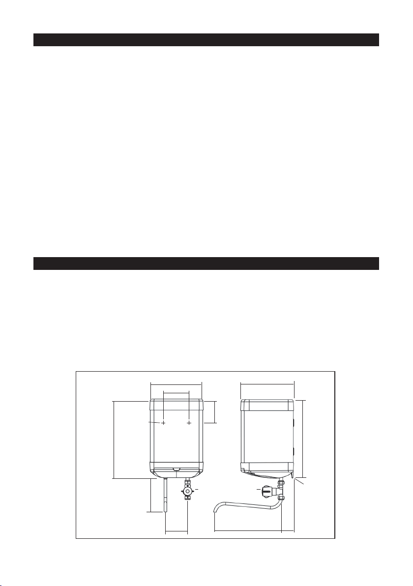
240
FIXING HOLE
240
57
105
120
356
349
140
COLD WATER INLET VALVE
2 KEYHOLE
FIXING SLOTS
6mm WIDE
300
FIGURE 01 : DIMENSIONS
100
3
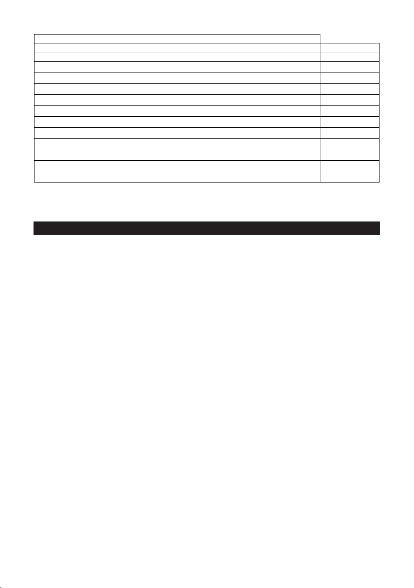
Table: Technical parameters in accordance with European Commision regulations
814/2013 and 812/2013
3.0 INSTALLATION
3.1 LOCATION
3.1.1 Inlet must always be on the right.
3.1.2 The outlet of this water heater acts as a vent and must not be blocked or
restricted in any way.
3.1.3 Only use Elson open outlet spouts.
3.1.4 The installation must be carried out in accordance with the relevant
requirements of the appropriate Building Regulations. Either The Building
Regulations, The Building Regulations (Scotland), The Building Regulations
(Northern Ireland), The Water Fittings Regulations or Water Byelaws in
Scotland.
3.1.5 Select a suitable site but check that:
a) There is enough clearance under the heater to allow removal of the element
plate (210mm).
b) When using the outlet spout, it will swing over the sink (or sinks) to be
supplied.
c) There are no hidden services where the wall is to be drilled.
3.1.6 Mark the position of the xing holes (as shown in gure 01).
3.1.7 Drill and plug the hole positions.
3.1.8 Screw in the top two screws leaving heads 3mm from the wall.
3.1.9 Hang the heater on the two top screws.
3.1.10 Screw in bottom screw to secure heater.
3.1.11 The water heater is designed to be connected directly to the mains via the
valve provided.
It is recommended that a WRAS listed isolating valve (not supplied) be tted in
the water supply pipe to the heater to allow for servicing.
3.1.12 To remove the terminal cover use a large at bladed screwdriver to relieve the
snaps located towards the front of the terminal cover at either side. Gripping
the cover at the front, pull downwards.
3.1.13 To t the cover, locate the hinge at the back. Slide the snaps into place. Apply
Direct
Supplier’s name or trade mark ELSON
Supplier’s model identifier EOS7
Storage volume V in litres 7.0
Mixed water at 40 °C V40 in litres 9
The declared load profile XXS
The water heating energy efficiency class of the model C
The water heating energy efficiency in % 31.4
The annual electricity consumption in kWh 587
Daily fuel consumption Q fuel in kWh 2.850
The thermostat temperature settings of the water heater, as placed on the market by the
supplier
60°C
Specific precautions that shall be taken when the water heater is assembled, installed or
maintained and disposed of at end of life
See Section 2 to 5

4
pressure to the front of the cover pushing it backwards and upwards until it
snaps securely in place.
3.2 PLUMBING
3.2.1 Connect the control valve supplied to the inlet pipe on the water heater.
3.2.2 Connect the cold water main to the control valve using 15mm outside diameter
pipe (either copper to BS EN 1057 or stainless steel to BS 4127).
3.2.3 Push the outlet spout directly into the outlet tting.
3.2.4 To remove outlet spout:
a) Remove terminal cover.
b) Push white ring upwards towards body of tting.
c) Pull spout downwards.
3.3 ELECTRICAL
3.3.1 Warning: This appliance must be earthed. It is suitable for a.c. supply only.
Electrical installation must be carried out by a competent electrician and be in
accordance with the latest I.E.E. regulations.
3.3.2 Nominal cross-section of supply cable must be at least 1.5mm2. A double pole
isolating switch with a contact separation of at least 3mm in each pole must be
incorporated in the supply.
3.3.3 Remove the terminal cover.
3.3.4 Strip the outer sheath and insulation on the cable to the required lengths, push
the cable through the grommet provided, this will be held by the cable grip
when the connections are made (see Figure 02).
3.3.5 Loosen the top screws securing the cable grip.
3.3.6 Pass the cable underneath the cable grip and through the top moulding.
3.3.7 Make the connections to the terminal block as follows:
Live (brown or red wire) to terminal marked “L”
Neutral (blue or black wire) to terminal marked “N”
Earth (green or green/yellow wire) to terminal marked .
3.3.8 Secure the cable in the cable grip by tightening the two screws.
3.3.9 Set the adjustable thermostat by rotating the control to the required
temperature.
It is recommended that it is set to lowest acceptable temperature to meet user
requirements. This will minimise the risk of scalding and reduce the level of
scaling in hard water areas.
3.3.10 Replace terminal cover.

5
FIGURE 03: WIRING DIAGRAM
OUTLET
INLET CABLE CLAMP
TERMINAL BLOCK
EARTH POST
ELEMENT
THERMOSTAT CONTROL
FIGURE 02: INTERNAL LAYOUT
DRAIN PLUG
THERMAL CUT-OUT
CAPILLARY STAT
TO ELEMENT
GREEN&YELLOW
BROWN/RED
BLUE/BLACK
EARTH
LIVE (RED)
NEUTRAL (BLACK)
THERMAL FUSE
THERMOSTAT
TERMINAL BLOCK
THERMOSTAT BULB
CABLE
GROMMET

6
4.0 COMMISSIONING
5.0 FAULT FINDING
DO NOT SWITCH ON HEATER UNTIL IT IS FILLED WITH WATER
4.1 Fill with water by opening tap and leaving open until a full bore of water ows
from the outlet.
4.2 Switch on water heater at double pole isolating switch. The heater will heat
water to the temperature set on the thermostat.
4.3 Check water is heating correctly.
7 litre 3kW - after 10 mins water temperature will increase by 60°C
4.4 Pass instruction leaet to user and draw their attention to the following two
statements:
DO NOT USE HEATER IF THE WATER IS THOUGHT TO BE FROZEN
Switch off immediately at the isolating switch if the water does not ow freely.
Any damage resulting from freezing will not be covered by the guarantee.
DURING HEATING THE OUTLET WILL DRIP
This is due to the expansion of water inside the heater and is normal for
heaters of this type. It does not indicate that the valve is faulty and
overtightening of the valve can result in damage.
Your EOS7 water heater should give you trouble free operation, however, should a
problem occur the table below should enable most faults to be identied with ease.
Fault nding should only be carried out by a competent person and any replacement
part should be authorised Elson spare parts.
SYMPTOM PROBABLE CAUSE ACTION
No hot water 1. Check power Check and replace as
necessary.
2. Faulty cut out
3. Faulty thermostat
4. Faulty element
Water too hot / cold 1. Thermostat set to wrong temperature Adjust thermostat.
2. Faulty thermostat Switch off, check and
replace.
No water ow 1. Frozen Switch off electrical power
and allow to thaw at room
temperature.
Do not switch on again until
full water ow restored and
full checks made for leaks
and electrical safety.
2. No mains supply Check mains.
Continuous water ow Faulty valve/tap Check and replace.

7
6.0 SPARE PARTS
7.0 GUARANTEE
8.0 ENVIRONMENTAL INFORMATION
SYMPTOM PROBABLE CAUSE ACTION
No hot water 1. Check power Check and replace as
necessary.
2. Faulty cut out
3. Faulty thermostat
4. Faulty element
Water too hot / cold 1. Thermostat set to wrong temperature Adjust thermostat.
2. Faulty thermostat Switch off, check and
replace.
No water ow 1. Frozen Switch off electrical power
and allow to thaw at room
temperature.
Do not switch on again until
full water ow restored and
full checks made for leaks
and electrical safety.
2. No mains supply Check mains.
Continuous water ow Faulty valve/tap Check and replace.
In the unlikely event of your water heater developing a fault, the following spare parts
are available:
Element plate assembly 7 litre 3kW 95 606 981
Element plate assembly gasket 95 611 021
Capillary thermostat 95 612 051
Control Valve 95 605 857
Spout (12”) 95 604 010
Over temperature cut-out 95 612 050
Top cover moulding 95 614 272
Terminal cover 95 614 273
Adaptor pusht 95 607 953
Adaptor long 95 607 954
Adaptor o-ring 95 607 955
Fixing fork 95 607 956
This product is guaranteed against faulty materials and manufacture for a period of 2
years from the date of purchase provided that:
The unit has been installed in accordance with the Installation and User Instructions and
all relevant Codes of Practice and Regulations in force at the time of installation, and
that all necessary controls and safety valves have been tted correctly.
Any valves and controls are of the Elson recommended type and specication.
The unit has not been modied or tampered with in any way and has been regularly
maintained as detailed in the Installation and User Instructions.
The unit has been used only for heating potable water.
The unit is not guaranteed against damage by frost, and the inner container with integral
immersion heater is not guaranteed against excessive scale build-up.
This guarantee in no way affects the statutory rights of the consumer.
Elson’s policy is one of continuous product development and, as such, we reserve the
right to change specications without notice.
This product is manufactured from many recyclable materials.
At the end of its useful life it should be disposed of at a Local Authority Recycling Centre
in order to realise the full environmental benets. Insulation is by means of CFC-free
polyurethane foam.
This product does not contain any substances harmful to health; it does not contain any
asbestos.

8
9.0 SPARES STOCKISTS
Electric Water Heating Co.
2 Horsecroft Place, Pinnacles,
Harlow, Essex CM19 5BT
Tel: 0845 0553811
E-mail: [email protected]
SPD - Special Products Division
Units 9 & 10 Hexagon Business Centre
Springfield Road, Hayes
Middlesex UB4 0TY
Tel : 020 8606 3567
Newey & Eyre
Unit 3 - 5 Wassage Way
Hampton Lovett Ind. Estate,
Droitwich, Worcestershire WR9 0NX
Tel : 01905 791500
Fax: 01905 791501
UK Spares Ltd.
Unit 1155 Aztec West,
Almondsbury,
Bristol BS32 4TF
Tel: 01454 620500
Alternatively, contact your local supplying merchant, wholesale branch or use our online stockist finder
at www.interpartspares.co.uk
Parts Center
Tel: 0344 292 7057
www.partscenter.co.uk
Customer Service:
Tel: 0344 8711530
Fax: 0344 8711528
E-mail: customer[email protected]
Table of contents
Other Elson Water Heater manuals


Popular Water Heater manuals by other brands

State Water Heaters
State Water Heaters 100 SERIES parts list

Eternal
Eternal GU32DV Operator's manual

Bradley
Bradley S19-788H Installation

State Water Heaters
State Water Heaters 110C Installation manual and owner's guide

eta
eta 733 user manual

Stream33
Stream33 S33HTX15 Installation, Warnings, and Operation Instructions


Rinnai
Rinnai REU-VRM1120WD-E Infinity 11e Installation and user manual

State Water Heaters
State Water Heaters SEH-250 instruction manual

Viessmann
Viessmann Vitocell 100 Service instructions

STIEBEL ELTRON
STIEBEL ELTRON SHW 200 ACEP Operation and installation manual

Ecodan
Ecodan 150 Standard Installation and servicing instructions

Webasto
Webasto Thermo Top E installation instructions