Elson Coral Aquanox Release note

1
Pack Contents
Coral Aquanox vented water heater incorporating immersion heater(s) & thermal controls•
Visual discharge indicator•
Compression nuts & olives•
Immersion heater spanner•
Installation & servicing instructions•
Guarantee card•
Blending valve insulation kit•
IMPORTANT
Please read & understand all these instructions before commencing installation.
Please leave this manual with the user for future reference.
Coral Aquanox Installation Manual
Thermal Store Direct & Indirect Water Heaters
Installation & Servicing Instructions

2
INTRODUCTION............................................................2
TECHNICAL SPECIFICATION.......................................3
INSTALLATION GENERAL............................................6
MANUAL FILL VERSION.............................................13
COMMISSIONING.......................................................14
USER INSTRUCTIONS...............................................15
MAINTENANCE...........................................................16
PERFORMANCE.........................................................18
FAULT FINDING & SERVICING..................................21
SPARES.......................................................................22
HEAT LOSS.................................................................24
ENVIRONMENTAL INFORMATION.............................24
COMMISSIONING CHECK LIST.................................26
SERVICE RECORD.....................................................27
GUARANTEE...............................................................28
TECHNICAL SUPPORT...............................................28
THE BENCHMARK SCHEME
Benchmark places responsibilities on both
manufacturers and installers. The purpose is
to ensure that customers are provided with the
correct equipment for their needs, that it is installed,
commissioned and serviced in accordance with the
manufacturer’s instructions by competent persons
and that it meets the requirements of the appropriate
Building Regulations. The Benchmark Checklist can
be used to demonstrate compliance with Building
Regulations and should be provided to the customer
for future reference.
Installers are required to carry out installation,
commissioning and servicing work in accordance with
the Benchmark Code of Practice which is available
from the Heating and Hotwater Industry Council who
manage and promote the Scheme.
Visit www.centralheating.co.uk for more information.
IMPORTANT NOTE TO USER: PLEASE REFER TO
THE USER INSTRUCTIONS SECTION ON PAGE 15
FOR IMPORTANT INFORMATION WITH RESPECT TO
THE BENCHMARK SCHEME
CONTENTS
Thank you for purchasing an Elson Thermal Store.
The thermal store is manufactured in the UK to the
highest standards and has been designed to meet all
thelatestrelevantsafetyspecications.
The Elson Coral Aquanox thermal store is an Open
Vented Hot Water only Thermal Store (HWTS).
The stored energy in a Hot Water only Thermal Store
is only used indirectly via a natural convection hot
water heat exchanger for producing instantaneous
domestic hot water. The storage vessel of an open
vented thermal store is open to atmosphere and it uses
primary water to store thermal energy.
The thermal store is a purpose designed vented water
heater. Hot water is delivered at mains water pressure.
The unit has a stainless steel vessel, which ensures
an excellent standard of corrosion resistance. The
outer casing is a combination of resilient thermoplastic
mouldings and plastic coated corrosion proofed
steel sheet. All products are insulated with CFC free
polyurethane foam to give good heat loss performance.
(see Table 5, page 24)
This appliance complies with the requirements of the
CE marking directive and is KIWA approved to show
compliance with Water Regulations.
NOTE: Prior to installation the unit should be stored
in an upright position in an area free from excessive
damp or humidity.
IMPORTANT:
THE THERMAL STORE MUST BE INSTALLED AND
COMMISSIONED BY A COMPETENT PERSON.
PLEASE READ AND UNDERSTAND THESE
INSTRUCTIONS BEFORE INSTALLING THE
THERMAL STORE. FOLLOWING INSTALLATION
AND COMMISSIONING, THE OPERATION OF THE
THERMAL STORE SHOULD BE EXPLAINED TO THE
USER AND THESE INSTRUCTIONS LEFT WITH
THEM FOR FUTURE REFERENCE.
THIS APPLIANCE IS NOT INTENDED FOR THE
USE BY PERSONS (INCLUDING CHILDREN) WITH
REDUCED PHYSICAL, SENSORY OR MENTAL
CAPABILITIES, OR LACK OF KNOWLEDGE AND
EXPERIENCE, UNLESS THEY HAVE BEEN GIVEN
SUPERVISION OR INSTRUCTION CONCERNING
THE USE OF THE APPLIANCE BY A PERSON
RESPONSIBLE FOR THEIR SAFETY.
CHILDREN MUST BE SUPERVISED TO ENSURE
THEY DO NOT PLAY WITH THE APPLIANCE.
INTRODUCTION

3
LIMITATIONS
The Thermal Store water heater should not be used
in association with any of the following:
Solid fuel boilers or any other boiler in which the•
energy input is not under effective thermostatic
control, unless additional and appropriate safety
measures are installed.
Ascending spray type bidets or any other class•
1 back syphonage risk requiring that a type A air
gap be employed.
Steam heating plants unless additional and•
appropriate safety devices are installed.
Situations where maintenance is likely to be•
neglected or safety devices tampered with.
Water supplies that have either inadequate pressure•
or where the supply may be intermittent.
In areas where the water consistently contains a•
high proportion of solids, e.g. suspended matter
that could block the blending valve, unless
adequateltrationcanbeensured.
In areas where the water supply contains chloride•
levels that exceed 200mg/l.
TECHNICAL SPECIFICATION
Table 1: Unit weights
Type Model
Reference
Nominal
Capacity
(litres)
Weight
of unit
empty
(Kg)
Weight
of unit
full
(Kg)
Indirect 120ti 120 43 170
150ti 150 53 210
175ti 175 57 239
210ti 210 67 291
Direct 120td 120 38 165
150td 150 48 205
175td 175 52 234
210td 210 63 287
OPERATIONAL SUMMARY
Total storage volume (VT) 120ltrs
150ltrs
175ltrs
210ltrs
Maximum mains pressure 0.5MPa (5 bar)
Heat Loss 120ltr 1.75kWh/24h
150ltr 2.02kWh/24h
175ltr 2.23kWh/24h
210ltr 2.49kWh/24h
Store thermostat settings 12-85°C
+4/-6°C
Overheat thermostat settings 96°C+2/-5°C
Maximum working pressure for
DHW heat exchanger 0.5MPa (5 bar)
Pressure Loss (FDHW) 0.5 bar at
12.6ltrs/min
DHW Volume 120ltrs 115ltrs
(Volume of water >40°C 150ltrs 123ltrs
75°C store temp at 175ltrs 146ltrs
12.6ltrs/min) 210ltrs 168ltrs
DHW Outlet temperature setting 55°C (TMV2
adj 35-60°C)
Maximum working pressure for
Primary heat exchanger 1.0MPa
(10 bar)
Thermal rating of Primary
heat exchanger 11kW
Pressure Loss (FPHE) 0.2 bar at
15ltrs/min
Ingress Protection IPX2
Electrical rating 3kW @
240V ac
Weight when full See Table 1

4
Fig. 1 Key Features
2
3
1
4
5
6
9
7
8
10
11
1 Primary Coil Flow Connection - 3/4”/22mm compression
2 Primary Coil Return Connection - 3/4”/22mm compression
3 Electrical Connection Housing - IPX2
4 Visual Discharge Indicator - 22 x 28mm compression
5 Feed & Expansion Header Tank
6 Feed & Expansion Header Tank Lid
7 Blending Valve Insulation Cover
8 Hot Outlet (TMV2) - 22mm compression
9 Cold Supply Inlet - 22mm compression
10 DHW Coil Drain
11 Thermal Store Cylinder Drain

5
A
450
(375 120LTR)
316
B
620
27°
47° 310
650
Ø580
620
310
650
Ø580
A
450
(375 120LTR)
C
B
360
Note:
1.ThermalstoretestedinconformancewiththeHWAPerformanceSpecicationforThermalStores
Table 2: Dimensions and performance
Type Model
Reference
Dimensions (mm) Total
Storage
Volume
(VT)
Coil Rating (kW) Hot Water
Capacity (ltrs)
(volume of water
drawn off >40°C)
Hot Water
Capacity (ltrs)
(v40°C)
A B C Hot
Water
Coil
Primary
Coil
Store
Temp
75°C
Store
Temp
85°C
Store
Temp
75°C
Store
Temp
85°C
Direct 120td 1111 516 - 120 35 11 115 144 157 202
150td 1274 626 724 150 35 11 123 154 166 215
175td 1450 801 900 175 33 11 146 190 180 264
210td 1677 1033 1127 210 33 11 168 216 213 299
Indirect 120ti 1111 516 - 120 35 11 115 144 157 202
150ti 1274 626 - 150 35 11 123 154 166 215
175ti 1450 801 - 175 33 11 146 190 180 264
210ti 1677 1033 - 210 33 11 168 216 213 299
Fig.2Dimensionsandperformance(Auto-llversionsshown)

6
WATER SUPPLY
Bear in mind that the mains water supply to the
property will be supplying both the hot and cold water
requirements simultaneously.
It is recommended that the maximum water
demand is assessed and the water supply checked
to ensure this demand can be satisfactorily met.
Note: A high mains water pressure will not always
guaranteehighowrates.
Wherever possible the mains supply pipe should be
22mm. We suggest the minimum supply requirements
should be 0.15MPa (1.5 bar) pressure and 20 litres
perminuteowrate.However,atthesevaluesoutlet
ow rates may be poor if several outlets are used
simultaneously. The higher the available pressure and
owratethebetterthesystemperformance.
HARD WATER AREAS
The building regulations L1A: New dwellings/L1B:
Existing dwellings and the requirements set out in
the Domestic Building Services Compliance Guide
specify that ‘Where the mains total water hardness
exceeds 200 parts per million, provision should be
made to treat the feed water to water heaters and the
hot water circuit of combination boilers to reduce the
accumulation of limescale.’
To maintain the performance of the Thermal Store
water heater and in order to comply with this regulation
the hardness of the mains water should be checked
bytheinstallerandifnecessarytaproprietaryscale
reducer or water softener to the cold water supply,
refer to the manufacturers instructions for installation
for guidance.
Please consult the local water authority for additional
advice on water quality if required.
INHIBITOR
The use of a corrosion inhibitor is recommended
to prolong the performance and efciency of the
Thermal Store. Checking the concentration of
corrosion inhibitor in the Thermal Store is essential,
dose appropriately according to the size of the
Thermal Store volume in accordance with the inhibitor
manufacturer’s guidelines.
Please refer to BS 7593:2006 Code of practice for
treatment of water in domestic hot water central
heating systems.
PIPE FITTINGS
The cold feed is made via 22mm copper pipe spigot.
Primary coil pipe fittings are made via 22mm
compression ttings directly to the unit.The ttings
are threaded 3/4”BSP male parallel, should threaded
pipe connections be required.
INSTALLATION GENERAL COLD FEED
A 22mm cold water supply is recommended, however,
ifa15mm(1/2”)supplyexists,whichprovidessufcient
ow,thismaybeused(althoughmoreownoisemay
be experienced).
A stopcock or servicing valve should be incorporated
into the cold water supply to enable the Thermal
Store and its associated controls to be isolated and
serviced.
OUTLET
The hot water outlet is a 22mm compression tting
located at the thermostatic mixer valve (TMV2). Hot
water distribution pipework should be 22mm pipe with
shortrunsof15mmpipetoterminalttingssuchas
sinks and basins. Pipe sizes may vary due to system
design.
The Thermal Store can be used with most types of
terminal ttings. It is advantageous in many mixer
showers to have balanced hot and cold water supplies.
In these instances a balanced pressure cold water
connection should be placed between the cold water
supply inlet and Thermal Store cold feed connection.
Aminimumdistanceof2mtrstotherstcoldwater
draw off-take must be observed (see Fig. 4, page 8).
Outlets situated higher than the thermal Store will
give outlet pressures lower than that at the heater, a
10m height difference will result in a 0.1MPa (1 bar)
pressurereductionattheoutlet.Allttings,pipework
and connections must have a rated pressure of at least
0.5MPa (5 bar) at 80°C.
DOMESTIC HOT WATER BACK EXPANSION
During a heating cycle the expansion of water in
the DHW heat exchanger must be accommodated.
Expansion back into the mains may not always be
possible. (For example, a double check valve may be
tted in the mains supply). If required the minimum
expansion vessel size recommended is 1ltr. This must
bettedupstreamoftheDHWexchangerasshownin
the schematic. (Figure 4, Page 8)
Any method or product used for accommodating the
expansion must comply with the Water Regulations
and relevant standards.
MANUAL HANDLING GUIDANCE
The appliance exceeds the recommended weight for
a one man lift. Upon installation it will be necessary
to get assistance when lifting or manoeuvring the
product into place. Use of mechanical lifting aids may
be necessary.
DO NOT LIFT THE APPLIANCE BY THE ATTACHED
PIPEWORK OR ANCILLARY COMPONENTS.

7
Fig. 3: Siting the Unit
SITING THE UNIT
TheThermalStoremustbeverticallyoormounted.
Although location is not critical, the following points
should be considered:
The Thermal Store should be sited to ensure•
minimum dead leg distances, particularly to the
point of most frequent use.
Avoid siting where extreme cold temperatures• will
be experienced. All exposed pipe work should be
insulated.
Access to associated controls and immersion•
heaters must be available to provide for the
servicing and maintenance of the system. Where
these controls are installed against a wall a minimum
distance of 300mm must be left (see Fig. 3).
For the autoll versions a minimum distance of•
225mm must be left free above the unit in order to
comply with the access requirements of the water
regulations. This requirement is for replacement
oftheballoatvalveifnecessary.
EnsurethattheoorareafortheThermalStoreis•
level and capable of permanently supporting the
weight when full of water. (see Table 1, Page 3)
Hot Outlet
Adjustable 180°
Wall
Min 300mm
maintenance
access
Min 300mm
maintenance
access
Min 225mm
Access for oat valve maintenance (Auto-ll version only)

8
Schematics
P
CWS
Direct model
The hydraulic schematics within this document are for guidance only and do not constitute system design. Some components may not be detailed for clarity purposes.
Lock Shield Valve
Strainer
Double Reg. Valve
Drain Cock
Angle pattern Drain Cock
Expansion Vessel
AAV
Flow Setter
Automatic Bypass Valve
Safety Valve
T& P Valve
2 Port Motorised Valve
Automatic Air Vent
P
S
Pressure GaugeAssembly
Tundish
Temperature Sensor
Air Separator
Combined Isolation & Check
Valve with Thermometer
Aqua
Aqua Stat
Immersion Heater
Room Stat
Programmer
Anti-Gravity Dip
Safety Discharge Vessel
Pump
Pressure Reducing Valve
Isolation Valve
Single Check Valve
Thermostatic Mixing Valve
Double Check Valve
Thermostatic Radiator Valve
Radiator Lock Shield Valve
Filling Loop
Flexible Connection
Flow Meter
Stop Cock
AGD
Key
CWS
Indirect model
AAV Gas
2 metres is required for
expansion in pipework
before nearest cold
draw-o
Where expansion down the mains is not possible install an
expansion vessel with a capacity not less than 1000ml
2 metres is required for
expansion in pipework
before nearest cold
draw-o
Where expansion down the mains is not possible install an
expansion vessel with a capacity not less than 1000ml
Fig. 4: Technical Hydraulic Schematics

9
Fig. 5: Blending Valve Insulation

10
SAFETY
DISCONNECT FROM THE MAINS ELECTRICAL
SUPPLY BEFORE REMOVING ANY COVERS.
Never attempt to replace the immersion heater(s) other
than with the recommended immersion heater(s).
DO NOT BYPASS THE THERMAL CUT-OUT(S)
IN ANY CIRCUMSTANCES. Ensure the two male
spade terminations from the combined thermostat and
thermalcut-outarepushedrmlyontotheterminations
on the element plate assembly.
(See Fig. 6)
Incaseofdifcultycontactservicesupport;contact
details available at the back of this booklet.
ELECTRICAL SUPPLY
All electrical wiring should be carried out by a
competent electrician and be in accordance with the
latest I.E.E Wiring Regulations.
Each circuit must be protected by a suitable fuse
and double pole isolating switch with a contact
separation of at least 3mm in both poles.
The immersion heater(s) should be wired in accordance
with Fig 6. The immersion heater(s) MUST be earthed.
The supply cable should be 1.5mm2 3 core exible
cable H05BN4-F to BS EN 50525-2-21:2011 and must
be routed through the cable grip provided with the
outersheathofthecablermlysecuredbytightening
the screws on the cable grip.
DO NOT operate the immersion heaters until the
cylinder has been lled with water.
Ensure the thermostat and thermal cut-out sensing
bulbs are pushed fully into the pockets on the element
plate assembly.
PLUMBING CONNECTIONS
Direct Thermal Stores require the following pipework
connections.
Cold water supply to and from inlet.•
Outlet to hot water draw off points.•
Discharge pipework from visual indicator.•
All connections are 22mm compression. However,
3/4”BSP parallel threaded ttings can be tted to the
primary coil connections if required.
INSTALLATION - DIRECT
Fig. 6: Electrical connections (direct schematic)
NL
1.5mm² 3 Core
sheathed cable
H05BN4-F

11
SAFETY
DISCONNECT FROM THE MAINS ELECTRICAL
SUPPLY BEFORE REMOVING ANY COVERS.
Never attempt to replace the immersion heater(s) other
than with the recommended authorised immersion
heater(s).
DO NOT BYPASS THE THERMAL CUT-OUT IN
ANY CIRCUMSTANCES. Ensure the two male
spade terminations from the combined thermostat
and thermal cut-out are pushed firmly onto the
corresponding terminations on the element plate
assembly. (See Fig. 7)
Incase ofdifculty contactservice support;contact
details available at the back of this booklet.
ELECTRICAL SUPPLY
All electrical wiring should be carried out by a
competent electrician and be in accordance with the
latest I.E.E Wiring Regulations.
Each circuit must be protected by a suitable fuse
and double pole isolating switch with a contact
separation of at least 3mm in both poles.
The immersion heater should be wired in accordance
with Fig 7. The immersion heater MUST be earthed.
The supply cable should be 1.5mm2 3 core exible
cable H05BN4-F to BS EN 50525-2-21:2011 and must
be routed through the cable grip provided with the
outersheathofthecablermlysecuredbytightening
the screws on the cable grip.
DO NOT operate the immersion heaters until the
cylinder has been lled with water.
Ensure the thermostat and thermal cut-out sensing bulbs
are pushed fully into the pockets on the element plate
assembly.
PLUMBING CONNECTIONS
Indirect Thermal Stores require the following
pipework connections.
Cold water supply to and from inlet.•
Outlet to hot water draw off points.•
Discharge pipework from visual indicator.•
Connection to the primary circuit.•
All connections are 22mm compression. However,
3/4”BSPparallelthreadedttingscanbettedtothe
primary coil connections if required.
BOILER SELECTION
The boiler should have a control thermostat and non
self-resetting thermal cut-out and be compatible with
thermal storage water heaters.
Where use of a boiler without a thermal cut-out is
unavoidable a “low head” open vented primary circuit
should be used. The feed and expansion cistern head
above the Thermal Store should not exceed 2.5m.
PRIMARY CIRCUIT CONTROL
AmotorisedvalveMUSTbettedontheprimaryow
to the cylinder heat exchanger and wired in series with
the indirect control thermostat and thermal cut-out
ttedtotheunit.
Primary circulation to the Thermal Store heat
exchangermustbepumped;gravitycirculationWILL
NOT WORK.
SPACE AND HEATING SYSTEMS CONTROLS
Controls will be required ensure the safe operation
of the unit within the central heating system. Other
controls will be necessary to control the space heating
requirements and times that the system is required to
function, see Fig. 9 below.
The Thermal store is compatible with most heating
controls, examples of electrical circuits are shown
in Figs. 8 and 9 (Page 12). However, other systems
may be suitable, refer to the controls manufacturers’
instructions, supplied with the controls selected, for
alternative system wiring schemes.
INSTALLATION - INDIRECT
LN
1 2 3
Element Connections
1.5mm² 3 Core
sheathed cable
H05BN4-F
Indirect control
wiring
Fig. 7: Electrical connections (indirect schematic)

12
Fig. 8: Schematic wiring diagram - Basic 2 x 2 port valve system
Fig. 9: Schematic wiring diagram - 3 port mid position valve system. N.B. Must be used in conjunction with 2 port
zone valve supplied

13
MANUAL FILL
Thestoreisprovidedwithaexibletemporarylling
loop which MUST be disconnected after installation
to comply with the requirements of the Water Supply
(Water Fittings) Regulations 1999.
The feed & expansion header tank water level should be
checkedregularly.Ifrequiredllwithcleancoldwater
viathellinglooptotheappropriatelevelasshown
onthesightglass.Donotoverllthetank.Ensurethat
the header tank lid is securely replaced, this reduces
the amount of water lost through evaporation during
operation.
If the level in the feed and expansion tank should
dropbetweenservices,theexiblellingloopshould
be attached and the valve opened to let water slowly
intotheheadertank.Thisshouldbelledtotheline
indicated on the side of the units header section. The
llingloopshouldthenbedisconnected.
In the event of leak the only water that can be lost is
the water held within the Thermal Store at that time.
MANUAL FILL VERSION
Fig.10:ManualllVersion
Fill level of header tank with internal indicator
Upper Limit
Lower Limit
Filling loop
Fig.11:AutollWaterLevel
Fig.12:ManualllWaterLevel

14
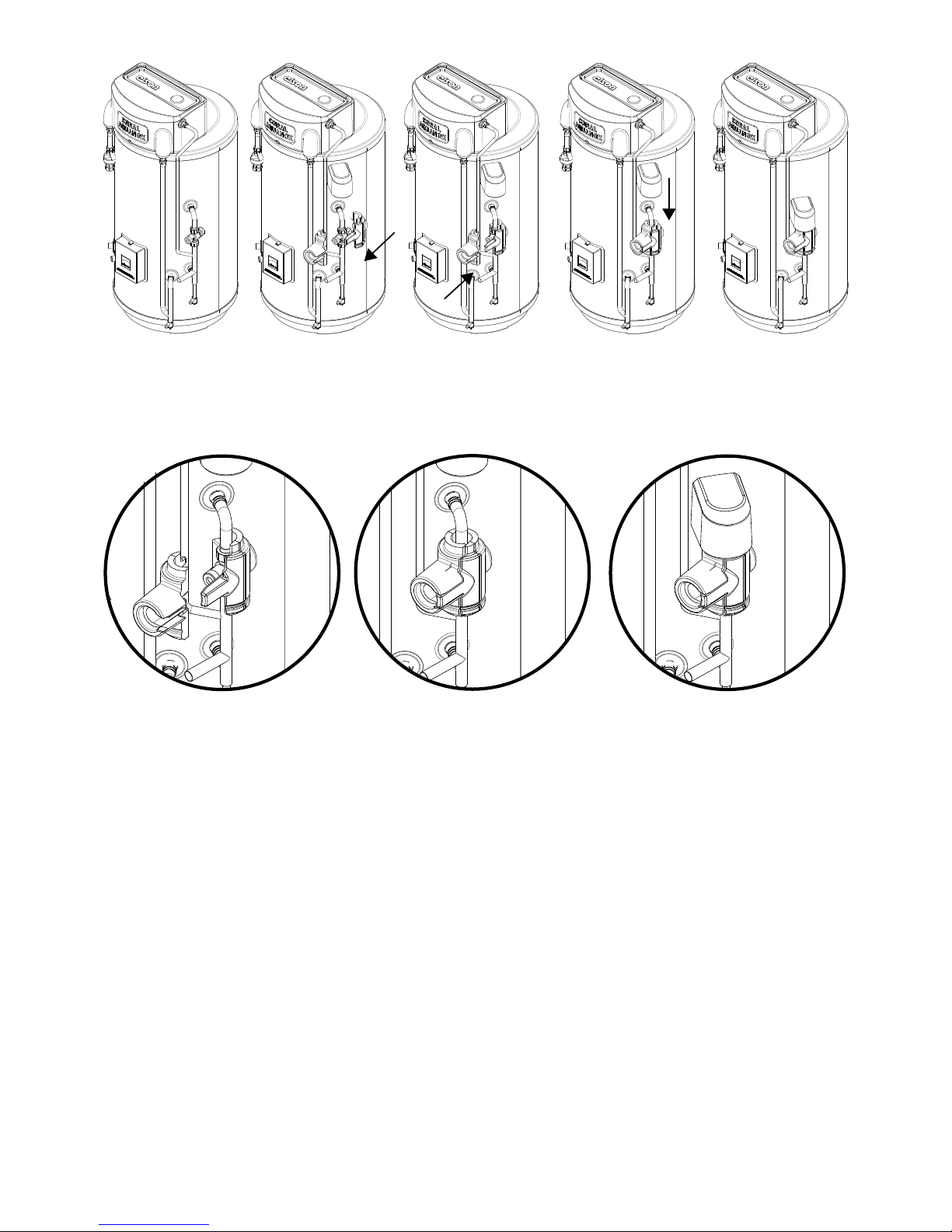
FILLING THE UNIT WITH WATER
Ensurethatallttingsandimmersionheatersarecorrectly
ttedandtightened.Animmersionheaterkeyisprovided
to aid tightening the immersion heater(s)
AUTO FILL UNIT
Check all connections for tightness including the•
immersion heater(s). An immersion heater key
spanner is supplied for this purpose.
Ensure that both drain cocks are CLOSED.•
Open a hot tap furthest from the Thermal Store.•
Openthe mains stop cockto ll theunit.When•
water ows from the tap, allow to run for a few
minutestothoroughlyushthroughanyresidue,
dirt or swarf, then close the tap.
Open successive hot taps to purge the system•
of air.
TheThermalStorewillcontinuetollviatheball•
valve located in the feed & expansion header tank.
This will stop when the cylinder store is full.
Set the level of water in the cistern by adjusting•
theheightoftheballoatusingtheinternalwater
height gauge as shown in Fig.11 page 13.
MANUAL FILL UNIT
Check all connections for tightness including the•
immersion heater(s). An immersion heater key
spanner is supplied for this purpose.
Ensure that both drain cocks are CLOSED.•
Open a hot tap furthest from the Thermal Store.•
Openthe mains stop cockto ll theunit.When•
water ows from the tap, allow to run for a few
minutestothoroughlyushthroughanyresidue,
dirt or swarf, then close the tap.
Open successive hot taps to purge the system•
of air.
The ‘lling loop’ is used for introducing mains•
water into the cylinder for lling and topping up
purposes.The‘lingloop’hasanisolatingvalve
at each end. To introduce water into the system,
undo one of these valves completely and gently
opentheothervalvetocontroltherateofowof
water into the cylinder. Introduce water until the
sight gauge on the feed & expansion tank is level
withthebottomlllineasshowninFig.12page
13.Turnbothvalvesofffully.Thetemporarylling
loop should be disconnected after installation to
comply with the requirements of the Water Supply
(Water Fittings) Regulations 1999
The feed & expansion header tank water level•
should be checked regularly. If required ll with
cleancoldwaterviathellingloopto‘topup’.
SYSTEM CHECKS
Upon commissioning a competent engineer should:
Check all water connections for leaks and rectify•
as necessary.
Check water pressure – maximum 5.0bar•
Check operation of all service valves•
COMMISSIONING Check operation of the blending valve and test that•
the water temperature (hot ow mix) is at 55°C
when the store temperature is operating at 75°C.
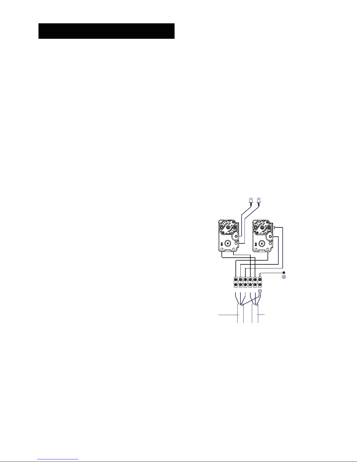
Check operation of the immersion heater•
thermostats and settings.
Complete the service record at the back of the
commissioning booklet provided to comply with
the manufacturers guarantee and Benchmark
requirements.
DIRECT UNIT
Switch on electrical supply to the immersion heater(s)
and allow the cylinder to heat up to normal working
temperature (75°C recommended, approximately
graduation 4 on the thermostat). If necessary the
temperature can be adjusted by inserting a flat
bladed screwdriver in the adjustment knob on top of
the immersion heater thermostat and rotating. The
adjustment range 1 to 5 represents a temperature
range of 37°C to 85°C. Check the operation of
thermostat(s).
INDIRECT UNIT
Fill the indirect (primary) circuit following the boiler
manufacturer’s commissioning instructions. To ensure
thecylinderprimaryheatexchangerislled,the2port
motorised valve should be manually opened by moving
the lever on the motor housing to the MANUAL setting.
When the primary circuit is full return the lever to the
AUTOMATIC position.
Switch on the boiler, ensure the programmer is set to
Domestic Hot Water and allow the cylinder to heat up
to a normal working temperature (75°C recommended,
approximately graduation 5 on the thermostat).
If necessary the temperature can be adjusted by
insertingaatbladedscrewdriverintheadjustment
knob and rotating. The minimum thermostat setting
is 12°C.
The adjustment range 1 to 5 represents a temperature
range of 37°C to 85°C.
Check the operation of the indirect thermostat and
motorised valve during the heating cycle.
BENCHMARK LOG BOOK
On completion of the installation and commissioning
procedures detailed in this manual the Benchmark
“Installation, Commissioning and Service Record Log,
pages 26 and 27 should be completed and signed off
by the competent installer or commissioning engineer
in the relevant sections. The various system features,
location of system controls, user instructions and
what to do in the event of a system failure should be
explained to the customer. The customer should then
countersign the BenchmarkTM commissioning checklist
(page 26) to accept completion. The Service Record
should be lled in when any subsequent service or
maintenance operation is carried out on the product.

15
WARNINGS
IF STEAM DISCHARGES FROM THE OVERFLOW
VISUAL INDICATOR SHUT DOWN THE BOILER
OR IMMERSION HEATER(S). DO NOT TURN OFF
ANY WATER SUPPLY. CONTACT A COMPETENT
INSTALLER FOR WATER HEATERS TO CHECK THE
SYSTEM.
IF A FAULT IS SUSPECTED CONTACTA COMPETENT
INSTALLER.
FLOW PERFORMANCE
When initially opening hot outlets a small surge in
ow may be noticed as pressures stabilise. This is
quite normal with hot water systems. In some areas
cloudiness may be noticed in the hot water. This is
due to aeration of the water, is quite normal and will
quickly clear.
TEMPERATURE CONTROLS – DIRECT UNIT
IMMERSION HEATER(S)
A combined adjustable thermostat and thermal cut-out
is provided for each immersion heater. The thermostat
is factory set to give a water storage temperature of
approx. 75°C. Access to the thermostat can be made
by opening the immersion heater cover - DISCONNECT
THE ELECTRICAL SUPPLY BEFORE OPENING
THE COVER(S). Temperature adjustment is made
by inserting a at bladed screwdriver in the slot on
the adjustment spindle on top of the thermostat and
rotating. The adjustment range 1 to 5 represents
a temperature range of 37°C to 85°C (75°C will be
approximately position 4). If in any doubt contact a
competent electrician.
DO NOT bypass the thermal cut-out(s) in any
circumstances.
TEMPERATURE CONTROLS - INDIRECT UNIT
TheThermalStoreunitsarettedwithanindirectcontrol
thermostat and thermal cut-out. These controls must be
wired in series with the motorised zone valve to interrupt
theowofprimarywateraroundtheheatexchangercoil
when the control temperature has been reached. The
controls are located within the terminal housing along
with the immersion heater thermostat. The thermostat
is factory set to give a water storage temperature of
approx. 75°C. Access to the thermostat can be made
by opening the terminal housing cover - DISCONNECT
THE ELECTRICAL SUPPLY BEFORE OPENING THE
COVER. Temperature adjustment is made by inserting
aatbladedscrewdriverintheadjustmentspindleand
rotating. The minimum thermostat setting is 12°C. The
adjustment range 1 to 5 represents a temperature range
of 37°C to 85°C (75°C will be approximately position 4).
If in any doubt contact a competent electrician.
An immersion heater is also provided for use should
the indirect heat source be shut down for any reason. The
immersion heater control temperature is set using the
immersion heater thermostat.
DO NOT bypass the thermal cut-out(s) in any
circumstances.
OPERATIONAL FAULTS
Operational faults and their possible causes are
detailed in the Fault Finding section of this book. It
is recommended that faults should be checked by a
competent installer.
ELECTRIC TARIFFS
Direct units are designed to use predominantly low
tariff electricity but with a boost switch during normal
tariff periods. The thermal store is designed to heat
water to 75°C. At this temperature performance is
maintained with minimal heat loss, keeping running
costs to a minimum.
BOOST ELEMENT
During periods of prolonged hot water draw-off or
during cold weather conditions the use of the ‘boost’
element may be more common. If the inlet cold water
temperature is very low more energy will be required
to heat the store.
The boost element will ensure hot water delivery when
the indirect heat store is not available for any reason.
HOLIDAY
It is safe to turn off the power to the Thermal Store and
shut off the water supply if you go on holiday.
THE BENCHMARK SCHEME
Elsy & Gibbons is a licensed member of the Benchmark
Scheme which aims to improve the standards of
installation and commissioning of domestic heating
and hot water systems in the UK and to encourage
regular servicing to optimise safety, efciency and
performance.
Benchmark is managed and promoted by the Heating
and Hotwater Industry Council. For more information
visit www.centralheating.co.uk.
Please ensure that the installer has fully completed the
Benchmark Checklist (Page 26) of this manual and that
you have signed it to say that you have received a full
and clear explanation of its operation. The installer is
legally required to complete a commissioning checklist
as a means of complying with the appropriate Building
Regulations (England & Wales).
AllinstallationsmustbenotiedtoLocalArea
Building Control either directly or through a
Competent Persons Scheme. A Building Regulations
ComplianceCerticatewillthenbeissuedtothe
customer who should, on receipt, write the
NoticationNumberontheBenchmarkChecklist.
This product should be serviced regularly to optimise
its safety, efciency and performance.The service
engineer should complete the relevant Service Record
on the Benchmark Checklist after each service.
The Benchmark Checklist may be required in the event
of any warranty work.
USER INSTRUCTIONS

16
MAINTENANCE REQUIREMENTS
Thermal store hot water systems have a continuing
maintenance requirement in order to ensure safe
working and optimum performance.
The maintenance checks described below should be
performed by a competent person on a regular basis,
e.g. annually to coincide with boiler maintenance.
After any maintenance, please complete the relevant
Service Interval Record section of the Benchmark
Checklist on Page 27 of this document.
INSPECTION
The immersion heater boss can be used as an access
for inspecting the cylinder internally. Ensure the unit is
drained before removal of immersion heater.
DE-SCALING THE DHW EXCHANGER
The hot water heat exchanger may be de-scaled in the
eldbyaqualiedtechnicianusingahighpressure
de-scaling pump and suitable acidic de-scaling
chemical (e.g. Fernox DS3). The store must be cooled
to between 30 and 40°C before commencing the de-
scaling. This must be carried out by a skilled person
because of the specialist equipment needed.
DE-SCALING IMMERSION HEATER(S)
Before removing the immersion heater(s) the unit
must be drained. Ensure the water, electrical supply and
boiler are OFF before draining. Attach a hosepipe to
thedraincockhavingsufcientlengthtotakewaterto
a suitable discharge point below the level of the unit.
Open a hot tap close to the unit and open the drain
cock to drain the unit.
DIRECT UNITS
Switch on electrical supply to the immersion heater(s)
and allow to heat up to normal working temperature
(75°C recommended, approximately graduation 4 on
the thermostat). If necessary the temperature can
beadjustedbyinsertingaatbladedscrewdriverin
the adjustment knob on top of the immersion heater
thermostat and rotating. The adjustment range 1 to 5
represents a temperature range of 12°C to 68°C. Check
the operation of thermostat(s) and that no water has
issued from the expansion relief valve or temperature/
pressure relief valve during the heating cycle.
INDIRECT UNITS
Open the cover(s) to the immersion heater housing(s)
and disconnect wiring from immersion heater(s)
thermostat(s). Remove thermostat by carefully pulling
outwards. Remove thermostat capillary sensors from
the pockets on the immersion heater. Unscrew
immersion heater backnut(s) and remove immersion
heater from the unit. A key spanner is supplied with
the cylinder unit for easy removal/tightening of the
immersion heater(s). Over time the immersion heater
gasket may become stuck to the mating surface. To
breakthesealinsertaatbladedscrewdriverintoone
of the pockets on the immersion heater and gently
lever up and down.
Carefully remove any scale from the surface of the
element(s). DO NOT use a sharp implement as
damage to the element surface could be caused.
Ensure sealing surfaces are clean and seals are
undamaged,ifindoubttanewgasket
(part number 95 611 822).
Replace immersion heater(s) ensuring the lower
(right angled) element hangs vertically downwards
towards the base of the unit. It may be helpful to
support the immersion heater using a round bladed
screwdriver inserted into one of the thermostat pockets
whilst the backnut is tightened. Replace thermostat
capillaries into pocket. Replace the immersion heater
thermostat by carefully plugging the two male spade
terminations on the underside of the thermostat head
into the corresponding terminations on the element.
Rewire, check, close and secure immersion heater
housing cover(s).
RE-COMMISSIONING
Check all electrical and plumbing connections are
secure. Close the drain cock. With a hot tap open, turn
onthecoldwatersupplyandallowunittorell.DONOT
switch on the immersion heater(s) or boiler until the
unitisfull.Whenwaterowsfromthehottapallowit
toowforashortwhiletopurgeairandushthrough
any disturbed particles. Close the hot tap and then
open successive hot taps in the system to purge any
air. When completely full and purged check the system
for leaks. The heating source (immersion heater(s) or
boiler) can then be switched on.
INHIBITOR
The use of a corrosion inhibitor is required to maintain
the performance and cylinder guarantee of the
Thermal Store. Checking the concentration of the
corrosion inhibitor in the Thermal Store is essential
to prevent corrosion. Dose appropriately according to
the size of the volume in accordance with the inhibitor
manufacturer’s guidelines.
Please refer to BS 7593:2006 Code of practice for
treatment of water in domestic hot water central
heating systems.
MAINTENANCE

17
Step 1: Drain feed & expansion tank
(note: drain tank only)
Step 2: Release feed & expansion
tank pipe connections
Step 3: Remove feed & expansion tank
xing bolt & slide forwards to remove
Fig. 13: Header Tank Removal
Step 1: Drain feed & expansion tank
(note: drain tank only)
Step 2: Release connection pipe, remove
rear tank by unhooking and lifting
Fig. 13a: 210litre Header Tank Removal

18
PERFORMANCE
DHW Performance of a thermal store
Coral Aquanox 120ltr
0
10
20
30
40
50
60
Draw-off volume (l)
DHW outlet temperature (°C)
75°C
85°C
0 20 40 60 80 100 120 140 160 180 200
DHW Performance of a thermal store
Coral Aquanox 150ltr
0
10
20
30
40
50
60
Draw-off volume (l)
DHW outlet temperature (°C)
75°C
85°C
0 20 40 60 80 100 120 140 160 180 200
Fig. 14: 120ltr Hot Water Performance
Fig. 15: 150ltr Hot Water Performance

19
DHW Performance of a thermal store
Coral Aquanox 175ltr
0
10
20
30
40
50
60
Draw-off volume (l)
DHW outlet temperature (°C)
75°C
85°C
0 20 40 60 80 100 120 140 160 180 200 220 240
DHW Performance of a thermal store
Coral Aquanox 210ltr
0
10
20
30
40
50
60
Draw-off volume (l)
DHW outlet temperature (°C)
75°C
85°C
0 20 40 60 80 100 120 140 160 180 200 220 240 260 280
Fig. 16: 175ltr Hot Water Performance
Fig. 17: 210ltr Hot Water Performance

20
Pressure Loss Characteristics of DHW heat exchanger
Coral Aquanox
0.00
0.10
0.20
0.30
0.40
0.50
0.60
0.70
0.80
0.90
0 6.3 9.45 12.6 (FDHW) 13.86 15.75
DHW flow rate (l/min)
Pressure Loss (bar)
Pressure Loss Characteristics of a Primary heat exchanger
Coral Aquanox
0.00
0.05
0.10
0.15
0.20
0.25
0.30
0.35
0.40
0 7.5 11.25 15 (FPHE) 16.5 18.75
Primary flow rate (l/min)
Pressure Loss (bar)
Fig. 18: Pressure Loss Characteristics: DHW Exchanger
Fig. 19: Pressure Loss Characteristics: Primary Heat Exchanger
Table of contents
Other Elson Water Heater manuals
Popular Water Heater manuals by other brands

STIEBEL ELTRON
STIEBEL ELTRON DCE 3-1 Trend Operation and installation

Solahart
Solahart SOLAR WATER HEATERS owner's manual

Bradford White
Bradford White S-SW2-60R6DS Service manual

Chaffoteaux & Maury
Chaffoteaux & Maury Bayard 10 CFPV manual

Ferroli
Ferroli Talent Installation and use instructions

Webasto
Webasto Thermo Top E installation instructions