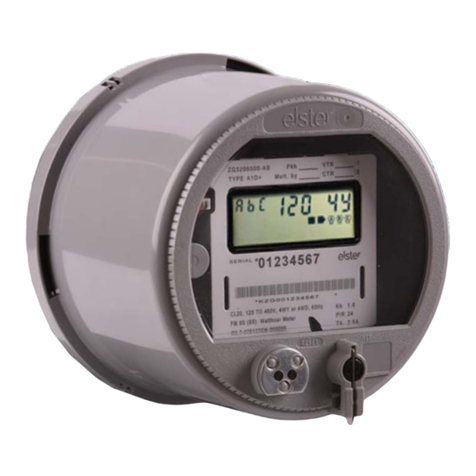
Elster A100C Installation and operation manual

33333333333
A100C
BS Electronic Single Phase Meter
Operating & Maintenance
Instructions
Meter Variants
All variants are available with IrDA or IEC 62056-21
communications
•Import kWh - one rate
•Import kWh - two rate
•Import kWh, Power flow insensitive - one rate
•Import kWh, Power flow insensitive - two rate
•Import and export kWh - one rate
•Import and export kWh - two rate
M130 300 2C
5.2007


A100C Single Phase Meter
Operating & Maintenance Instructions
M130 300 2C
5.2007
Other Products in this Series
A100C DIN Electronic single phase meter M130 300 1
A102C BS Electronic Single Phase Meter M130 400 1
with kvarh measurement capability
A102C DIN Electronic Single Phase Meter M130 400 2
with kvarh measurement capability
A120 BS Electronic Single Phase Meter with M130 004 1
Load Profiling
A120 DIN Electronic Single Phase Meter with M130 003 1
Load Profiling


A100C - BS Single Phase Electronic Meter 1
______________________________________________________________________________
CONTENTS
1FOREWORD .......................................................................................................................3
2WARNING ...........................................................................................................................4
3COMPLIANCE WITH STANDARDS AND EUROPEAN DIRECTIVES .............................4
4APPROVALS ......................................................................................................................5
5GENERAL DESCRIPTION .................................................................................................5
5.1 Features...............................................................................................................................5
5.2 Options ................................................................................................................................6
6GENERAL DESCRIPTION .................................................................................................6
6.1 Basic Meter Types...............................................................................................................6
6.2 Current Ratings....................................................................................................................6
6.3 Connections.........................................................................................................................7
6.4 Meter Accuracy....................................................................................................................7
6.5 Meter Case..........................................................................................................................7
7TIME OF USE REGISTERS................................................................................................8
7.1 Rate Change Lockout..........................................................................................................8
8OVERVOLTAGE OPERATION...........................................................................................8
9POWER FLOW INSENSITIVE MODE................................................................................8
10 TEST INDICATOR...............................................................................................................9
11 SECURITY FEATURES......................................................................................................9
11.1 Data Retention.....................................................................................................................9
11.2 Recordable Security Features.............................................................................................9
11.2.1 Reverse Energy...................................................................................................................9
Reverse Run Count.............................................................................................................9
Reverse Energy Event Flag...............................................................................................10
Reverse Energy Reading ..................................................................................................10
11.2.2 Power Fail Counter............................................................................................................10
11.2.3 Time - Rate 1 and Rate 2 ..................................................................................................10
11.2.4 Cumulative Time in Anti-creep ..........................................................................................10
11.2.5 Watchdog Reset Counter..................................................................................................10
11.3 Power Flow Insensitive Mode............................................................................................10
12 DISPLAY ...........................................................................................................................11
12.1 Introduction........................................................................................................................11
12.2 Display Modes (all meter types)........................................................................................12
12.3 All Meter Types..................................................................................................................12
12.4 Import Only One/Two Rate Meter Displays.......................................................................14
12.5 Import/Export.....................................................................................................................15
13 COMMUNICATIONS.........................................................................................................17
13.1 IrDA Meter Communications .............................................................................................17
13.1.1 IrDA Meter Optional Serial Data Output............................................................................17
13.2 IEC 62056 - 21 Meter Communications............................................................................18
13.3 Data Available....................................................................................................................18
14 PULSING OUTPUT...........................................................................................................19
14.1 Output Configurations........................................................................................................19
14.2 Output Characteristics.......................................................................................................19
15 TECHNICAL DATA...........................................................................................................20
©Elster Metering Limited - M130 300 2C - 5.2007
2A100C - BS Single Phase Electronic Meter
_____________________________________________________________________________
16 INSTALLATION ................................................................................................................21
16.1 Unpacking..........................................................................................................................21
16.2 Handling.............................................................................................................................21
16.3 Storage ..............................................................................................................................21
16.4 Installation Site ..................................................................................................................21
16.5 Fixing and Connection.......................................................................................................22
17 COMMISSIONING.............................................................................................................23
18 MAINTENANCE................................................................................................................23
19 DISPOSAL AND RECYCLING.........................................................................................23
FIGURES
Figure 1 - Model Code ..................................................................................................................24
Figure 1A - Model Code (Continued) ..............................................................................................25
Figure 2 - A100C Meter ................................................................................................................26
Figure 3 - Typical A100C Nameplates..........................................................................................27
Figure 4 - Load Curves .................................................................................................................28
Figure 5 - Terminal Arrangements................................................................................................29
Figure 6 - Dimensions and Fixing Centres ...................................................................................30
Figure 7 - Typical Single Rate, Import Meter Display...................................................................31
Figure 7A - Typical 2 Rate Import/Export Meter Display.................................................................32
Figure 7B - Displayable Data ..........................................................................................................33
Figure 8 - Password Access Levels (IEC 62065-21 Meters.........................................................33
APPENDIX A ........................................................................................................................................
A1 IrDA Data Serial Output................................................................................................35
A2 IrDA Serial Word Formats ............................................................................................38
APPENDIX B - CHECKING KWH REGISTRATION ACCURACY
B1 Introduction...................................................................................................................39
B2 Checking Meter Accuracy Using the Test LED............................................................39
B2.1 Comparing a number of LED pulses with a substandard meter register advance ......39
B2.2 Comparing LED pulses with substandard meter pulses..............................................40
B3 Checking Meter Registration Accuracy from Register Advances ................................40
B3.1 Using the 'Test' values on the meter display................................................................40
B3.2 Using the register readings from the IrDA output.........................................................41
B3.2.1 Comparing the IrDA register reading advance with that of a substandard meter........41
B3.2.2 Comparing IrDA register advances with values calculated by the IrDA receiving PC.41
APPENDIX C - IRDA DATA SOFTWARE
C1 Introduction...................................................................................................................42
C1.1 Running the Software...................................................................................................42
©Elster Metering Limited - M130 300 2C - 5.2007
Operating & Maintenance Instructions 3
_____________________________________________________________________________________
1 FOREWORD
HEALTH AND SAFETY
Compliance with Instructions in this Manual
The instructions and information in this manual are provided in compliance with Section 6
of the UK Health and Safety at Work Act, as amended by Schedule 3 of the Consumer
Protection Act 1987.
The purchaser is responsible for making sure that everyone, whether in his employment
or not, who will be associated with the products supplied by Elster Metering Systems, and
to which these instructions and information apply, are made familiar with the contents of
this manual.
This applies to all persons who may be involved in activities such as unpacking,
inspecting, testing, setting, cleaning, installing, commissioning, operating, maintaining,
decommissioning or disposing of the products.
Safety of Persons using Electrical Products
Employers have a duty to ensure, as far as is reasonably practicable, the Health, Safety
and Welfare at Work of all their employees. Employers must therefore ensure that
employees are informed, trained and supervised and use proper working procedures to
ensure the safety of themselves and others.
The information provided in this manual is intended to ensure that products are properly
installed and otherwise handled in order to maintain them in a safe condition.
In the UK, employers have duties under the Health and Safety at Work Act 1974 and the
various regulations stemming therefrom.
In countries outside the UK, employers should ensure proper compliance with the Health
and Safety Legislation that is applicable to them.
Putting into Service
Products supplied by Elster Metering Systems have been designed and manufactured,
in accordance with appropriate standards, to operate under specified conditions, when
properly installed.
The purchaser or delegated contractor is responsible for the "Putting into Service" of any
Elster Metering Systems products that have been supplied as "Non-connected". All
related activities must therefore be carried out with due regard to any applicable
legislation, standards and good practice.

4A100C - BS Single Phase Electronic Meter
_____________________________________________________________________________
2 WARNING
Internal Electronic Circuits
The internal electronic circuits of these meters are, due to technical necessity, connected
to MAINS LIVE.
Removal of Terminal Cover
All supplies connected to the meter should be isolated before any attempt is made to
remove the meter terminal cover. Failure to do so may result in electric shock or death.
Live parts will be exposed when the terminal cover or main cover is removed.
The main cover is permanently fixed. It cannot be removed without destroying the meter.
Liquid Crystal Display
Liquid crystals are toxic. If a display is damaged, avoid contact with the liquid. If the liquid
makes contact with the skin it must be washed off immediately with water.
Seek medical advice.
3 COMPLIANCE WITH STANDARDS AND EUROPEAN
DIRECTIVES
Meters are marked with the European CE mark, in accordance with the Marking Directive
93/68/EEC, to indicate compliance with the requirements of the EMC Directive
89/336/EEC.
Safety requirements for meters are addressed in specific metering standards outlined
below. The CE Mark does not denote compliance with the European Low Voltage
Directive 73/23/EEC, which specifically excludes electricity meters.
The A100C meter measures active energy according to the requirements of EN 62053-
21:2003 for indoor kWh meters of protective Class II and accuracy Class 1 or 2.
The degree of protection is to IP53, IEC 60529:1989.
The meter complies with BS7856:1996 - dimensional requirements.
Devices for metering and billing electrical energy described in this manual are supplied
for use in a ‘Fixed Installation’ only. Devices described are a ‘component of a system
only’ and therefore outside the scope of European Directives 2002/95/EC RoHS
(Restriction of the Use of Certain Hazardous Substances in Electrical Equipment) and
2002/96/EC WEEE (Waste Electrical and Electronic Equipment).
©Elster Metering Limited - M130 300 2C - 5.2007
Operating & Maintenance Instructions 5
_____________________________________________________________________________________
4 APPROVALS
Variables of the A100C are approved by the Office of Gas and Electricity Markets
(OFGEM) in compliance with European and British metering legislation (Approval
Number 984). These are identified in the model code. Other variants will be approved by
International Authorities in line with local requirements
5 GENERAL DESCRIPTION
The A100C is a single phase meter for domestic applications of up to 100A.
The meter offers Class 1 or 2 accuracy, the option of IrDA or IEC 62056 - 21 (formerly
IEC 1107) communications and security data as standard.
The following versions of the A100C are available:
Import kWh – one or two rates
Import kWh – one or two rates, Power flow insensitive (See Section 9)
Import and export kWh – one or two rates
A high contrast, large character Liquid Crystal Display that uses chevrons to indicate the
active element can support any language by appropriate legends on the nameplate.
The meter stores comprehensive security data that can be included in the display
sequence.
The A100C has the option of IrDA or IEC 62056 -21 communications.
The IrDA variant is read only and reads the meter data electronically using a PC or
handheld device. As an option the meter auxiliary terminals can be configured at
manufacture to transmit the same absolute data as the IrDA port or to transmit a pulsed
output.
The IEC 62056 - 21 variant of the meter offers bi-directional communications allowing
reading of all stored data and the programming of ‘personality’ data. Access to the
various items is controlled by a multi-level password system. As a manufacturing option,
a pulsed output is available via the meters auxiliary terminals.
5.1 Features
•Accuracy Class 1 or Class 2
•kWh import or kWh import and export
•20 years certification life
•Large digit (9.8mm) multilingual display with chevron information identification
•Extensive security data
•12kV impulse withstand
•High security, compact design (97mm High x 130mm Wide x 47mm Deep)
•BS double insulated, glass filled polycarbonate case
•Permanently fixed main cover
•IP53 in accordance with IEC 60529:1989

6A100C - BS Single Phase Electronic Meter
_____________________________________________________________________________
5.2 Options
•One or two rates controlled by an external device
•IrDA or IEC 62056 – 21 communications
•Power flow insensitive mode (import plus export)
•Auxiliary terminals configured for:
- SO output (IEC 62053-31)
- Serial data output (IrDA communications only)
•Standard or extended terminal cover
6 GENERAL DESCRIPTION
6.1 Basic Meter Types
SJ… BS Case
6.2 Current Ratings
The A100C can be supplied for use with 120V or 230V single phase two wire systems at 50
or 60Hz. The following current ratings and pulses/kWh are available:
OFGEM Approved
A100C Current Voltage Frequency
SJ1LA..
SJ1MA..
SJ1NA..
20 - 100A
10 - 100A
5 - 100A
220 - 250V
220 - 250V
220 - 250V
50Hz
50Hz
50Hz
Other Variants
SJ1LA..
SJ1MA..
SJ1NA..
SJ1LC..
SJ1MC..
SJ1NC..
20 - 100A
10 - 100A
5 - 100A
20 - 100A
10 - 100A
5 - 100A
220 - 250V
220 - 250V
220 - 250V
110 - 127V
110 - 127V
110 - 127V
60Hz
60Hz
60Hz
50 or 60Hz
50 or 60Hz
50 or 60Hz
Other current ratings are available. Contact Elster Metering Systems.
See Figure 1 for full model code details.
©Elster Metering Limited - M130 300 2C - 5.2007

Operating & Maintenance Instructions 7
_____________________________________________________________________________________
6.3 Connections
Meters are designed for direct connection to 50 Hz or 60 Hz supplies. They may be marked
for use at reference voltages in the range 220 - 250V or 110 - 127V, and are rated to a
maximum current 100A Imax.
Terminal Arrangements
Main terminals 8.2mm diameter bores, M6 cross/slot head combination screws
Auxiliary terminals 3.2mm diameter bore, M3 cross/slot head combination screws
Meter nameplates (see Figure 3) are marked with the rated current, reference voltage,
frequency and relevant meter constant (for example pulses/kWh).
Connection diagrams are shown inside the terminal cover.
6.4 Meter Accuracy
The A100C measures active energy in accordance with the requirements of IEC 62053-
21:2003 for indoor kWh meters of protective Class II and accuracy Class 1 or Class 2.
Typical accuracy curves are shown in Figure 4.
The design of the meter ensures life long stability. No adjustments are required in the field.
6.5 Meter Case
The terminal arrangements are shown in Figure 5.
The main meter cover is fixed permanently to the base at manufacture.
The case is double insulated to protective Class II. The case provides an ingress protection
rating of IP53 in accordance with IEC 60529:1989.
The base, with its integral terminal block is moulded in glass-filled polycarbonate.
The terminal cover (standard or extended) is moulded in light beige coloured polycarbonate.
The main cover is moulded in tinted, clear polycarbonate.
Figure 6 illustrates the outline fixing dimensions.

8A100C - BS Single Phase Electronic Meter
_____________________________________________________________________________
7 TIME OF USE REGISTERS
One or two rate meters are available. The rate select for a two rate meter is controlled by
an external timeswitch.
The contacts operate as follows:
a) External switch contacts open - rate select terminal open circuit
b) External switch contacts closed - rate select terminal connected to neutral
According to customer requirements specified prior to manufacture, the effect of these two
conditions is as follows:
Option 1 Option 2
a) Energy stored in Rate 1 register a) Energy stored in Rate 2 register
b) Energy stored in Rate 2 register or b) Energy stored in Rate 1 register
7.1 Rate Change Lockout
Following a successful rate change, further rate changes are held off for a 10 minute
period.
To aid testing the meter, this mechanism is inhibited for either 1 minute or 1 hour
(configured at manufacture) after power up to allow any external rate select devices to be
tested.
8 OVERVOLTAGE OPERATION
The meter has been designed to withstand a voltage of √3 x Uref (i.e. 400V for 230V
meters, 208V for 120V meters) for an indefinite period. When tested over a 12 hour
duration, the application of 400V on a 230V meter caused permanent registration error
changes of less than 0.4%.
9 POWER FLOW INSENSITIVE MODE
Power Flow Insensitive Mode is a security feature that allows an import only meter to
increment its main kWh registers regardless of whether the meter is importing or exporting
energy.
When this option is enabled, the pulsing LED indicates identically for both import and
export. The Reverse Energy Event Flag, Reverse Energy Counts and Reverse kWh
Register respond only to reverse (export) power flow and continue to function as in normal
operation. Power flow Insensitive Mode is enabled at time of manufacture.
©Elster Metering Limited - M130 300 2C - 5.2007
Operating & Maintenance Instructions 9
_____________________________________________________________________________________
10 TEST INDICATOR
A red test output LED is provided which pulses in accordance to the following configurations:
Import only meter: The LED pulses for forward energy only
Import meter with Power Flow Insensitive enabled: The LED pulses for forward and reverse
energy
Import/export meter: The LED pulses for forward and reverse energy
The LED is permanently illuminated when in anti-creep (i.e. below starting current) for all
configurations.
The test indicator pulses are 40ms wide. The pulse value is 1000 p/kWh for all meter ratings
and is marked on the meter nameplate.
The LED is not modulated.
11 SECURITY FEATURES
The following security features are available.
11.1 Data Retention
All data is retained for the nominal life of the meter and is stored in non volatile memory.
Registration data for the currently active rate is saved approximately every 2 hours; when a
rate changes to become inactive; when a power fail is detected.
Security data is saved approximately every 2 hours or if a power fail is detected.
11.2 Recordable Security Features
Recordable security features are listed below. They can be read as follows:
IrDA communications port and optional serial data port (IrDA meter)
IEC 62056 - 21 port (IEC 1107 meter)
Security features are optional in the display sequence.
11.2.1 Reverse Energy
Reverse Run Count
The meter detects and stores:
The number of reverse energy events to a maximum of 255. The register will then roll over
to 1
Reverse energy event Flag
An event is detected if, in a single occurrence, an amount of reverse energy exceeding a
preset threshold (Configurable at manufacture between 1Wh and 250Wh, [default 5Wh]) is
measured. Two rate meters store a single count of reverse running events.

10 A100C - BS Single Phase Electronic Meter
_____________________________________________________________________________
Reverse Energy Event Flag
The Reverse Energy Event Flag is set when an event occurs as defined in Reverse Run
Count.
This can be inhibited at manufacture if required. Once detected, this flag will remain set
until the power to the meter is removed, then restored.
Reverse Energy Reading
Irrespective of whether the meter is set to import only or power flow insensitive mode,
reverse kWh power flow can be independently recorded and displayed.
11.2.2 Power Fail Counter
A count of the cumulative number of power downs is stored to a maximum of 65535.
The register will then roll over to 1.
11.2.3 Time - Rate 1 and Rate 2
Each complete hour the meter is active in Rate 1 and Rate 2 is recorded in separate
registers.
A count of 999999 is recordable. The register will then roll over to 1.
11.2.4 Cumulative Time in Anti-creep
This feature detects and stores each full hour the meter is in kWh anti-creep mode.
This detects abnormal consumer load patterns.
11.2.5 Watchdog Reset Counter
The Watchdog Reset Counter stores a count of the occasions when the CPU is restarted
due to abnormal operation. The maximum count is 255.
11.3 Power Flow Insensitive Mode
For import meters the meter can be configured (at time of manufacture) so that the kWh
registers (Cumulative, Rate 1, Rate 2) increment for both import and export energy
consumption. The pulsing LED indicates identically for both import and export.
The reverse energy event flag, reverse energy event counts and indicators operate in the
same manner in power flow insensitive mode.
©Elster Metering Limited - M130 300 2C - 5.2007
Operating & Maintenance Instructions 11
_____________________________________________________________________________________
12 DISPLAY
12.1 Introduction
The A100C meter is fitted with a high contrast, wide viewing angle liquid crystal display
with seven large digits (9.8mm x 3.5mm). The smaller digit (reference indicator) may
identify the parameters being displayed. Seven chevrons identify displayed information.
This identification is marked on the nameplate.
Typical display sequences and a list of displayable data are shown in Figures 7.
Reference Indicator
Alarm
Reverse Run
Count Active
kWh Reverse Hours
At power up the segment test pattern is shown. This will remain displayed for a period set
at manufacture (6, 8, 10, 12 or 15 seconds) called the dwell time.
The display will then sequence through the programmed displays.
Dwell time – 6, 8, 10, 12 or 15 seconds
Next display
Note: the values displayed are frozen whilst shown on the display - even if the source
register increments. If only one display is shown, the register will be updated at the dwell
time.
The nameplate may be printed in any language, to suit customer requirements.
This is a manufacturing process that cannot be changed in the field. See Figure 3 for typical
nameplate details.
Reverse Run Indicator
The Reverse Run Indicator will be set if, in a single occurrence, an amount of reverse
energy exceeding a programmed threshold value is measured.
This value is normally set to 5Wh.
The indicator can be cleared by removing, then restoring the meter power.
As an option the display of this indicator may be hidden from the customer during the
manufacturing configuration process.

12 A100C - BS Single Phase Electronic Meter
_____________________________________________________________________________
12.2 Display Modes (all meter types)
The resolution of the display can be set at manufacture to 7, 6 or 5 digits.
The decimal point indicator can be configured to be a point or a comma and set to 0, 1 or 2
places.
Seven digit resolution to one Six digit resolution to one
decimal place. Point separator decimal place. Comma
separator
7 Digits 6 Digits 5 Digits
1 2 3 4 5 6 7
2 3 4 5 6 7. 8
3 4 5 6 7. 8 9
2 3 4 5 6 7
3 4 5 6 7. 8
4 5 6 7. 8 9
3 4 5 6 7
4 5 6 7. 8
5 6 7. 8 9
Internal storage is :- 1 2 3 4 5 6 7. 8 9 0
For 6 digit registration the display is display is a window of this.
e.g. 1 2 3 4 5 6 7. 8 9 0
12.3 All Meter Types
The following items may be included in the display sequence.
Segment Test Pattern
The Test Pattern is always displayed at power up. All segments should be 'on'.
The Test Pattern is optional in the display sequence.
Power Up Display Sequence
Note: The two chevrons to the left vertical of the display are included in the Test Pattern only
at power up.
©Elster Metering Limited - M130 300 2C - 5.2007
Operating & Maintenance Instructions 13
_____________________________________________________________________________________
Count
Reverse run/Power fail
The Reverse Run Count display is shown below (for export meters the display shows the
number of instances the meter has been exporting).
Chevrons Reference id
4 - Count 1 - Reverse Run (Max 255)
2 - Power Fail (Max 65535)
Hours
The following durations can be displayed:
Time in Rate 1
Time in Rate 2
Total energised time
Cumulative kWh anti-creep time
The format of the display is shown as the number hours (hhhhhh). The total on time of 6852
hours for Rate 2 is shown below.
Chevrons Reference id
5 - Hours 1 - Time in Rate 1
2 - Time in Rate 2
3 - Total on Time
4 - Cum kWh Anti-creep Hours
Error Codes
Errors are shown in the following format.
Er 00001
Er 00010
Er 00100
Hardware Error
Configuration Checksum Error
Billing Data Checksum Error
The example shows 'Configuration Checksum Error'. If no errors exist, this display is skipped.
The following manufacturing options are available:
1. Omit the error display from the display sequence if an error occurs
2. Display or omit the alarm indicator from the display if an error occurs

14 A100C - BS Single Phase Electronic Meter
_____________________________________________________________________________
Alarm Indicator
The alarm indicator can be displayed if a meter error is displayed or omitted from the display
if errors are not displayed. Errors that will cause the alarm to be set are - Hardware error,
configuration checksum error or billing checksum error.
12.4 Import Only, One/Two Rate Meter Displays
The chevrons on the meter display have the following meaning:
Reverse Hours
Import kWh Count Active
(Chevrons with no identification are not used)
Dial Test
Dial test can be displayed as a manufacturing option for the first one hour or two hours after
power up. It is prefixed with ‘tSt’ and includes 2 decimal digits. Chevron 1 indicates that
import kWhs is being displayed. Chevron 3 indicates that reverse energy is displayed
(Optional).
For 2 Rate meters the display values are the sum of the Rate 1 and Rate 2 register values.
Chevrons Reference id
1 - kWh
3 - Reverse energy
No used
Single Rate kWh - normal operation
Chevron 1 indicates kWh is displayed. Chevron 3 indicates that reverse energy is being
displayed (optional).
Chevrons Reference id
1 - kWh
3 - Reverse energy
Not used
©Elster Metering Limited - M130 300 2C - 5.2007
Operating & Maintenance Instructions 15
_____________________________________________________________________________________
2 Rate kWh – normal operation
Chevron 1 indicates kWh for Rate 1, Rate 2 or cumulative is displayed.
The 'reference id' identifies the rate being displayed. Chevron 3 indicates that reverse energy
is being displayed (optional). Chevron 7 indicates when the rate displayed is currently active.
Chevrons Reference id
1 - kWh
3 - Reverse energy
7 - Active rate
1 = Rate 1
2 = Rate 2
C = cumulative (Rate 1 + Rate 2)
12.5 Import/Export
Export kWh Hours
Import kWh Count Active
(Chevrons with no identification are not used)
Dial Test (Import/Export Meter)
Dial test can be displayed as a manufacturing option for the first one hour or two hours after
power up. It is prefixed with ‘tSt’ and includes 2 decimal digits. Chevron 1 indicates import
kWhs being displayed. Chevron 3 indicates that export kWhs is being displayed (optional).
For 2 Rate meters the display values are the sum of the Rate 1 and Rate 2 register values.
Chevrons Reference id
1 - kWh (import)
3 - kWh (export) Not used

16 A100C - BS Single Phase Electronic Meter
_____________________________________________________________________________
Single Rate kWh Import/Export Meter – normal operation
Chevron 1 indicates Import kWh is displayed. Chevron 3 indicates that export kWhs is being
displayed.
Chevrons Reference id
1 - kWh (import)
3 - kWh (export) Not used
2 Rate kWh Import/Export Meter – normal operation
Chevron 1 indicates Import kWh for Rate 1, Rate 2 or cumulative is displayed. The 'reference
id' identifies the rate being displayed. Chevron 3 indicates that export kWhs is displayed.
Chevron 7 indicates that rate being displayed is currently active.
Chevrons Reference id
1 - kWh (import)
3 - kWh (export)
7 - Active Rate
1 = Rate 1
2 = Rate 2
C = Cumulative (Rate 1 + Rate 2)
©Elster Metering Limited - M130 300 2C - 5.2007
Table of contents
Other Elster Measuring Instrument manuals

Elster
Elster EnCal 3000 Quad User manual

Elster
Elster F90S User manual

Elster
Elster BK-G1.6 User manual

Elster
Elster T-Probe User manual

Elster
Elster A1140 User manual

Elster
Elster 2 Series Guide

Elster
Elster A3 ALPHA User manual

Elster
Elster F90S User manual

Elster
Elster BK-G1.6 User manual

Elster
Elster ALPHA User manual

Elster
Elster TRZ2 User manual

Elster
Elster BK-G Series User manual

Elster
Elster EA_Gatekeeper User manual

Elster
Elster themis plus Operating instructions

Elster
Elster TC210 Specification sheet

Elster
Elster A3 ALPHA User manual

Elster
Elster A1100 Installation and operation manual

Elster
Elster enCore FC1 User manual

Elster
Elster A3 ALPHA User manual

Elster
Elster gas-lab Q1 Guide