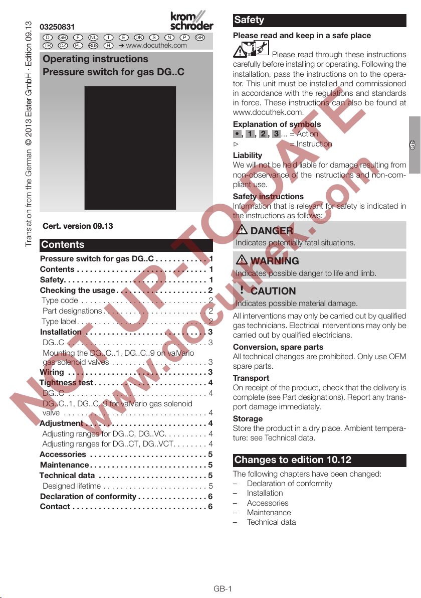
Elster krom schroder DG C Series User manual

DK S N P GR
➔www.docuthek.com
D GB F NL I E
TR CZ PL RUS H
© 2013 Elster GmbH · Edition 09.13
Cert. version 09.13
Please read and keep in a safe place
Please read through these instructions
carefully before installing or operating. Following the
installation, pass the instructions on to the opera-
tor. This unit must be installed and commissioned
in accordance with the regulations and standards
in force. These instructions can also be found at
www.docuthek.com.
Explanation of symbols
• , 1 , , 3 ... = Action
▷= Instruction
Liability
We will not be held liable for damage resulting from
non-observance of the instructions and non-com-
pliant use.
Safety instructions
Information that is relevant for safety is indicated in
the instructions as follows:
DANGER
Indicates potentially fatal situations.
WARNING
Indicates possible danger to life and limb.
CAUTION
Indicates possible material damage.
All interventions may only be carried out by qualified
gas technicians. Electrical interventions may only be
carried out by qualified electricians.
Conversion, spare parts
All technical changes are prohibited. Only use OEM
spare parts.
Transport
On receipt of the product, check that the delivery is
complete (see Part designations). Report any trans-
port damage immediately.
Storage
Store the product in a dry place. Ambient tempera-
ture: see Technical data.
Changes to edition 10.1
The following chapters have been changed:
– Declaration of conformity
– Installation
– Accessories
– Maintenance
– Technical data
Operating instructions
D
GB
F
NL
I
E
GB-1
Cert. version 09.13
© 2013 Elster GmbH · Edition 09.13Translation from the German
0350831 Safety
Contents
Pressure switch for gas DG..C
Pressure switch for gas DG..C ............1
Contents ..............................1
Safety.................................1
Checking the usage .....................
Type code .............................2
Part designations ........................2
Type label..............................2
Installation ............................3
DG..C ................................3
Mounting the DG..C..1, DG..C..9 on valVario
gas solenoid valves ......................3
Wiring ................................3
Tightness test ..........................4
DG..C ................................4
DG..C..1, DG..C..9 for valVario gas solenoid
valve .................................4
Adjustment ............................4
Adjusting ranges for DG..C, DG..VC..........4
Adjusting ranges for DG..CT, DG..VCT........4
Accessories ...........................5
Maintenance ...........................5
Technical data .........................5
Designed lifetime ........................5
Declaration of conformity ................6
Contact ...............................6

GB-2
D
GB
F
NL
I
E
Checking the usage
DG..C
For monitoring increasing or decreasing positive
pressure of natural gas, town gas, LPG, flue gas,
biologically produced methane and air.
This function is only guaranteed when used within the
specified limits, see page 5 (Technical data).
Any other use is considered as non-compliant.
Type code
Code Description
DG Pressure switch for gas
15 – 500 Max. setting in mbar
/15 – /500 Max. 2nd setting in mbar
VSwitching point adjustable on hand wheel
CCompact design
TT-product
1
3
4
5
6
8
9
Connection for valVario controls
Connection at the side for CG 15 – 30
2 x Rp 1/4 internal thread, pressure test point
Rp 1/4 internal thread
R 1/8 external thread
R 1/4 external thread
Optional connection for valVario controls
DSealant (for external thread only)
-5
-6
4-pin plug, without socket
4-pin plug, with socket
S
W
NO contact
Change-over contact
GWith gold-plated contacts
Part designations
DG..C..1, DG..C..9 for valVario controls
2
3
2
1
1
1
1
2
3
3
2
5
4
1Socket with seal
2 x O-rings
32 x retaining screws
4Gas inlet for DG..C..1
5Gas inlet for DG..C..9 (option)
DG..C..3 for CG 15 – 30
2
3
2
1
1
1
1
2
3
3
2
5
4
1Socket with seal
1 x O-ring
32 x retaining screws
DG..C..4, DG..C..5 with internal thread
2
3
2
1
1
1
1
2
3
3
2
5
4
1Socket with seal
2 x Rp 1/4 internal thread for DG..C..4,
1 x Rp 1/4 internal thread for DG..C..5
3Pressure test point for DG..C..4
DG..C..6, DG..C..8 with external thread
2
3
2
1
1
1
1
2
3
3
2
5
4
1Socket with seal
R 1/8 external thread for DG..C..6,
R 1/4 external thread for DG..C..8
Type label
Installation position, max. inlet pressure, ambient tem-
perature, enclosure, voltage, current: see type label.
D-49018 Osnabrück, Germany
DG..C pmax
T IP
U
I

GB-3
D
GB
F
NL
I
E
Installation
CAUTION
Please observe the following to ensure that the DG..C
is not damaged during installation and operation:
– Continuous operation at high temperatures
(e.g. maximum ambient temperature) or gases
containing more than 0.1 %-by-vol. H2S ac-
celerate the ageing of elastomer materials and
reduce the service life.
– Use approved sealing material only.
– Check max. ambient temperature, see
page5 (Technical data).
– Max. inlet pressure p
u max.
600 mbar (8.5psig).
– Max. test pressure for testing the entire system:
temporarily <15min. 2bar (29psig).
– Protect the DG..C against dirt and moisture in
the medium to be measured, e.g. install a filter
and ensure there is a riser.
– Avoid subjecting the DG..C to strong or violent
vibrations.
– In case of highly fluctuating pressures, install a
restrictor orifice, see page 5 (Accessories).
DG..C
▷Installation in the vertical or horizontal position.
If installed in a horizontal position, the pre-
set switching point will change by 0.2mbar
(0.08"WC).
-0.2 mbar
(-0.08 "WC)
+0.2 mbar
(+0.08 "WC)
±0 mbar
(±0 "WC)
=
=
=
▷
If the DG..C is installed with the plug pointing
downwards, the enclosure is reduced to IP40.
▷
The DG..C must not be in contact with masonry.
Minimum clearance 20mm (0.79inches).
▷Ensure that there is sufficient installation space.
▷
For DG..VC, ensure unobstructed view of the
hand wheel.
1 Disconnect the system from the electrical power
supply.
Shut off the gas supply.
3 Purge the pipe.
54
Mounting the DG..C..1, DG..C..9 on valVario
gas solenoid valves
54
▷
For pressure test points for inlet pressure p
u
,
interspace pressure p
z
or outlet pressure p
d
,
select the installation position for the pressure
switch from the operating instructions of the gas
solenoid valve.
▷Use enclosed screws only.
76
Wiring
CAUTION
Please observe the following to ensure that the
DG..C is not damaged during operation:
– If the DG..C..G (DG..VCT..G) has switched a
voltage > 24V (>30V) and a current > 0.1A
at cosφ=1 or >0.05A at cosφ = 0.6 once,
the gold plating on the contacts will have been
burnt through. It can then only be operated at
this power rating or higher power rating.
– Note the switching capacity, see page 5
(Technical data).
▷
The DG..C can be connected electrically using a
tab receptacle (4.8×0.8mm) or using a socket.
▷
The DG..CT is connected electrically via a socket
with ½"NPT thread and pre-wired connection
leads.
DG..C DG..C DG..CT
▷
The DG..C is available as an NO contact or a
change-over contact.
▷
Observe contact position for decreasing/increas-
ing pressure control:
Change-over contact switches from NO2 to
NC1 for decreasing pressure control, from
NC1 to NO2 for increasing pressure control.
NO contact opens for decreasing pressure
control, contact closes for increasing pressure
control.

GB-4
D
GB
F
NL
I
E
NO
2
NC
1
COM
3
L1
NO
2
COM
3
L1
0
▷
Pressure switch DG can be used in Zone 1 and 2
hazardous areas if an isolating amplifier is instal-
led upstream in the safe area as “Ex-i” equipment
pursuant to EN60079-11 (VDE 0170-7):2007.
▷
DG as “simple electrical equipment” pursu-
ant to EN 60079-11:2007 corresponds to the
Temperature class T6, Group II. The internal in-
ductance/capacitance is Lo = 0.2 μH/Co = 8 pF.
1 Disconnect the system from the electrical power
supply.
▷Pre-wired connection leads for DG..CT:
1= blue, = red, 3= black, 4= yellow/green.
3 42
5
NO
2NC
1
COM
3
L1
2
1
3
NO
2
COM
3
L1
2
3
▷Plug insert can be rotated in 90° steps.
7 86
Tightness test
DG..C
21
N
2
<_1,5 x p
u max
DG..C..1, DG..C..9 for valVario gas solenoid
valve
1 Shut off the downstream gas pipeline close to
the valve.
Open the valve and the gas supply.
43
N
2
<_1,5 x p
u max
Adjustment
Adjusting ranges for DG..C, DG..VC
Type
Adjusting
range*
[mbar]
Switching
hysteresis**
[mbar]
DG 15..C 3 – 15 0.7 – 2
DG 17..VC 2 – 17 0.7 – 2
DG 30..VC 8 – 30 1 – 2
DG 35..C 5 – 35 1 – 2.5
DG 40..VC 5 – 40 1 – 2.5
DG 45..VC 10 – 45 1 – 2.5
DG 60..VC 10 – 60 1 – 3
DG 110..C 30 – 110 2 – 8
DG 110..VC 30 – 110 2 – 8
DG 150..VC 40 – 150 2 – 8
DG 250..C 70 – 250 5 – 15
DG 300..VC 100 – 300 6 – 20
DG 360..C 100 – 360 6 – 20
DG 500..VC 150 – 500 20 – 50
* The scale value is set to the switch-off point
(adjusting tolerance = ±15% of the scale value).
▷
Deviation from the switching point during testing
pursuant to EN1854 Gas pressure switches:
±15%.
Adjusting ranges for DG..CT, DG..VCT
Type
Adjusting
range*
["WC]
Switching
hysteresis**
["WC]
DG 15..CT 1.2 – 6.0 0.28 – 0.8
DG 17..VCT 0.8 – 6.8 0.28 – 0.8
DG 30..VCT 3.2 – 12.0 0.4 – 0.8
DG 35..CT 2 – 14 0.4 – 1.0
DG 40..VCT 2 – 16 0.4 – 1.0
DG 45..VCT 4 – 18 0.4 – 1.0
DG 60..VCT 4 – 24 0.4 – 1.2
DG 110..CT 12 – 44 0.8 – 3.2
DG 110..VCT 12 – 44 0.8 – 3.2
DG 150..VCT 16 – 60 0.8 – 3.2
DG 250..CT 28 – 100 2.0 – 6.0
DG 300..VCT 40 – 120 2.4 – 8.0
DG 360..CT 40 – 144 2.4 – 8.0
* The scale value is set to the switch-on point
(adjusting tolerance = ±15% of the scale value).
** Mean switching differential at min. and max. set-
ting

GB-5
D
GB
F
NL
I
E
▷
For the DG..VC, the switching point is adjustable
via hand wheel.
2 31
4 5
Accessories
See Technical Information DG (D, GB, F) –
www.docuthek.com
Maintenance
We recommend a function check once a year, or
every six months if operated with biologically pro-
duced methane.
Technical data
Gas type: natural gas, town gas, LPG (gaseous), flue
gas, biologically produced methane (max. 0.1%-by-
vol. H2S) and air.
Max. inlet pressure pu max.600mbar (8.5psig).
Max. test pressure for testing the entire system:
temporarily <15min. 2bar (29psig).
Switching capacity:
DG..C, 24 – 250 V AC:
I = 0.05 – 5 A at cosϕ=1,
I = 0.05 – 1A at cosϕ= 0.6.
DG..C..G, 5 – 250VAC:
I = 0.01 – 5A at cosϕ=1,
I = 0.01 – 1A at cosϕ= 0.6.
DG..C..G, 5 – 48 VDC: I = 0.01– 1 A.
DG..VCT, 30 – 240 VAC:
I = 5A at cosϕ= 1,
I = 0.5A at cosϕ= 0.6.
DG..VCT..G, <30VAC:
I = 0.1A at cosϕ= 1,
I = 0.05A at cosϕ= 0.6.
RoHS compliant pursuant to 2002/95/EC.
Ambient temperature:
DG..C: -10 to +70°C (14 to 158°F),
DG..CT: -15 to +60°C (5 to 140°F).
Diaphragm pressure switch, silicone-free.
Diaphragm: NBR.
Housing: glass fibre reinforced PBT plastic with
low gas release.
Lower housing section: AlSi12.
Enclosure:
IP54 pursuant to DIN EN 60529 with standard
socket pursuant to DINEN175301-803,
IP00 with AMP plug.
Safety class: 1.
Weight: 60g (2.12 oz).
Designed lifetime
The Pressure Equipment Directive (PED) and the
Energy Performance of Buildings Directive (EPBD)
demand regular checks on and maintenance of heat-
ing systems in order to ensure a high level of use
in the long term, a clean method of operation and
safe function.
The service life on which the construction is based,
hereinafter referred to simply as the “designed
lifetime”, is compiled from the relevant standards.
You can find further explanations in the applicable
rules and regulations and on the afecor website
(www.afecor.org).
This information on the designed lifetime is based on
using the product in accordance with these operat-
ing instructions.
The product must be serviced at regular intervals.
Once the specified designed lifetime has been
reached, the safety-related functions must be
checked in accordance with the section entitled
“Maintenance”.
If the product passes the aforementioned function
tests, you can continue to use it until the next sched-
uled maintenance operation. At this point, these tests
must be repeated.
If the product fails one of the aforementioned tests,
it must be replaced immediately.
This procedure applies to heating systems. For ther-
moprocessing equipment, observe national regula-
tions.
Designed lifetime (based on date of manufacture)
in accordance with EN 1854 for pressure switches:
Medium Designed lifetime
Switching cycles Time [years]
Gas 50,000 10
Air 250,000 10
Long-term use in the upper ambient temperature
range accelerates the ageing of the elastomer ma-
terials and reduces the service life (please contact
manufacturer).

Elster GmbH
Postfach 28 09, D-49018 Osnabrück
Strotheweg 1, D-49504 Lotte (Büren)
T +49 541 1214-0
F +49 541 1214-370
GB-6
D
GB
F
NL
I
E
If you have any technical questions, please contact
your local branch office/agent. The addresses are
available on the Internet or from ElsterGmbH.
We reserve the right to make technical modifications
in the interests of progress. info@kromschroeder.com, www.kromschroeder.com
Contact
Declaration of conformity
We, the manufacturer, hereby declare that the
product DG..C, marked with product ID No.
CE-0085AQ0753, complies with the requirements
of the listed Directives and Standards.
Directives:
– 2009/142/EC
– 2006/95/EC
Standards:
– EN 13611
– EN 1854
The relevant product corresponds to the type tested
by the notified body 0085.
The production is subject to the surveillance proce-
dure pursuant to annex II, paragraph 3 of Directive
2009/142/EC and to the Quality System pursuant
to DIN EN ISO 9001:2008.
Elster GmbH
Scan of the Declaration of conformity (D, GB) – see
www.docuthek.com
SIL, PL
The pressure switches are suitable for single-chan-
nel systems (HFT = 0) up to SIL 2/PL d, and up to
SIL3/PL e when two redundant pressure switches
are installed in a double-channel architecture (HFT =
1), provided that the complete system complies with
the requirements of EN 61508/ISO 13849. The safety
function value which is actually achieved is derived
by taking all components into account (sensor – logic
– actuator). For this, the demand rate and structural
measures to avoid/detect nonconformity are to be
observed (e.g. redundance, diversity, monitoring).
Characteristic values for SIL/PL: HFT = 0
(1device), HFT = 1 ( devices), SFF > 90, DC=0,
typeA/category B, 1, , 3, 4, high demand mode,
CCF >65, ß≥.
PFHD= λD= x nop
=
1
MTTFd
0.1
B10d
U I B10d value
24 V DC 10 mA 6,689,477
230 V AC 4 mA
24 V DC 70 mA 4,414,062
230 V AC 20 mA
230 V AC 2 A 974,800
FM approved
Factory Mutual Research Class: 3510 Flow and pres-
sure safety switches.
Designed for applications pursuant to NFPA 85 and
NFPA 86.
UL listed
UL 353 Limit control.
Underwriters Laboratories
DG..CT with socket: UL listed,
DG..CT without socket: UR recognized.
AGA approved
AGA
Australian Gas Association
Approval for Russia
Certified by Gosstandart pursuant to GOST-R.
Approved by Rostekhnadzor (RTN).
RoHS compliant
Conforme a RoHS
This manual suits for next models
30
Table of contents
Popular Switch manuals by other brands

Broadcast Tools
Broadcast Tools SS 2.1 MLR/RJ Installation and operation manual

IFM
IFM Efector 150 operating instructions

Elko
Elko SOU-2 manual

Compaq
Compaq StorageWorks SAN Switch Integrated/32 Installation and hardware guide

Audio Authority
Audio Authority Ascentic MH10-HD user manual

IBM
IBM RackSwitch G8000 Guide