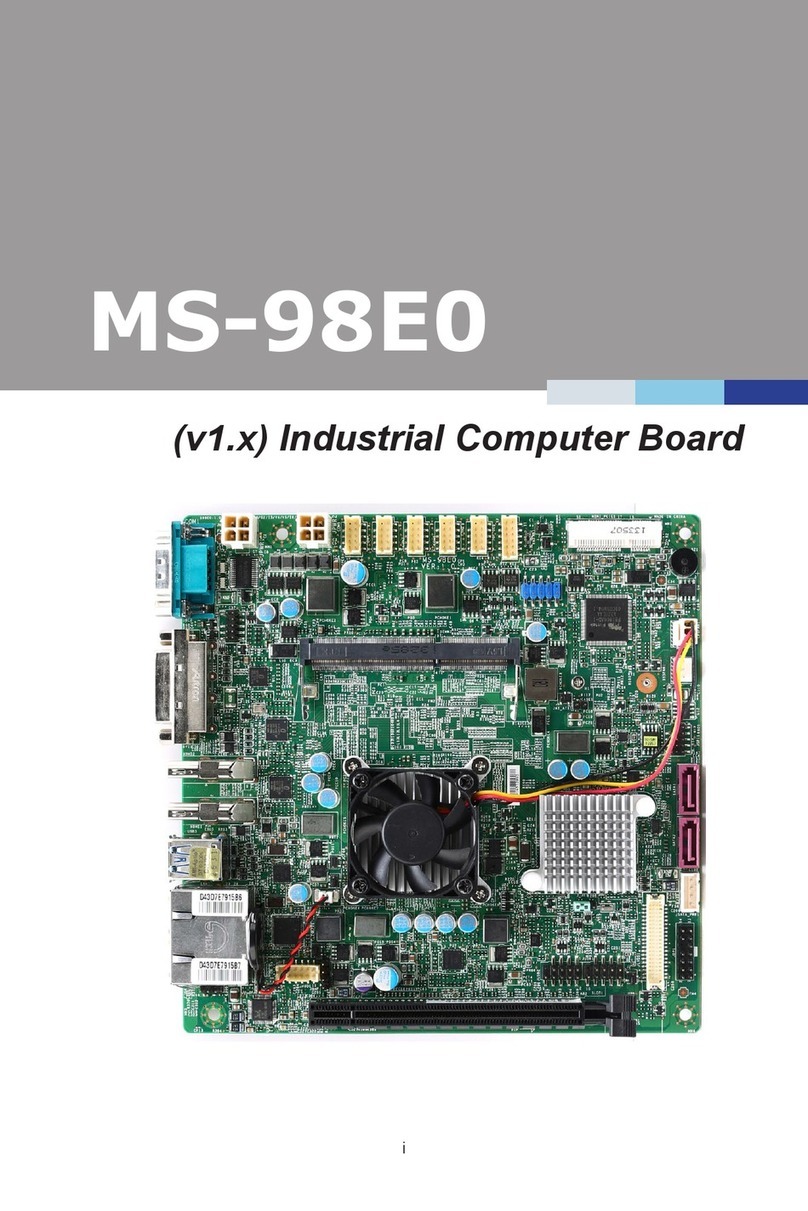
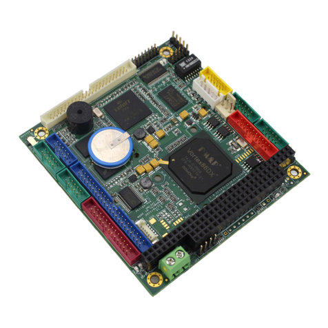
ELTEC EUROCOM 238 User manual

EUROCOM®238
Hardware Manual
Revision 1A

Revision History
Revision Changes Date
1A First Edition,
valid for Hardware revision 1A,
03.07.00, ac
WARNING ! This equipment generates and can radiate radio frequencies.
If not installed in accordance with the instruction manual, it may cause
interference to radio communications. The equipment has not been tested for
compliance with the limits for class A computing devices, pursuant to subpart
J of part 15 of FCC rules, which are designed to provide reasonable protection
against such interference, but temporary usage is permitted as per
regulations. Operation of this equipment in a residential area is likely to cause
interference, in which case the user, at his own expense is required to take
whatever measures may be required to shield the interference.
DISCLAIMER! The information in this document has been carefully
checked and is believed to be entirely reliable. However, no responsibility is
assumed for inaccuracies. ELTEC reserves the right to make changes to any
products to improve reliability, function or design. ELTEC does not assume
any liability arising out of the application or use of any product or circuit
described in this manual; neither does it convey any license under its patent
rights nor the rights of others. ELTEC products are not authorized for use as
components in life support devices or systems intended for surgical implant
into the body or intended to support or sustain life. Buyer agrees to notify
ELTEC of any such intended end use whereupon ELTEC shall determine
availability and suitability of its product or products for the use intended.
ELTEC points out that there is no legal obligation to document internal
relationships between any functional modules, realized in either hardware or
software, of a delivered entity.
This document contains copyrighted information. All rights including those of
translation, reprint, broadcasting, photomechanical or similar reproduction and
storage or processing in computer systems, in whole or in part, are reserved.
EUROCOM is a trademark of ELTEC Elektronik AG. Other brands and their
products are trademarks of their respective holders and should be noted as
such.
(c) 2000 ELTEC Elektronik AG, Mainz

User's Manual Table of Contents
EUROCOM®238
I
Table of Contents
1 Specification .................................................................... 1—1
1.1 Main Features................................................................. 1—2
1.2 Overview......................................................................... 1—3
1.2.1 Technical Details ......................................................... 1—3
1.2.1.1 CPU .......................................................................... 1—3
1.2.1.2 Memory Configuration .............................................. 1—3
1.2.1.3 Firmware................................................................... 1—4
1.2.1.4 Graphics Interface .................................................... 1—4
1.2.1.5 Floppy Disk............................................................... 1—4
1.2.1.6 Hard Disks ................................................................ 1—4
1.2.1.7 Ethernet Interface ..................................................... 1—5
1.2.1.8 I/O Features.............................................................. 1—5
1.2.1.9 CompactPCI Interface .............................................. 1—5
1.2.1.10 CE Conformity ........................................................ 1—6
1.2.1.11 Watchdog ............................................................... 1—6
1.2.1.12 PMC........................................................................ 1—6
1.2.1.13 IDE Hard Disk......................................................... 1—6
1.2.1.14 Operating Systems ................................................. 1—7

Table of Contents User's Manual
EUROCOM®238
II
1.2.1.15 Board Monitoring .................................................... 1—7
1.2.1.16 Transition Board ..................................................... 1—7
1.2.2 Related Products ......................................................... 1—8
2 Installation........................................................................ 2—1
2.1 Introduction..................................................................... 2—1
2.2 Board Installation............................................................ 2—2
2.2.1 Graphics ...................................................................... 2—2
2.2.2 Keyboard ..................................................................... 2—2
2.2.3 Mouse.......................................................................... 2—3
2.2.4 Parallel Port ................................................................. 2—3
2.2.5 Network ....................................................................... 2—3
2.3 Jumpers.......................................................................... 2—4
2.3.1 CMOS Battery ............................................................. 2—5
2.3.2 SCSI-Termination ........................................................ 2—5
2.3.3 Panel Type .................................................................. 2—5
2.3.4 IPMI Programming....................................................... 2—6
2.3.5 Watchdog Output......................................................... 2—6
2.4 BIOS Setup..................................................................... 2—7
2.5 Cooling Requirements.................................................... 2—7

User's Manual Table of Contents
EUROCOM®238
III
2.6 Testing the Installation.................................................... 2—7
3 Connector Assignments................................................. 3—1
3.1 CompactPCI ................................................................... 3—2
3.1.1 Board-to-Board Connector .......................................... 3—2
3.1.2 CompactPCI Connector............................................... 3—3
3.2 Keyboard/Mouse ............................................................ 3—6
3.3 USB1 .............................................................................. 3—7
3.4 Serial (COM1)................................................................. 3—8
3.5 Parallel (LPT1)................................................................ 3—9
3.6 Ethernet ........................................................................ 3—10
3.7 VGA .............................................................................. 3—11
3.8 PMC-Carrier (PMCC) ................................................... 3—12
3.8.1 PMC Slots.................................................................. 3—15
3.8.2 CompactPCI .............................................................. 3—18
3.9 Transition Board ........................................................... 3—20
3.9.1 Misc ........................................................................... 3—21
3.9.1.1 Keyboard/Mouse .................................................... 3—21
3.9.1.2 Loudspeaker........................................................... 3—21
3.9.2 Floppy........................................................................ 3—22

Table of Contents User's Manual
EUROCOM®238
IV
3.9.3 IDE............................................................................. 3—23
3.9.4 SCSI .......................................................................... 3—24
3.9.5 Serial (COM2)............................................................ 3—26
3.9.6 USB2 ......................................................................... 3—26
3.9.7 Parallel....................................................................... 3—27
4 Board Parameters............................................................ 4—1
4.1 Host Bus ......................................................................... 4—1
4.2 CompactPCI ................................................................... 4—1
4.3 PCI Local Bus................................................................. 4—2
4.4 Network .......................................................................... 4—2
4.5 SCSI ............................................................................... 4—3
4.6 Serial I/O......................................................................... 4—3
4.7 USB ................................................................................ 4—3
4.8 Keyboard: ....................................................................... 4—4
4.9 Mouse ............................................................................. 4—4
4.10 Parallel I/O .................................................................... 4—4
4.11 Video I/O....................................................................... 4—5
4.12 MTBF Values ................................................................ 4—7
4.13 Environmental Conditions ............................................ 4—7

User's Manual Table of Contents
EUROCOM®238
V
4.14 Maximum Operating Humidity: ..................................... 4—8
4.15 Power Requirements .................................................... 4—8
5 Programmers Reference................................................. 5—1
5.1 Memory Address Map .................................................... 5—1
5.1.1 640 KB Local DRAM.................................................... 5—1
5.1.2 128 KB VGA Video Memory........................................ 5—2
5.1.3 32 KB Video BIOS EPROM......................................... 5—2
5.1.4 48 KB SCSI BIOS........................................................ 5—2
5.1.5 64 KB PCMCIA/Network EPROM ............................... 5—2
5.1.6 256 KB BIOS ............................................................... 5—2
5.1.7 128 MB Local DRAM................................................... 5—2
5.1.8 I/O Address Map.......................................................... 5—3
5.1.9 ISA-Compatible and Power Management Registers.. 5—4
5.1.10 Local I/O Registers .................................................... 5—5
5.1.11 ISA-Compatible and Power Management Registers 5—6
5.1.12 ELTEC-Specific I/O Registers ................................... 5—7
5.1.13 Watchdog .................................................................. 5—7
5.1.14 Interrupts ................................................................... 5—8
5.1.15 Accessing Hardware Addresses in a PC................. 5—10

Table of Contents User's Manual
EUROCOM®238
VI

User's Manual Table of Contents
EUROCOM®238
VII
List of Tables
Table 1—1: Supported CPUs............................................... 1—3
Table 1—2: Maximum Resolution and Refresh Rates ......... 1—4
Table 2—1: Jumper J0601 ................................................... 2—5
Table 2—2: Jumper J1001-J1003 ........................................ 2—5
Table 2—3: Jumper J1401 ................................................... 2—5
Table 2—4: Jumper J2201, J2202 ....................................... 2—6
Table 2—5: Jumper J1501 ................................................... 2—6
Table 3—1: Pinout Board-to-Board Connector (X1101) ...... 3—2
Table 3—2: Pinout CompactPCI Connector P3 (X1302) ..... 3—3
Table 3—3: Pinout CompactPCI Connector P4 (X2104) ..... 3—4
Table 3—4:Pinout CompactPCI Connector P5 (X1301) ...... 3—5
Table 3—5: Pinout Keyboard/Mouse Connector (X0701).... 3—6
Table 3—6: Pinout USB1 (X0601) ....................................... 3—7
Table 3—7: Pinout COM1 .................................................... 3—8
Table 3—8: Pinout LPT1 (X0801) ........................................ 3—9
Table 3—9: Pinout Ethernet Port (X0901).......................... 3—10
Table 3—10: Pinout VGA (X1401) ..................................... 3—11
Table 3—11: Pinout Board-to-Board Connector (X0101) .. 3—14

Table of Contents User's Manual
EUROCOM®238
VIII
Table 3—12: Pinout PMC Connector
(X301, X303, X305)...................................... 3—15
Table 3—13: Pinout PMC Connector
(X302, X304, X306)...................................... 3—16
Table 3—14: Pinout PMC Connector
(X401, X402, X403)...................................... 3—17
Table 3—15: Pinout CompactPCI Connector P3
(X0404)......................................................... 3—18
Table 3—16: Pinout CompactPCI Connector P4
(X0405)......................................................... 3—19
Table 3—17: Pinout Additional Input/Output (X303) .......... 3—21
Table 3—18: Pinout Floppy Connector (X301) .................. 3—22
Table 3—19: Pinout IDE Connector (X302) ....................... 3—23
Table 3—20: Pinout SCSI Connector 8 bit (X401) ............. 3—24
Table 3—21: Pinout SCSI Connector 16 bit
(X402, X403) ................................................ 3—25
Table 3—22: Pinout COM2 (X202) .................................... 3—26
Table 3—23: Pinout USB2 (X304) ..................................... 3—26
Table 3—24: Pinout Parallel (X201)................................... 3—27
Table 4—1: Resolution Table for CRT only Mode ............... 4—5
Table 4—2: Resolution Table for Single Display
Dual Timing Mode* ............................................ 4—6
Table 4—3: Resolution Table for Dual Display Mode* ......... 4—6

User's Manual Table of Contents
EUROCOM®238
IX
Table 4—4: Operating Temperature .................................... 4—7
Table 5—1: Memory Address Map....................................... 5—1
Table 5—2: ISA-Compatible and
Power Management Registers ......................... 5—4
Table 5—3: Local I/O Registers ........................................... 5—5
Table 5—5: ISA-Compatible and
Power Management Registers ......................... 5—6
Table 5—6: ELTEC-Specific I/O Registers .......................... 5—7

Table of Contents User's Manual
EUROCOM®238
X
List of Figures
Figure 1—1: Block Diagram ................................................. 1—1
Figure 2—1: Location of Jumpers ........................................ 2—4
Figure 2—2: IPMI Programming........................................... 2—6
Figure 3—1: Location of Connectors.................................... 3—1
Figure 3—2: Location Keyboard/Mouse Port ....................... 3—6
Figure 3—3: Location USB1................................................. 3—7
Figure 3—4: Location COM1................................................ 3—8
Figure 3—5: Pinout COM1 ................................................... 3—8
Figure 3—6: Location LPT1.................................................. 3—9
Figure 3—7: Pinout LPT1 (X0801) ....................................... 3—9
Figure 3—8: Location Ethernet Port................................... 3—10
Figure 3—9: Pinout Ethernet Port ...................................... 3—10
Figure 3—10: Location VGA .............................................. 3—11
Figure 3—11: Pinout VGA.................................................. 3—11
Figure 3—12: PMC-Carrier................................................. 3—12
Figure 3—13: CompactPCI with one Segment .................. 3—13
Figure 3—14: CompactPCI with two Segments ................. 3—13
Figure 3—15: Transition Board .......................................... 3—20

User's Manual Table of Contents
EUROCOM®238
XI
Figure 3—16: Additional Input/Output ................................ 3—21
Figure 3—17: Pinout COM2 ............................................... 3—26
Figure 5—1: Watchdog Trigger Register.............................. 5—7
Figure 5—2: Interrupt Routing Scheme................................ 5—9

Table of Contents User's Manual
EUROCOM®238
XII

Specification
Specification
User's Manual
EUROCOM®238
1—1
1 Specification
HD
Reset
RJ 45
LPT1
USB
Keyboard
Mouse
COM1
VGA
ISA
16-bit
PCI
32-bit
COM2,
USB2
SCSI
40 MB/s
IDE
Interface 1/2
Memory
Controller
PCI
Interfac
RTC
4KB
SRAM
BIOS
Flash
EPROM
PCI/ISA
Bridge
Ethernet
100 MB
Seri al ,
Par al l el ,
USB
Interface
Keyboard
Control ler
Control
Board-
to-Board
Connector
Flatpanel
(TTL)
Graphics
Controller
(AGP)
P3
/
4
/
5
PCI/PCI
Bri dge
SDRAM
128 MB
On-chi p
Cache
Cel eronTM
Penti um®
III
2,5"
Hard-Disk
On-board
P1
/
2
cPCI
64-bit
Figure 1—1: Block Diagram

Specification
Specification
User's Manual
EUROCOM®238
1—2
1.1
Main Features
· Fully PC-compatible CompactPCI CPU board
· Celeron CPU (566 MHz) or Pentium III (850 MHz), socket
370
· 128/256 KB on-chip second level cache (depends on CPU)
· 128 MB SDRAM
· SCSI-2 (Ultra-wide) and IDE hard disk controller
· 10/100 Mb/s network interface (10BaseT / 100BaseTX)
· VGA graphics on local AGP for CRT or flat panel displays
· 64-bit CompactPCI with PCI-PCI bridge
· Two serial and one bi-directional parallel channels
· Keyboard and mouse interface
· Dual-channel USB interface
· All front panel I /O signals EMC filtered
· Double Eurocard format
· Hard disk mounting space on CPU board
· Optional PMC carrier board with additional dual-segment
PCI-PCI bridge
· Transition board for I/O connectivity via CompactPCI
backplane.

Specification
Specification
User's Manual
EUROCOM®238
1—3
1.2
Overview
1.2.1 Technical Details
The EUROCOM®238 is a Celeron or Pentium III -based single
board computer with a CompactPCI interface. The standardized
Eurocard format permits setting up multiprocessor systems in proven
19" racks. This is the ideal platform for industrial/telecom
applications.
The board is based on the Intel 440BX PCI chip set, the reference for
Pentium III and Celeron chip sets. Also, availability for longer
periods than what is common in the PC market is guaranteed.
1.2.1.1 CPU
Socket 370 processors are supported: Celeron at 566 MHz for
performance comparable to Pentium II processors or Pentium III at
850 MHz. The CPU has FPU, MMU and first as well as second level
cache. The CPU performance index is 32.7 SPECint95 and 26.5
SPECfp95 for the 850 MHz Pentium III.
Table 1—1: Supported CPUs
CPU Celeron Pentium III
L1 Cache 16 kB 32 kB
L2 cache 128 kB 256 kB
Bus Speed 66 MHz 100 MHz
1.2.1.2 Memory Configuration
The 64-bit wide memory allows configurations of 128 MBytes with
on-board 100-MHz SDRAMs. The second-level cache, located on
the CPU chip, runs with the full CPU clock.

Specification
Specification
User's Manual
EUROCOM®238
1—4
1.2.1.3 Firmware
The BIOS is stored in a Boot-Block Flash-EPROM which enables
easy BIOS updates. Boot from floppy, EIDE, SCSI, CD-ROM, LS-
120 is supported. A net boot EPROM can be added on request.
1.2.1.4 Graphics Interface
The graphics interface of the EUROCOM®238 is the AGP-based
controller C&T 69030. It achieves superior performance through the
separate 32-bit interface to the AGP bus and 4 MB on-chip frame
buffer memory. CRT monitors and flat panel displays are supported
by routing TTL output signals of the graphics controller to the
transition board as well as analog outputs to the front panel.
Table 1—2: Maximum Resolution and Refresh Rates
Display Mode Resolution Bit / Pixel Rate [Hz]
CRT 1600 x 1200 8 60
CRT 1280 x 1024 16 75
CRT 1024 x 768 24 85
CRT + flat 1024 x 768 8 85 + 60
CRT + flat 800 x 600 24 60 + 60
The table shows maximum resolutions and refresh rates for analog
video (CRT) and simultaneous displays on CRTs and TFT flat panels
(same data and different timing). Different data displayed is possible,
although.
1.2.1.5 Floppy Disk
All types of common 3,5" and 5,25" Floppy drives are supported.
1.2.1.6 Hard Disks
Hard Disks are supported either by the PCI-based IDE port with
Ultra DMA/33 transfer or the Ultra-wide SCSI port with 40 MB/sec
transfer rate. SCSI and secondary IDE are routed to the transition
board.

Specification
Specification
User's Manual
EUROCOM®238
1—5
1.2.1.7 Ethernet Interface
The network interface uses the network controller Intel 82559 for
10/100 Mb connectivity with 10BaseT (twisted pair) or 100Base TX
connectivity.
1.2.1.8 I/O Features
Two asynchronous 16550 compatible serial channels with up to 115
kbaud transfer rate and 16-byte FIFO with RS232 levels are
available; one of these channels is routed to the front panel. Printers
can be connected to a fully bidirectional parallel port supporting
IEEE 1284 enhanced modes (EPP and ECP). PS/2-compatible
keyboard and mouse interface are provided. One USB port is
supported at the front panel and one on the transition module. Beeper
output is also routed to the transition board.
1.2.1.9 CompactPCI Interface
The CompactPCI interface is implemented with the Intel 21154 64-
bit bridge chip, delivering system slot capabilities for 32-bit and 64-
bit cPCI systems. It features transfer rates of up to 128 MByte/s
between board-internal resources and CompactPCI devices or 256
MB/s between two external devices.

Specification
Specification
User's Manual
EUROCOM®238
1—6
1.2.1.10 CE Conformity
All I/O-signals routed to the front panel are filtered by special EMC
filters to meet EMC requirements (class B).
1.2.1.11 Watchdog
The EUROCOM®238 has an on-board watch-dog for operator-less
environments.
1.2.1.12 PMC
A PCI extension card for PMC boards is provided. A PMC module
carrier board (PMCC) can be installed to provide three PMC module
slots. The PMC connectors are buffered with an additional 32-bit
PCI-PCI bridge device, located on the carrier board. Additionally,
the carrier board acts as a system controller for a second cPCI
segment of up to 7 slots, located in the right half of the cPCI rack.
This segment, in turn, is connected to the base board with an
additional 64-bit PCI-PCI bridge allowing 64-bit data transfers
between the two cPCI segments.
PMC I/O is routed to the backplane P3..5 connectors, according to
the cPCI standard.
1.2.1.13 IDE Hard Disk
An IDE hard disk (2.5", max. 9.5 mm height for single-slot usage)
can be mounted on the EUROCOM®238, connecting to primary
IDE with a short 1:1 cable. This allows building a compact system
without extended cabling for external SCSI or IDE devices.
Simultaneous IDE and SCSI operation is possible.
Table of contents
