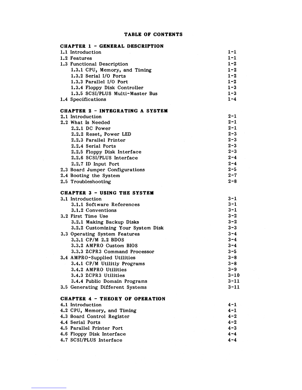
Ampro Little Board/PLUS User manual

COMPUTERS,
INCORPORATED
LITTLE BOARD/PLUS
TECHNICAL
MANUAL
Part
Number:
A74010
Revision: B
67
East
Evelyn
Ave
.•
Mountain
View,
CA
94041
• (415)962-0230

PREFACE
This
manual
is
for
integrators
of
systems
based
on
Little
Board/PLUS.
It
contains
information
on
hardware
requirements
and
interconnection,
and
details
of
how
to
use
the
system.
There
are
five
chapters,
organized
as
follows:
Chapterl-
GENERAL
DESCRIPTION:
General
information
pertaining
to
the
Little
Board/PLUS,
its
major
features,
and
a
brief
functional
description
of
the
board.
Chapter
2 - INTEGRATING A SYSTEM:
Descriptions
of
the
external
components
necessary
to
construct
a
CP/M-based
system
with
floppy
and
hard
disk
drives.
Included
are
tables
listing
the
pinouts
of
each
of
the
six
board
connectors,
as
well
as
features
and
special
considerations
concerning
the
board's
peripheral
interfaces.
Chapter
3 -
USING
THE SYSTEM:
System
power-up
procedures,
and
operation
with
AMPRO's
enhanced
CP/M
operating
system
and
utilities.
Chapter
4 -
THEORY
OF
OPERATION:
Detailed
technical
information
on
Little
Board/PLUS
hardware.
Chapter
5 -
PROGRAMMER'S
REFERENCE:
I/O
port
addresses
and
programming
information
regarding
custom
programming
of
Little
Board/PLUS.
Only
brief
descriptions
and
instructions
regarding
the
Little
Board/PLUS
system
software
are
provided
in
this
manual.
For
full
details
on
the
AMPRO-
supplied
system
software,
please
refer
to
the
Z80
System
Software
User's
Manual
(AMPRO
part
number
A74006).
PLEASE NOTE
Specifications
are
subject
to
change
without
notice.
The
contents
of
this
document
are
believed
to
be
accurate.
If
errors
are
found,
please
notify
AMPRO
COMPUTERS INC.,
at
the
address
shown
on
the
title
page
of
this
document.
The
following
is
a
list
of
trademarks
used
within
this
document:
Z80: Zilog,
Inc.
CP/M:
Digital
Research,
Inc.
mM:
International
Business
Machines
ZCPR3:
Richard
L.
Conn
LITTLE
BOARD,
LITTLE Board/PLUS, SCSI/PLUS:
AMPRO
Computers,
Inc.
No
part
of
this
document
may
be
reproduced
in
any
form,
for
commercial
purposes
without
the
express
written
consent
of
AM
PRO
Computers,
Inc.
Copyright
(C)
1985,
A.PRO
COMPUTERS INCORPORATED

TABLE OF
CONTENTS
CHAPTER 1 - GENERAL DESCRIPTION
1.1
Introduction
1.2
Features
1.3
Functional
Description
1.3.1
CPU,
Memory,
and
Timing
1.3.2
Serial
I/O
Ports
1.3.3
Parallel
I/O
Port
1.3.4
Floppy
Disk
Controller
1.3.5
SCSI/PLUS
Multi-Master
Bus
1.4
Specifications
CHAPTER
2 -
INTEGRATING
A SYSTEM
2.1
Introduction
2.2
What
Is
Needed
2.2.1
DC
Power
2.2.2
Reset,
Power
LED
2.2.3
Parallel
Printer
2.2.4
Serial
Ports
2.2.5
Floppy
Disk
Interface
2.2.6
SCSI/PLUS
Interface
2.2.7
ID
Input
Port
2.3
Board
Jumper
Configurations
2.4
Booting
the
System
2.5
Troubleshooting
CHAPTER
3 - USING THE SYSTEM
3.1
Introduction
3.1.1
Software
References
3.1.2
Conventions
3.2
First
Time
Use
3.2.1
Making
Backup
Disks
3.2.2
Customizing
Your
System
Disk
3.3
Operating
System
Features
3.3.1
CP/M
2.2
BDOS
3.3.2
AMPRO
Custom
BIOS
3.3.3
ZCPR3
Command
Processor
3.4
AMPRO-Supplied
Utilities
3.4.1
CP/M
Utilitiy
Programs
3.4.2
AMPRO
Utilities
3.4.3
ZCPR3
Utilities
3.4.4
Public
Domain
Programs
3.5
Generating
Different
Systems
CHAPTER
4 - THEORY OF OPERATION
4.1
Introduction
4.2
CPU,
Memory,
and
Timing
4.3
Board
Control
Register
4.4
Serial
Ports
4.5
Parallel
Printer
Port
4.6
Floppy
Disk
Interface
4.7
SCSI/PLUS
lnterface
1-1
1-1
1-2
1-2
1-2
1-2
1-3
1-3
1-4
2-1
2-1
2-1
2-3
2-3
2-3
2-3
2-4
2-4
2-5
2-7
2-8
3-1
3-1
3-1
3-2
3-2
3-3
3-4
3-4
3-4
3-5
3-8
3-8
3-9
3-10
3-11
3-11
4-1
4-1
4-2
4-2
4-3
4-4
4-4

CHAPTER
5 - PROGRAMMERS' REFERENCE
5.1
Introduction
5.2
ZSOA
CPU
5.3
Memory
5.4
Board
Control
Register
5.5
Counter/Timer
Circuit
5.6
Serial
Ports
5.7
Baud
Rate
Generation
5.S
Floppy
Disk
Interface
5.9
Parallel
Printer
Port
5.10
ID
Input
Port
5.11
SCSI/PLUS
Interface
5.11.1
SCSI (SASI)
Programming
5.11.2
Simple
Bidirectional
I/O
5-1
5-1
5-1
5-2
5-3
5-3
5-4
5-5
5-5
5-5
5-6
5-6
5-7
APPENDIX
A - BOARD
DIAGRAM,
PARTS
LIST,
AND
SCHEMATIC
APPENDIX
B -
TYPICAL
INTERFACE
CABLES
APPENDIX
C -
USER
GROUPS
ApPENDIX
D - COMPONENT
DATA
SHEETS

CHAPTER
1
GENERAL
DESCRIPTION
1.1
INTRODUCTION
This
chapter
provides
an
overview
and
functional
description
of
the
AMPRO
Little
Board/PLUS
single
board
computer.
It
is
intended
to
provide
a
basic
understanding
of
the
Little
Board/PLUS,
and
how
it
forms
the
basis
of
a
compact,
powerful
computer
system.
1.2
FEATURES
Little
Board/PLUS
is
a
complete
8-bit,
Z80-based
single
board
microcomputer.
It
includes
all
the
circuitry,
software,
and
firmware
necessary
to
construct
a
functional
CP/M-based
computer
system.
Some
of
the
main
features
are:
.4MHz
Z80A
8-bit
microprocessor
• 64K
bytes
dynamic
RAM,
4K
-32K
EPROM
•
Two
spare
counter/timer
channels
• Floppy
controller
capable
of
controlling
from
one
to
four
single-
or
doubl~-sided,
single-
or
double-density,
40-
or
80-track
mini
or
micro
floppy
drives
•
Two
RS232C
serial
ports
•
One
Centronics
printer
port
• SCSI/PLUS
multi-master
I/O
expansion
bus:
• SASI
Disk/Tape
controller
compatible
•
ANSC
X3T9.2 (SCSI)
compatible
•
Multiple
Little
Board
networking
•
Simple
bi-directional
I/O (17
lines)
• Mounts
directly
to
a
5-1/4"
disk
drive
• Minimum
external
components
•
Power
connector
and
voltages
compatible
with
5-1/4
inch
disk
drives
1.3
FUNCTIONAL
DESCRIPTION
The
following
paragraphs
briefly
describe
the
Little
Board/PLUS
single
board
computer.
More
detailed
information
can
be
found
,in
Chapter
4,
Theory
of
Operation.
1-1

1.3.1
CPU,
Memory,
and
Timing
The
heart
of
the
Little
Board/PLUS
is
a Z80A
8-bit
microprocessor
operating
at
4 MHz. All
system
functions
are
based
on
a
single
16
MHz
master
clock.
System
RESET
is
provided
in
two
ways:
upon
power-up
and
via
an
external
RESET
switch.
Two
types
of
memory
are
present:
EPROM
and
RAM.
A
single
28-pin
EPROM
socket
provides
from
4K
to
32K
bytes
of
firmware
space.
Jumpers
are
used
to
program
the
socket
for
a
2732,
2764,
27128,
or
27256
type
EPROM.
The
EPROM
can
be
enabled
and
disabled
by
software.
System
RAM
consists
of
eight
64k
x 1
bit
dynamic
RAM
devices.
Control
circui-
try
for
the
RAM
memory
is
entirely
digital
(no
one-shots
or
R-C
components)
and
provides
a
high
degree
of
reliability.
A
ZSO
Counter
Timer
Circuit
(CTC)
provides
four
programmable
counter
or
timer
channels.
Two
of
the
CTC
channels
provide
the
baud
rate
clocks
used
by
the
two
serial
I/O
ports.
The
other
two
CTC
channels
are
available
for
use
as
programmable
timers
in
applications
programs,
for
real-time
clock
functions,
etc.
1.3.2
Serial
Ports
A Z-SO
Dual
Asynchronous
Receiver/Transmitter
(DART)
provides
two
fully
pro-
grammable
serial
I/O
ports.
Each
channel
has
four
of
the
standard
RS232C
signals:
TxD, RxD, RTS,
and
CTS.
These
signals
are
sufficient
for
interfacing
most
serial
printers,
modems,
and
terminals.
In
those
cases
where
other
interface
signals
are
required
for
one
of
the
serial
ports,
handshaking
·signals
can
be
borrowed
from
the
second
port
(if
not
needed
by
that
port).
Polarity
and
use
of
the
handshaking
signals
is
defined
by
the
software.
Programmable
baud
rate
clocks
are
supplied
by
the
CTC
for
baud
rates
up
to
9600
baud.
Additional
circuitry
provides
baud
rates
of
19.2K
and
3S.4K
baud,
for
Port
A
only.
Since
the
two
serial
ports
are
otherwise
identical,
either
can
be
programmed
as
a
terminal,
modem,
serial
printer,
or
other
RS232C
inter-
face.
1.3.3
Parallel
Printer
Port
The
parallel
printer
port
provides
the
10
essential
signals
of
a
Centronics-
type
printer
interface:
Data
Bits
I-S,
Data
Strobe,
and
Busy.
Both
the
Data
Strobe
(output)
and
Busy
(input)
handshake
protocols
are
defined
by
software.
1.3.4
Floppy
Disk
Controller
A
Western
Digital
1772
floppy
disk
controller
device
provides
all
of
the
functions
required
to
interface
with
standard
5-1/4
inch
"mini"
--
and
most
3
to
4
inch
"micro"
--
floppy
disk
drives.
The
1772
includes
the
following
capabilities
within
a
single
LSI
device:
1-2

•
Digital
phase
locked
loop
•
Digital
write
precompensation
•
Motor
on
start/stop
delay
•
Software
controlled
step
rates
Timing
for
the
floppy
disk
interface
is
derived
directly
from
the
8
MHz
system
.
clock,
without
delay
lines,
R-C
time
constants,
or
one-shots.
This
again
results
in
a
very
high
degree
of
system
reliability.
1.3.5
SCSI/PLUS
Multi-Master
Bus
A
50-pin
"ribbon
cable
bus"
interface
which
meets
the
specifications
for
the
popular
Small
Computer
System
Interfaces
(SCSI)
--
formerly
called
"SASI"
--
provides
a
general
purpose
multi-master
I/O
expansion
bus.
All SCSI
Initiator
and
Target
functions
are
fully
supported,
including
bus
arbitration
and
dis-
.
connect/reselect.
In
addition,
Little
Board/PLUS
supports
the
Initiator
function
of
AMPRO's
innovative
SCSI/PLUS
extension
to
SCSI.
This
allows
connection
of
up
to
64
SCSI/PLUS
Target
devices,
rather
than
the
usual
eight
device
limit
of
SCSI.
Applications
include
both
direct
and
shared
use
of
a
wide
variety
of
control-
lers
and
devices,
as
well
as
tightly
coupled
Little
Board
networks.
For
example,
one
or
more
Little
Boards,
an
SCSI
Winchester
controller,
and
modules
providing
calendar/clock,
serial
port
expansion,
RAM
disk,
etc.,
might
all
coexist
on
the
same
SCSI/PLUS
bus.
The
17
bidirectional
I/O
signals
of
the
SCSI/PLUS
interface
may
also
be
used
as
general
purpose
software-controlled
digital
I/O
lines,
without
SCSI
compa-
tibility.
In
this
case
the
board's
8-bit
SCSI
bus
ID
input
register
can
serve
as
an
additional
8-bit
input
port.
1-3

1.4
LITTLE BOARD/PLUS SPECIFICATIONS
CPU:
MEMORY:
TIMER:
SERIAL
I/O:
4MHz Z80A,
8-bit
microprocessor
64
kilobytes
of
dynamic
RAM
4-32
kilobytes
of
EPROM
Z80A CTC (4
channels)
2
channels
not
used
by
AMPRO
software
Z80A
Dual
Asynchronous
Receiver/Transmitter
(DART)
Two
-RS232C
compatible
ports:
DB-25
female
conns.
Software-controlled
baud
rates:
Channel
A - 75
to
38,400
baud
Channel
B - 75
to
9600
baud
Four
standard
RS232C
signals
per
port:
Data
Out
Data
In
Handshake
Out
Handshake
In
Two
Ground
pins
PARALLEL
I/O:
Centronics-compatible
printer
port
10
signals
supported:
Data
Bits
1-8
-
output
Data
Strobe
-
output
Printer
Busy -
input
12
Ground
pins
DISK
I/O:
No.
drives
supported:
1 - 4
Disk
Controller:
WD1772
Data
rate:
250k
bps
(MFM), 125K
bps
(FM)
Sector
size:
128,
256,
512,
or
1024
bytes
Phase
locked
loop:
digital
(8 mHz)
Write
precompensation:
software
enabled
Drive
capacity
(formatted):
SCSI/PLUS
BUS
INTERFACE:
Type
1 (40
track,
1-sided)
-200K
bytes
Type
2 (40
track,
2-sided)
-400K
bytes
Type
3 (80
track,
1-sided)
-400K
bytes
Type
4 (80
track,
2-sided)
-800K
bytes
SASI
Compatible
ANSI
X3T9.2
(SCSI)
compatible
SCSI/PLUS
Initiator
compatible
Uses
NCR
5380
SCSI
bus
controller
POWER:
Same
power
connector
and
voltabes
as
mini
and
micro
floppy
disk
drives.
Power
Requirements:
+5VDC
at
O.95A
+9
to
12VDC
at
0.05A
ENVIRONMENT:
Temperature:
0
to
32
degrees
C,
operating
Humidity:
5
to
9596,
non-condensing
Altitude:
0-10,000
feet
1-4

SIZE: '
SOFTWARE:
7.75 x
5.75
x
0.75
inches
Boot
program
in
2732
EPROM
CP/M
Version
2.2
and
BIOS
on
diskette
Little
Board/Plus
system
utilities
Option:
FRIENDLY
Integrated
Operating
Environment
Option:
BIOS
and
Utilities
source
code
DOCUMENTATION:
Little
Board/Plus
Technical
Manual
Little
Board/Plus
Software
Manual
Option:
SCSI/PLUS
Technical
Specification
1-5


CHAPTER
2
INTEGRA
TING
A
SYSTEM
2.1
INTRODUCTION
This
chapter
describes
what
is
required
to
build
a
floppy
or
hard
disk
based
computer
system
using
Little
Board/PLUS
as
the
heart
of
the
machine.
Details
are
provided
concerning
external
device
requirements,
the
boards
connector
pinouts,
how
to
prepare
the
board
for
use,
and
connection
of
peripherals
such
as
terminals,
printers,
and
modems.
Refer
to
Appendix
B
for
tables.
2.2
WHAT
IS
NEEDED
A
very
minimum
number
of
external
parts
will
turn
the
Little
Board/PLUS
circuit
board
into
a
very
powerful
computer
system.
The
items
listed
in
Table
2-1
are
easily
available
components.
Item
Floppy
drive(s)
SCSI (SASI)
hard
disk
controller
(option)
Hard
disk
drive(s)
(option)
Power
supply
Reset
switch
Cables
Cabinet
Table
2-1.
System
Components
Description
1
to
4 mini
or
micro
floppy
drives,
40
or
80
track,
single-
or
double-sided
Adaptec
ACB-4000
or
Xebec
1410(A),
or
equivalent
SCSI (SASI)
hard
disk
controller
5
to
20
Megabyte
drive(s);
must
be
compatible
with
your
specific
SCSI (SASI)
controller
+12VDC @ 2.0A,
+5
VDC
@ 2.5A (2
floppies);
additional
power,
as
required
for
hard
disk
options
SPST,
normally
open,
w/LED
indicator
Serial
(2),
parallel,
floppy,
SCSI,
and
power
cables
for
Little
Board/PLUS
and
drives
Housing
for
completed
system
Figure
2-1
shows
the
Little
Board/PLUS
interface
connectors.
All
components
can
be
housed
in
a
very
small
box.
The
size
is
determined
primarily
by
the
disk
drives,
and
perhaps
the
power
supply.
A
space
of
approximately
7 x 8 x
11
inches
is
adequate
for
a
dual
floppy
system.
Tables
2-2
through
2-7
list
the
cable
connector
pinouts
for
the
board's
interface
connectors.
Table
2-2
provides
suggested
mating
connectors
and
manufacturers'
part
numbers.
2-1

Table
2-2.
External
Connector
Part
Numbers
Board
Function
Part
Number
Connector
J1
Power
Connector
Housing:
AMP
1-480424-0
Contacts:
AMP
60619-1
(4
req.)
J2
Parallel
Printer,
3M:
3399-6000
Board
end
T&B:
609-2601M
Molex:
15-29-8262
Parallel
Printer,
AMP:
57F-30360
Printer
end
3M:
3366-1001
T&B:
609-36M
J3,4
Serial
Ports
A,B
Housing:
Molex
22-01-2067
Contacts:
Molex
08-50-0114
(6
req.)
J5
RESET,
Power
LED
Housing:
Molex
22-01-2047
Contacts:
Molex
08-50-0114
(4
req.)
J6
Floppy
Disk
Interface
3M:
3463-0001
(Card
edge
connectors)
T&B:
609-3415M
Molex:
15-29-0341
J8
SCSI/PLUS
Interface
T&B:
609-5000M
Molex:
15-29-8502
Berg:
66902-150
NOTE
All
Little
Board/PLUS
s,oftware
is
distributed
on
double-
sided
48
tpi
AMPRO
format
mini
floppy
diskettes.
This
may
be
directly
read
from,
or
booted,
in
either
a
48
or
96
tpi
mini
floppy
drive.
The
only
special
requirement
for
first
time
booting
of
the
system
is
that
you
have
a
double-sided
48
or
96
tpi
mini
floppy
drive
capable
of
stepping
at
a 6
mS
step
rate,
and
a
terminal
capable
of
9600
baud
opera-
tion.
Once
you
have
initially
booted
the
system,
you
may
then
generate
a
system
disk
with
alternative
defaults,
e.g.,
single-sided,
micro
floppy,
12
mS
step
rate,
19.2K
baud
terminal
data'
rate,
etc.
2-2

PARALLEL PRINTER
J
.0
---POWER
o
•
~~---
SERIAL A
SERIAL B
~-+----
RESET. POWER LED
-
...
---
FLOPPY
'-----
m
INPUT
Figure
2-1.
Little
Board/PLUS
Connector
Locations.
2-3

2.2.1
DC
Power
The
power
connector
(Jl)
pinout
is
identical
with
that
of
the
power
connectors
on
nearly
all
5
-1/4
inch
floppy
disk
drives.
Note
that
pin
1
on
Jl
is
reversed
from
the
other
connectors
on
the
same
end
of
the
board.
Refer
to
Table
2-3
for
power
connections.
CAUTION
BE
SURE
THE
POWER
PLUG
IS
CORRECTLY
WIRED
BEFORE
ATTEMPTING TO APPLY
POWER
TO
THE BOARD.
Table
2-3.
Power
Connections
(.11)
Pin
Signal
Name
Function
1 +12VDC
+6
to
+ 15VDC
2
Ground
Ground
return
3
Ground Ground
return
4 +5VDC +5VDC
+/-
5%
2.2.2
RESET,
Power
LED
This
connector
is
for
connection
to
an
external
SPST
switch,
to
provide
the
master
RESET
signal.
In
addition,
a 15
rnA
current
source
provides
power
to
an
LED
power-on
indicator.
Refer
to
Table
2-4
for
the
pinout
of
connector
J5.
Table
2-4.
RESET,
Power
LED
Connector
(.15)
Pin
Signal
Name
Function
1
Ground
To
LED
Cathode
2
LED
To
LED
Anode
3
Ground
To
one
side
of
RESET
switch
4 RESET To
other
side
of
RESET
switch
2.2.3
Serial
Ports
Table
2-5
lists
the
connector
pinout
and
signal
definitions
for
each
of
the
two
RS232C
serial
I/O
ports.
Serial
Port
A
is
board
connector
J3,
and
Serial
Port
B
is
board
connector
J4.
Appendix
B
gives
typical
cable
wiring
for
connection
to
terminals,
serial
printers,
and
modems.
2-4

Table
2-5.
Serial
Connectors
(.13/.14)
Pin
Signal
Name
Function
in/out
DB-25
Pin
(DCE)
1
Ground
Protective
Ground
--
1
2
Ground
Signal
Ground
--
7
3 TxD
Data
Output
out
3
4
HSO
Hand
Shake
Out
(RTS)
out
5
5 RxD
Data
Input
in
2
6 IISI
Hand
Shake
In (CTS)
in
20
2.2.4
Parallel
Printer
The
Little
Board/PLUS
parallel
printer connector
has
a
pinout
that
allows
the
use
of
flat
ribbon
cable
between
the
J2
header
and
the
first
26
lines
of
a 36
pin
male
Centronics-type
connector
at
the
printer
end.
Refer
to
Table
2-6
for
the
printer
connector's
pinout
and
signal
definitions.
Note
that
the
pin
numbering
convention
for
the
board's
header
connector
(J2)
differs
from
that
of
Centronics
connectors,
even
though
the
required
inter-
connection
cable
is
straight
through.
To
clarify
this,
each
signal's
corres-
ponding
Centronics
connector
pin
number
has
been
included
in
Table
2-6.
Table
2-6.
Parallel
Printer
Connector
(.12)
J2
Signal
Name
Function
in/out
Printer
Pin Pin
1 -DS
Data
Strobe
out
1
3
Data
1
LSB
of
printer
data
out
2
5
Data
2 · · 3
· ·
7
Data
3 · · 4
· ·
9
Data
4 · · 5
· ·
11
Data
5 · · 6
· ·
13
Data
6 · · 7
· ·
15
Data
7 · · 8
· ·
.17
Data
8
MSB
of
printer
data
out
9
19
---
(Not
used)
21
BUSY
Printer
BUSY
in
11
23
---
(Not
used)
25
---
(Not
used)
2-22
(even)
Signal
grounds
19-29
24,26
---
(Not
used)
30,31
Appendix
8
provides
a
wlrmg
table
for
a
cable
which
will
work
with
most
Centronics
compatible
printers.
The
cable
required
is
identical
to
that
used
with
the
Tandy
(Radio
Shack)
TRS-80
Model
100
portable
computer.
The
Tandy
cable
part
number
is
26-1409.
2-5

2.2.5
Floppy
Disk
Interface
Table
2-7
lists
the
Goppy
disk
drive
interface
connector
(J6)
pinout
and
signals.
A
single
34-conductor
PC
edgecard
connector
goes
at
the
Little
Board
end,
while
there
can
be
from
1
to
4
PC
card
edge
connectors
for
connecting
mini
floppy
disk
drives.
Micro
Goppy
drives
generally
use
34-conductor
header
connectors,
instead.
Table
2-7.
Floppy
Disk
Interface
Connector
("'6)
Pin
Signal
Name
Function
in/out
2
-LOW
SPEED
Speed
select
(option)
out
4
---
(Not
used)
--
6 -DRIVE
DEL
4
Drive
Select
4
out
8 -INDEX
Index
pulse
in
10
-DRIVE
SEL
1
Drive
Select
1
out
12
-DRIVE
SEL
2
Drive
Select
2
out
14
-DRIVE
SEL
3
Drive
Select
3
out
16
-MOTOR
ON
Motor
on
control
out
18
-DIR
SEL
Direction
select
out
20
-STEP
Step
out
22 -WRITE DATA
Write
data
out
24 -WRITE GATE
Write
gate
control
out
26
-TRACK 00
Track
00
in
28
-WRITE PRT
Write
protect
in
30
-READ DATA
Read
data
in
32 -SIDE
ONE
Side
select
out
34 -READY
Drive
ready
(option)
in
1-33
(all
odd
pins)
Signal
grounds
--
Nearly
any
type
of
soft-sectored,
single-
or
double-sided,
40-
or
80-track,
mini
(5
1/4")
or
micro
(3"
to
4")
floppy
disk
drive
is
usable
with
the
Little
Board.
Naturally,
the
higher
the
quality
of
the
drives
you
use,
the
better
your
system's
reliability.
Here
are
some
things
that
may
be
helpful
for
you
to
know:
•
As
indicated
earlier
in
this
chapter,the
default
system
parameters
programmed
on
the
standard
Little
Board/PLUS
system
disk,
as
shipped,
require
that
drive
A
be
a
double-sided
48
or
96
tpi
mini
floppy
drive,
with
6
mS
(or
faster)
stepping
rate.
Once
you
have
booted
that
disk,
you
can
create
a
new
system
disk
with
alternative
defaults,
allowing
you
to
subsequently
boot
from
any
other
system-compatible
drive.
•
The
drives
used
must
be
compatible
with
the
AMPRO
floppy
disk
inter-
face
(see
Table
2-7).
This
interface
is
generally
referred
to
as
SA-
450
compatible.
• Use
of
high
quality
floppy
disk
drives
is
recommended;
preferably
having
DC
servo-controlled
direct
drive
motors.
•
The
drives
must
be
capable
of
12
mS
(or
faster)
stepping.
2-6

• More
than
one
type
of
floppy
disk
drive,
up
to
four,
can
be
present
in
the
system,
and
in
any
mix.
•
Each
disk
drive
must
be
jumpered
for
a
specific
Drive
Select
value,
1
through
4.
Drive
A
is
1,
B
is
2,
etc.
•
Resistive
terminations
should
be
installed
only
on
the
drive
connected
to
the
last
interface
cable
connector
(farthest
from
the
computer).
• When
using
drives
with
a
Head
Load
option,
jumper
the
drives
for
"head
load
with
motor
on"
rather
than
"head
load
with
drive
select"
jumpering.
2.2.6
SCSI/PLUS
Interface
The
SCSI/PLUS
interface
(J8)
uses
a
50-pin
male
header
connector
to
interface
with
SCSI-compatible
peripherals.
Table
2-8
shows
the
signal
names
and
pin
numbers
for
the
SCSI/PLUS
bus
interface
connector.
Refer
to
your
disk
con-
troller
documentation,
or
the
ANSI
SCSI
(X3T9.2)
specification,
for
infor-
mation
on
the
signal
functions.
Table
2-8.
SCSI
Interface
Connector
(.18)
Pin
Signal
Function
1 -
49
(All
odd
pins)
Signal
grounds
2
-DBO
Data
Bit
0
(LSB)
4
-OBI
" " 1
6 -DB2 " " 2
8 -DB3 " " 3
10
-DB4 " " 4
12
-DB5 " " 5
14
-DB6 " " 6
16
-DB7 " " 7
(MSB)
18
-DBP
Data
Parity
20,22,24
Ground
Signal
Ground
25
---
(Not
used)
26 TERMPWR
Termination
+5
VDC
28,30
Ground
Signal
Ground
32
-ATN
Attention
34
Ground
Signal
Ground
36 -BSY
Busy
38 -ACK
Transfer
Acknowledge
40
-RST
Reset
42 -MSG
Message
44 -SEL
Select
46
-C/D
Control/Data
48
REQ
Transfer
Request
50
-I/O
Data
direction
2-7

This
interface
can
serve
a
variety
-of
purposes,
including
connection
of
hard
disk
controllers,
tape
controllers,
printer
and
communication
servers,
etc.
In
addition,
the
interface
signals
may
be
used
as
direct
input/output
lines,
allowing
the
connection
of
TTL-level
interfacing
devices
and
sensors,
etc.
The
output
signals
are
open
collector,
48mA
drivers,
and
may
be
enabled
and
disabled
under
software
control.
On-board
removable
resistor
networks
provide
bus
termination.
2.2.1
ID
Input
Port
Eight
pairs
of
jumper
pins
(J
7)
provides
an
ID
Input
Port,
which
can
be
used
by
SCSI-related
software
to
determine
the
board's
SCSI
bus
ID
for
bus
arbitra-
tion
(or
other)
purposes.
If
not
required
for
this
purpose
the
ID
Input
Port
can
be
used
as
a
general
purpose
8-bit
input
port
connector,
with
a
flat
ribbon
cable
connector
plugged
onto
J7.
Table
2-9
shows
the
signal
names
and
pin
numbers
for
J7.
Table
2-9.
ID
Input
Port
(
...
1)
Pin
Signal
Function
1 -ID7 ID
Bit
7
(MSB)
3 -ID6 " " 6
5 -ID5 " " 5
7 -ID4 " " 4
9 -ID3 " " 3
11
";ID2
" " 2
13
-IDI
" " 1
15 -IDO " " o
(LSB)
2-16
Ground
Signal
Ground
2.3
BOARD
JUMPER
CONFIGURATIONS
Little
Board/PLUS
contains
nine
sets
of
jumpers,
which
may
be
used
to
customize
the
board's
operation.
The
jumper
sets
consist
of
either
two
or
three
pins,
with
pin
1 a
square
pad;
each
jumper
set
is
outlined
with
white
boxes
on
the
component
side
of
the
"board.
The
options
available
through
these
jumpers
are
described
in
the
following
paragraphs.
NOTE
Do
not
solder
wires
to
the
jumper
pins,
as
this
may
void
your
board's
warranty.
Use
wire
wrap,
or
snorting
plugs
instead.
2-8

For
normal
operation,
no
jumper
setup
is
required.
All
of
the
jumper
settings
are
factory-set,
by
means
of
shorting
plugs
on
the
pins,
or
traces
on
the
bottom
side
of
the
board.
Use
of
J7
(SCSI
bus
ID)
varies,
according
to
software
requirements.
AMPRO's
standard
hard
disk
software
does
not
require
the
use
of
J7.
"IIPI
-
Clock
This
jumper,
when
shorted,
connects
the
system
16
mHz
master
clock
bus
to
the
16
mHz
hybrid
oscillator
(U2).
It
is
intended
for
test
purposes
only.
FACTORY SETTING:
shorted
"IIP2
-CTC
CLK/TRG3
This
jumper
connects
the
CTC's CLK/TRG3
input
(JMP2-2)
to
either
the
1772
FDC's
interrupt
request
output
signal
(JMP2-3)
or
to
the
CTC's
ZC/TC2
output
signal
(JMP2-1).
FACTORY SETTING:
both
options
open
JIIP3
-CTC
CLK/TRG2
This
jumper,
when
shorted,
connects
the
5380
SCSI
controller's
interrupt
request
output
signal
(JMP3-2)
to
the
CTC'S CLK/TRG2
input
(JMP3-1).
FACTORY SETTING:
open
JMP4 -
U6
Option
This
jumper
is
shorted
for
8 mHz
-only
operation
of
the
1772
FDC
device.
NOTE:
If
this
jumper
is
shorted,
the
clock
multiplexor
IC,
U6
must
not
be
present;
if
U6
is
present,
this
jumper
must
be
open.
FACTORY SETTING:
open
(U6
present)
JMP5,6
-
EPROM
Type
These
jumpers
are
used
to
program
the
board
for
various
types
of
EPROM
devices.
These
two
jumpers
are
set
as
shown
in
Table
2-10.
2-9

Table
2-10.
EPROM
Jumper
Configurations
EPROM
Type
JMP5:
1-2
JMP5:
2-3
JMP6
2732
open
short
*
2764 * *
open
27128
short
open
open
27256
short
open
short
Factory
setting:
open
short
open
Notes
(1)
Items
indicated
by
*
can
be
open
or
shorted;
however
do
not
short
both
JMP5
options
simultaneously.
(2) When a 2732
24-pin
EPROM
is
used,
it
must
be
plugged
into
the
lower
24
pins
of
the
28-pin
EPROM
socket,
so
that
the
2732's
pin
1
plugs
into
pin
3
of
the
socket.
dMP7
-
DART
RIA
This
jumper,
when
shorted,
connects
the
1772
FDC's
DRQ
output
singal
(JMP7-2)
to
the
DART's
RIA
input
(JMP7-1).
FACTORY SETTING:
open
dllP8
-
DART
DCDA
This
jumper,
when
shorted,
connects
the
5380
SCSI
controller's
DRQ
output
singal
(JMP8-1)
to
the
DART's
RIA
input
(JMP8-2).
FACTORY SETTING:
open
dllP9
-
SCSI
Termination
Power
This
jumper,
when
shorted,
connects
the
board's
+5V
DC
power
to
the
SCSI
bus
signal
line
provided
for
optional
external
termination.
FACTORY SETTING:
open
2-10
Table of contents
Other Ampro Single Board Computer manuals
Popular Single Board Computer manuals by other brands

SMART Embedded Computing
SMART Embedded Computing ATCA-8310 quick start guide

Portwell
Portwell WUX Series user guide

Cherry
Cherry theobroma systems JAGUAR SBC-RK3588-AMR user manual

Arbor Technology
Arbor Technology EmCORE-i65M3 user manual

pandaboard
pandaboard OMAP4460 Pandaboard ES System reference manual

EVOC
EVOC EC4-1812CLDNA manual