Eltek Valere THEIA S User manual
357100.013
Solar Grid-Tie Inverters
2.1kW to 4.6kW
User’s Guide
THEIA S
String Inverters
2User’s Guide THEIA S String Inverters 357100.013, Issue 2.0, 2010 Aug
Information in this document is subject to change without notice and does not represent a
commitment on the part of Eltek Valere.
No part of this document may be reproduced or transmitted in any form or by any means —
electronic or mechanical, including photocopying and recording — for any purpose without the
explicit written permission of Eltek Valere.
Copyright ©:
Eltek Valere
, 2011
357100.013 Issue 2.0, 2010 Aug
Published 2010-08-27
MfH
NS-EN ISO 14001 Certified
Certificate No:
11276-2007-AE-NOR-NA
NS-EN ISO 9001 Certified
Certificate No:
4072-2007-AQ-NOR-NA

User’s Guide THEIA S String Inverters 357100.013, Issue 2.0, 2010 Aug 3
Table of Contents
1. Symbols .......................................................................................4
Warning Notices..............................................................................................4
2. Safety, Dangers and Intended Use ............................................5
3. Function .......................................................................................6
Variants...........................................................................................................6
Options ...........................................................................................................6
4. Installation ...................................................................................7
Scope of delivery ............................................................................................7
Unpacking.......................................................................................................7
Mounting the Inverter ......................................................................................8
Connecting the Inverter.................................................................................11
5. Startup........................................................................................17
Initial Startup of a Single Inverter..................................................................18
Replacing Devices ........................................................................................22
6. Operation ...................................................................................24
DC Disconnector...........................................................................................24
Display and Operation ..................................................................................25
Standard Display...........................................................................................27
Main Menu ....................................................................................................27
Operating Display .........................................................................................28
Settings.........................................................................................................31
Information....................................................................................................37
Error Display .................................................................................................41
7. Service........................................................................................44
Service Menu................................................................................................44
8. Maintenance...............................................................................48
Maintenance .................................................................................................48
Cleaning........................................................................................................49
9. Placing Out of Operation ..........................................................50
Dismounting..................................................................................................50
Return Consignment .....................................................................................51
10. Disposal .....................................................................................53
11. Troubleshooting ........................................................................54
Table of events .............................................................................................54
12. Standards and Approvals .........................................................56
13. Technical Data ...........................................................................57
14. EU Declaration of Conformity ..................................................59
15. Warranty for
THEIA S
................................................................60
4User’s Guide THEIA S String Inverters 357100.013, Issue 2.0, 2010 Aug
1.Symbols
Warning Notices
Classification of warning notices
The warning notices differentiate between three types of dangers indicated by the
following signal words:
•Caution warns of material damage
•Warning warns of bodily harm
•Danger warns of a danger to life
Layout of the warning notices
Type and source of the danger!
•Action to avoid the danger
Signal words

User’s Guide THEIA S String Inverters 357100.013, Issue 2.0, 2010 Aug 5
2.Safety, Dangers and Intended Use
Use inverters according to their intended use.
Use inverters in original and technically fully intact condition without unauthorized
modifications.
Ensure that inverters are installed and serviced by qualified specialists only.
The qualified specialist personnel requires a license from the relevant energy
suppliers.
Always mount inverters in a vertical position.
Ensure that all protection devices are fully operational.
Verify that ventilation openings are not blocked or covered.
Protect inverters from direct sunlight.
Prior to installation and maintenance work, make certain that the inverter is de-
energized.
Ensure that regulations stipulated by trade associations and inspection authorities
and agencies are observed and that the connection conditions of the relevant energy
supplier or equivalent national and international rules and regulations are adhered
to.
Observe conditions of use (see Chapter 13 Technical Data).
Use the inverter exclusively to feed photovoltaically converted solar energy into the
public 230 V/50 Hz mains.
Use the inverter exclusively in buildings or weatherproof places.
Do not use the inverter in autonomous power systems.
Do not use the inverter in vehicles.

6User’s Guide THEIA S String Inverters 357100.013, Issue 2.0, 2010 Aug
3.Function
Variants
The THEIA S String inverter line includes the following variants with different power
ranges (see Chapter 13 Technical Data):
•2100 S
•2800 S
•3100 S
•3800 S
•4300 S
•4301 S
•4600 S
•4601 S
Possible options:
•3-phase ENS (5-pole AC terminal)
with DC disconnector, or
without DC disconnector
or
•1-phase ENS-EPT (3-pole AC terminal)
with DC disconnector, or
without DC disconnector
Options
Upgrades for an inverter or an inverter system:
•Inverter networking via EIA485 bus. Much easier and more comprehensive input
and monitoring options.
•Optical and acoustical indicator (warning) devices.
•Remote monitoring or remote readout with Webmaster
•Central display of systems with Viewmaster
•Evaluation of system data with PV-Monitor

User’s Guide THEIA S String Inverters
357100.013, Issue 2.0, 2010 Aug
7
4.Installation
Scope of delivery
•
Inverter
•
Mounting fixture
•
Operating manual
•
Wieland RST 5i plug connector (3-phase ENS)
or
•
Wieland RST 3i plug connector (1-phase ENS-EPT)
Unpacking
Unpack the inverter as follows:
1. Put the box in vertical position according to box markings.
2. Cut packing straps without damaging the box.
3. Remove the cardboard sleeve.
4. Remove the lid pad.
5. Hold the inverter at the grip openings and lift it out of the base pad.
6. Put down the inverter.

8User’s Guide THEIA S String Inverters 357100.013, Issue 2.0, 2010 Aug
Mounting the Inverter
Note:
Eltek Valere
advises against installing the inverter in living spaces.
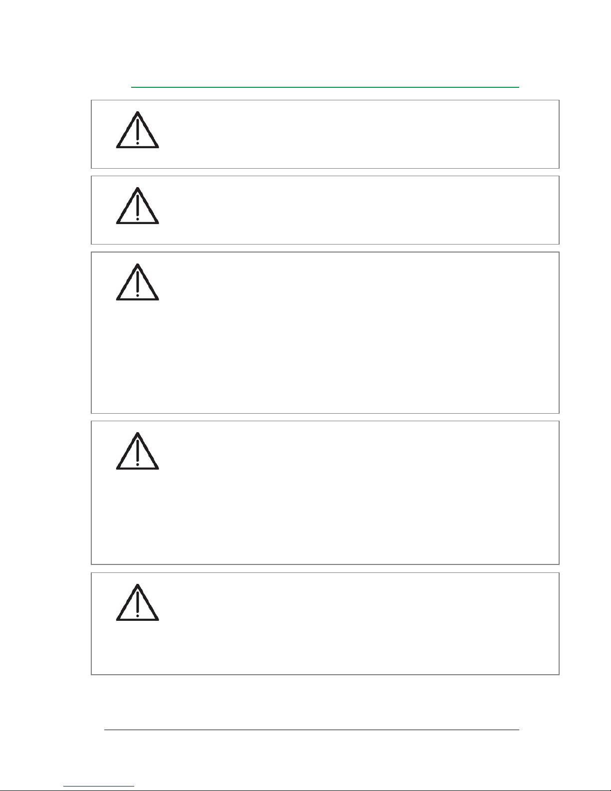
Danger to life due to electric shock!
•Have the inverter opened only by Eltek Valere service peronnel, or
service partners authorized by Eltek Valere.
Dange
r
Danger to life due to incorrect connection of inverter!
•Have inverters installed by qualified specialists only. The qualified
specialist personnel requires a license from the relevant energy suppliers.
Dange
r
Danger to life due to inverter dropping from the wall!
•Use mounting elements appropriate for the mounting wall and the weight
of the inverter unit.
•Wear protective footwear when mounting and dismounting inverters.
Dange
r
Material damage due to unprotected installation site!
•Always protect inverters with a protective roof when installing them
outdoors.
•Observe admissible ambient temperature (see
Chapter 13 Technical
Dat
a
)
.
Caution
Material damage due to excessive dust formation!
•Protection Type IP54 does not apply to the interface card.
•Avoid excessive dust formation.
•Avoid dust formation with electrically conductive dust particles.
Caution
User’s Guide THEIA S String Inverters 357100.013, Issue 2.0, 2010 Aug 9
Mounting Fixture
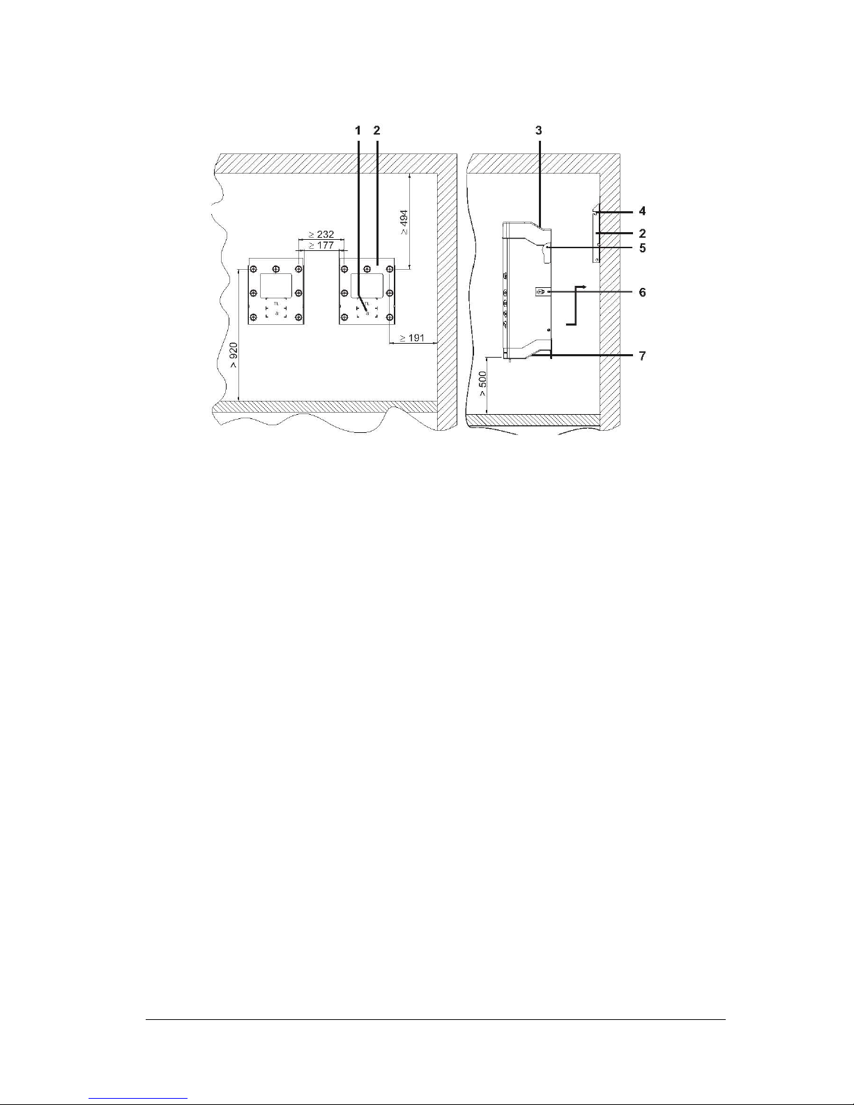
Figure 1 Distances for mounting fixture positioning
(1) Display position
(2) Mounting fixture
(3) Ventilation openings
(4) Slotted piece for mounting bolts
(5) Mounting bolts
(6) Locking screw
(7) Grip moldings
Install the mounting fixture as follows:
•Unscrew mounting fixture (2) from the back of the inverter
- Two locking screws secure the inverter in the mounting fixture
- The locking screw (6) is marked by a paper strip with a lock symbol. The
locking screw is longer than the other housing screws
- Do not remove the paper strip
•Mark the mounting holes using the mounting fixture as a template
- Observe dimensions and distances
- Observe a minimum distance of 50cm to the floor
- The display position (1) is stamped into the mounting fixture (2)
- The display position for the THEIA S series is marked with an
‘S’
•Drill the mounting holes and insert the screw anchors
•Bolt down mounting fixture (2)
10 User’s Guide THEIA S String Inverters
357100.013, Issue 2.0, 2010 Aug
Inverter
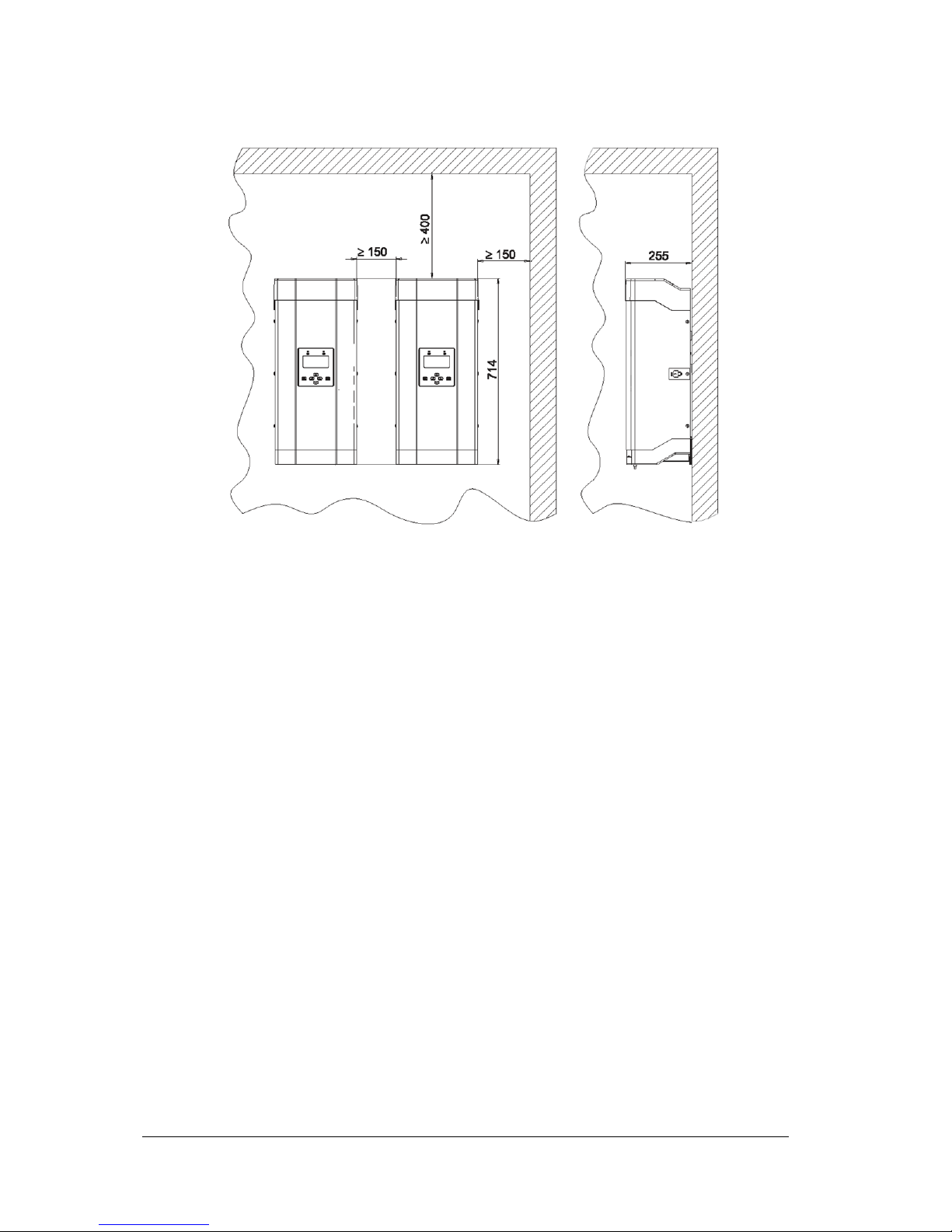
Figure 2 Spacing between mounted inverters
Mount inverters as follows:
•Observe a minimum distance of 50cm to the floor
•Slide the inverter heat sink into mounting fixture (2). Use the outer cooling fins as
guides in mounting fixture (2).
•Hold the inverter at molded grips (7) and push up until mounting bolts (5) drop into
slotted pieces (4) on both sides.
•Gently let down the inverter.
With the mounting bolts (5) seated in the slotted pieces.
•Verify that minimum distances are kept (see Figure 2)
•Verify that the inverter is hanging in the mounting fixture correctly
•Secure the inverter by inserting and tightening the locking screw (6) in the marked
position (paper strip)
•Ensure that the locking screw (6) is accessible for the dismounting of the inverter
User’s Guide THEIA S String Inverters 357100.013, Issue 2.0, 2010 Aug 11
Connecting the Inverter
Danger to life due to high AC voltage!
•Switch off the mains power supply (AC side, fuse) before connecting the
inverter.
Dange
r
Danger to life due to high AC voltage!
•Verify that galvanic isolation between the photovoltaic generator circuit
and the AC circuit is maintained by the way the cables are run.
Dange
r
Danger to life due to high DC voltage!
•Prior to connecting the inverter, verify that voltage is applied to the
generator-side DC terminal
•Prior to connecting the inverter, verify that the DC voltage polarity is
correct
•Wear insulating protective clothing and face protection if there is voltage
present at the DC input
•Remove DC cable exclusively when inverter is out of operation
Dange
r
Lack of performance and functionality due to inappropriate cables!
•Ensure that wire cross sections and fuses conform to VDE 100 Part 430,
or the equivalent local standard.
•Ensure that any network cables between two inverters are no longer than
30m
•For DC cables, use a wire cross section of at least 2.5mm2
•Ensure that the AC cable resistance does not exceed 0.5Ω
Caution
Material damage due to excessive voltage!
•Ensure that the max. DC voltage is not exceeded (see
Chapter 13
Technical Data
)
•Connect exclusively safety extra low voltage (SELV) on the contacts of
the external indicator
Caution

12 User’s Guide THEIA S String Inverters 357100.013, Issue 2.0, 2010 Aug
Terminal Side: 3-Phase ENS
Figure 3 Inverter Terminal Side: 3-phase ENS
(1) Network terminals
(2) Safety sticker
(3) DC terminal +
(4) DC terminal –
(5) Type plate
(6) Switch knob DC disconnector (optional)
(7) AC terminal
Note:
THEIA 3800S, 4300S, 4301S, 4600S
and
4601S
inverters have two pairs of DC terminals. These DC terminals are
internally paralleled.

User’s Guide THEIA S String Inverters 357100.013, Issue 2.0, 2010 Aug 13
AC Terminal: 3-Phase ENS
The Wieland RST 5i plug connector for the DC terminal is supplied with the inverter.
Figure 4 Wiring diagram (terminal side)
(1) N
(2) PE
(3) L1 (feed phase)
(4) L2
(5) L3
Terminal Side: 1-Phase ENS
Figure 5 Inverter Terminal Side: 1-phase ENS
(1) Network terminals
(2) Safety sticker
(3) DC terminal +
(4) DC terminal –
(5) Type plate
(6) Switch knob DC disconnector (optional)
(7) AC terminal
Note:
THEIA 3800S, 4300S, 4301S, 4600S
and
4601S
inverters have two pairs of DC terminals. These DC terminals are
internally paralleled.

14 User’s Guide THEIA S String Inverters 357100.013, Issue 2.0, 2010 Aug
AC Terminal: 1-Phase ENS
The Wieland RST 3i connector plug intended for the AC terminal is enclosed.
Figure 6 Wiring diagram (terminal side)
(1) N
(2) L1 (feed phase)
(3) PE
When connecting several inverters:
•Distribute inverters evenly (as regards their power) between phases of the mains
supply
AC Voltage Connection
Establish AC voltage connection as follows:
•Establish a connection to the power supply system with a cable on the AC terminal
as follows:
- with the Wieland RST 5i plug connector (3-phase ENS) supplied with the system,
or
- with the Wieland RST 3i plug connector (1-phase ENS) supplied with the system.
•Fuse the AC output with a fuse rating of not more than 25A
•Use lines matching the type-dependent AC
•Mind different terminals for connection to AC mains power supply depending on
whether 1-phase ENS or 3-phase ENS is used
DC Voltage Connection
Establish DC voltage connection as follows:
•Establish a connection to the solar panel on the DC input with a cable with a DC
plug connector
•If more than one strand is connected, ensure that the number and type of solar
modules and the PV power are identical for every strand
User’s Guide THEIA S String Inverters
357100.013, Issue 2.0, 2010 Aug
15
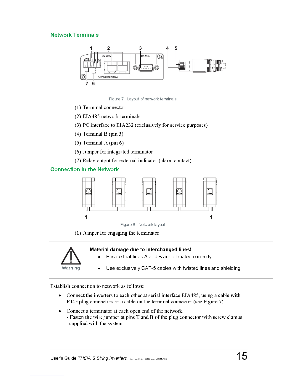
Network Terminals
Figure 7 Layout of network terminals
(1) Terminal connector
(2) EIA485 network terminals
(3) PC interface to EIA232 (exclusively for service purposes)
(4) Terminal B (pin 3)
(5) Terminal A (pin 6)
(6) Jumper for integrated terminator
(7) Relay output for external indicator (alarm contact)
Connection in the Network
Figure 8 Network layout
(1) Jumper for engaging the terminator
Establish connection to network as follows:
•Connect the inverters to each other at serial interface EIA485, using a cable with
RJ45 plug connectors or a cable on the terminal connector (see Figure 7)
•Connect a terminator at each open end of the network.
- Fasten the wire jumper at pins T and B of the plug connector with screw clamps
supplied with the system

16 User’s Guide THEIA S String Inverters 357100.013, Issue 2.0, 2010 Aug
Alarm Contact
•Connect any external indicator device to the potential-free contact.
- When an error is detected, the contact is closed and activates the indicator device
(optical or acoustic warning)
- Setting: see menu Settings →function Alarm contact
•Only use safety extra low voltage (SELV) of max. 24 V as supply voltage
User’s Guide THEIA S String Inverters
357100.013, Issue 2.0, 2010 Aug
17
5.Startup
Note:
Independent of demand, the inverter activates the fan as soon as power input is started (e.g. every morning). When
feeding in, the inverter activates the fan as required.
During the startup, several basic settings such as language selection, date and time settings
are set.
If several inverters are installed which are networked via the EIA485 interface, the startup
can be carried out at any one of the installed inverters (master programming). This inverter
transmits the configuration settings to all other inverters in the network. Every inverter is
automatically assigned a number at its initial startup. The free allocation of this number is
possible in a further step.
The inverters that are not used for input entries display other screen contents depending on
the menu. If no entry is possible, the inverter shows the start screen.
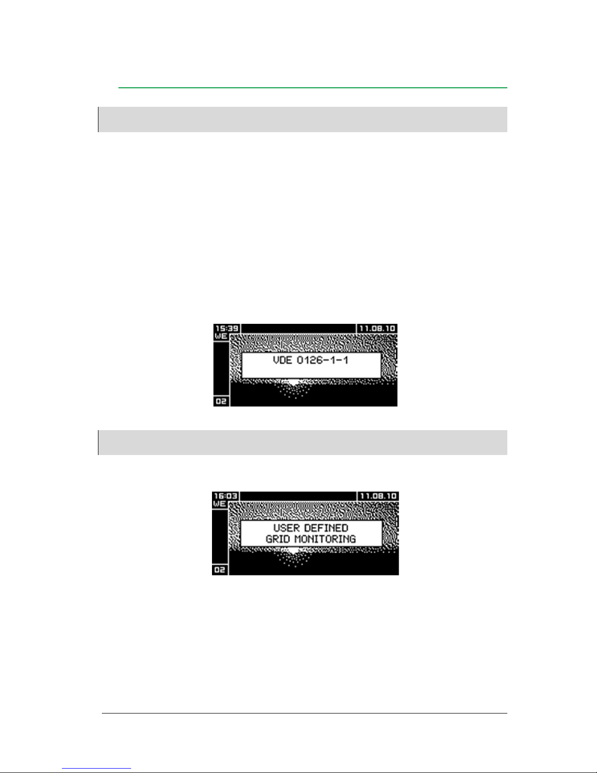
Start screen
All inverters that are not operated during the configuration will show the blocking screen.
Note:
If parameters of the inverter have been adapted to special requirements of the energy supplier, this is indicated on
the start screen.
After changing parameters, the inverter shows the following screen:
18 User’s Guide THEIA S String Inverters
357100.013, Issue 2.0, 2010 Aug
Initial Startup of a Single Inverter
•Switch on the main power supply (fuse)
For inverters with DC disconnector:
•Set switch knob to ‘1’
The inverter is supplied with power. Configuration through the following dialogs.
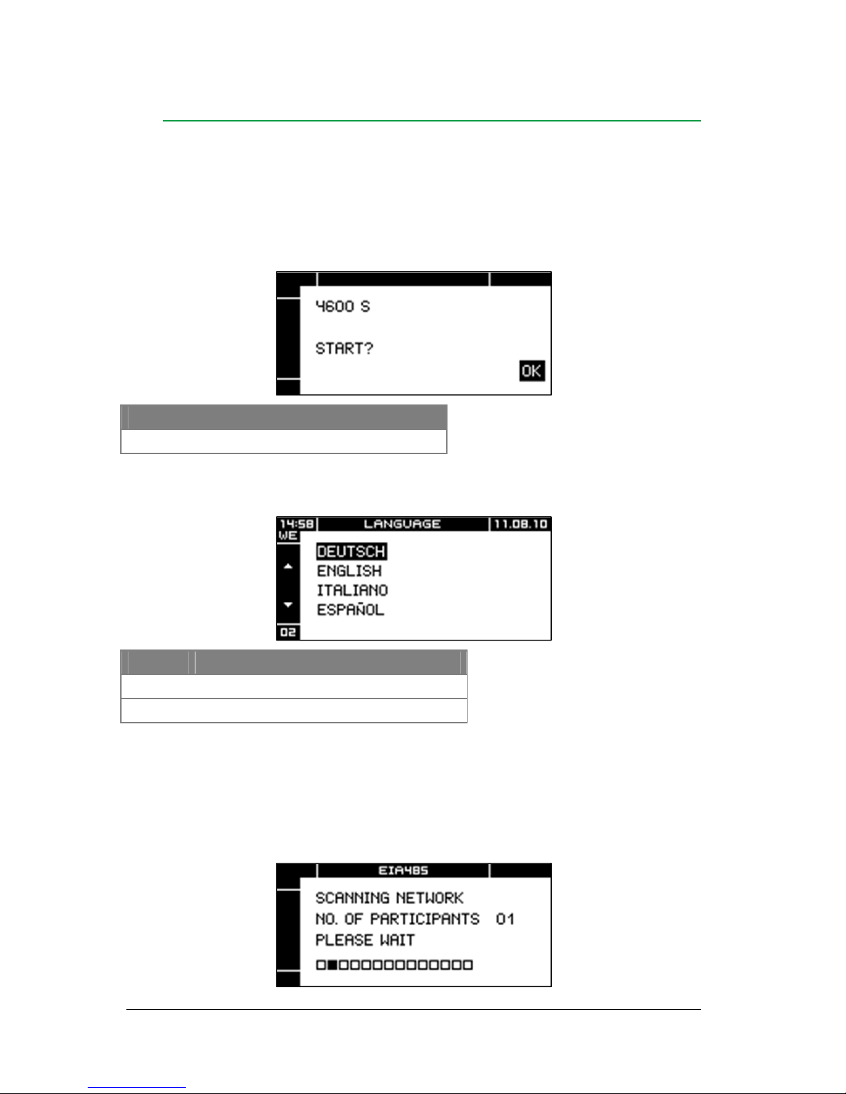
Start initial startup
Key Function
OK Start configuration process with this inverter
Language selection
Key Function
Select language
OK Accept selected language
After the configuration process has been started:
- The inverter scans the network connected by the EIA485-Bus for other inverters.
- All other inverters connected to the network are blocked.
EIA485 bus
As long as the network scan (Scanning Network) is still in process, the display shows the
following screen:
User’s Guide THEIA S String Inverters
357100.013, Issue 2.0, 2010 Aug
19
When the network scan is completed, the display shows the number of detected bus
participants. In case of a single inverter, the display shows 01.
Note:
The network scan can only recognize more than 1 inverter if the inverters are correctly networked via the EIA 485
interface.
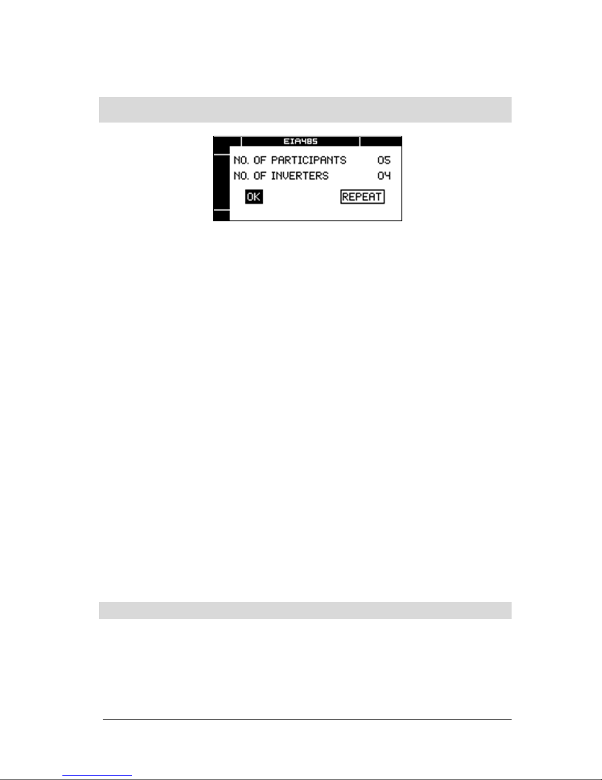
If the number of detected bus participants (e.g. inverters, data loggers, etc.) does not agree
with the installation:
•Select REPEAT
•Press OK key
•Check connections (EIA485 interfaces) if required
If the number of detected bus participants is in agreement with the installation:
•Select OK
•Press OK key
In case of a single inverter:
—Screen Date appears
In case of several networked inverters:
—Screen Inverter numbering appears
Inverter numbering
It is possible to network several inverters via the EIA485 interface. Inverter numbers are
allocated automatically during the network scan. The inverter number is displayed in the
lower left corner of the screen.
For a clearer overview, the inverters can be re-numbered for specific requirements. For
instance, the inverter number can be defined according to the installation sequence.
Example: With three inverters installed, the left one can be allocated the no. 1, the middle
one can be no. 2 and the right-hand one no. 3.
Note:
The following screen is not displayed if only one inverter is configured.
20 User’s Guide THEIA S String Inverters
357100.013, Issue 2.0, 2010 Aug
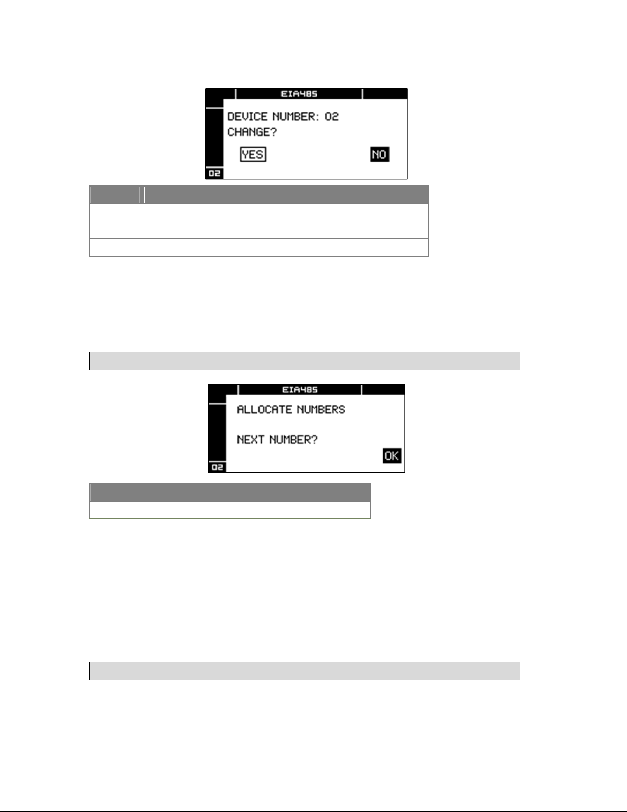
Screen Inverter numbering:
Key Function
YES = Allocate user-defined number to inverter
NO = Accept inverter number unchanged
OK Confirm selection
If NO was selected:
—The inverter adopts the displayed number und switches to the Settings Date screen
If YES was selected:
—The display shows the following screen
Note:
The following screen is not displayed if only one inverter is configured:
After OK was selected:
•Allocate numbers to inverters in the required sequence
— The inverter adopts the next available number
— The display shows the following screen:
Example:
As soon as the OK key was pressed at the first inverter, this inverter is allocated no. 1,
which is shown on the display. When the OK key was pressed at the second inverter, this
inverter is allocated no. 2, etc…
Note:
The following screen is not displayed if only one inverter is started up.
Key Function
OK The inverter adopts the next available number
Table of contents
Other Eltek Valere Inverter manuals


Popular Inverter manuals by other brands


Mastervolt
Mastervolt Sunmaster XS4300 User and installation manual

Sungrow
Sungrow SG60KTL Quick installation quide

Renogy
Renogy PCL Series manual
 instruction manual")
Hitachi
Hitachi SJ-PB(T) instruction manual

Solectria Renewables
Solectria Renewables SGI 500 Installation and operation manual

Amane Studio
Amane Studio IP8E manual


