Eltek Chameleon Stand-alone User manual
Quick Installation Guide
Installation and Commissioning
Power Supply Module, 48 VDC, 650W, HE, IP65
Low Power Outdoor Applications
Chameleon Stand-alone
Introduction
Warnings..................................................................................................................., page 3
Tools & Torque Recommendations....................................................................., page 3
Recommended External AC Fuses......................................................................, page 3
Overview..................................................................................................................., page 4
Block Diagram Chameleon Stand-alone Power Supply Module........................... , page 4
Dimensions Chameleon Stand-alone Module .......................................................... , page 4
Mechanical Installation
Fastening the Chameleon Module to a Surface or Pole ................................, page 5
Option 1: Surface Mounting ~ Prepare the Surface ............................................... , page 5
Option 1: Surface Mounting ~ Fasten the Chameleon Module............................ , page 6
Option 2: Pole Mounting ~ Fasten Half Pole Clamps to the Module................... , page 6
Option 2: Pole Mounting ~ Fasten the Chameleon Module to the Pole............. , page 7
Electrical Installation
Location of Terminals & Cable Management ..................................................., page 8
Cable Management........................................................................................................ , page 8
Pinout ~ Panel Mount Connectors........................................................................... , page 10
Location of Terminals ~ Cable Connectors............................................................ , page 10
Connections.......................................................................................................... , page 11
Switch OFF External Fuses ........................................................................................ , page 11
Connect the AC Input Cable...................................................................................... , page 12
Connect the DC Output Cable.................................................................................. , page 13
Start-Up
Check Lists ~ Pullout
Commissioning Procedure
356849.103

2 Quick Installation Guide • Chameleon 48V, 650W, HE, IP65, Stand-alone Module
356849.103, 2v1-2015-08
!
!
!
!
s
ss
Power Supply Systems
The product warranty becomes invalid if the following safety precautions are not followed during handling,
installation, commissioning and general use/operation of Eltek power supply systems.
SAFETY and ENVIRONMENTAL PRECAUTIONS
General Precautions
Environmental Precautions
Precautions during Installation
CAUTION: Even though the product incorporates protection circuitry and other safeguards, it can be damaged, perform poorly or
have a reduced lifetime if it is exposed to incorrect treatment during transport, installation or service. Always handle the equip-
ment using proper lifting techniques, do not roll, climb or drill hole in the cabinets or enclosures.
CAUTION: Read the user documentation carefully before installing and using the equipment, as installation and operation is to
be performed as described in it. Always tighten screws and bolts with the torque values recommended in the documentation. For
safety reasons, the commissioning and configuration of the equipment is only to be performed by Eltek’s personnel or by author-
ized and qualified persons.
CAUTION: This product is tested and verified according to international safety, environmental and EMC standards. Any non-Eltek
equipment installed into this product after delivery might influence the performance and could infringe the original approvals. The
installer is responsible for ensuring that the environmental properties of this product/ system do not deteriorate during installa-
tion, and that it is performed in accordance with applying regulations.
Installations in USA and Canada must comply with NEC/CEC requirements.
CAUTION: Before you start the electrical installation, you must always disconnect all external supply fuses, as well as internal
battery and load fuses/ breakers, if any.
CAUTION: To avoid damage the equipment, keep objects clear of system ventilation inlets, outlets and system fans, if any, ensur-
ing the airflow through the units is not obstructed, and that the fans rotate freely. Use caution with power modules, as they can
reach extreme temperatures under load and normal operation.
WARNING: The installer/user is responsible for ensuring that the power system is not damaged by current surges, over-voltages,
etc. caused by external transients, lightning, electrostatic discharge, etc. To avoid damage and obtain the expected system reli-
ability, it is mandatory to always install SPDs in Eltek’s power supply systems. Follow the instructions given in “Guidelines for
Lightning and Surge Protection”, doc. 2024623.
WARNING: The electronics in the power supply system are designed for indoor, clean environment. When installed in outdoor
enclosures — using heat sinks or closed loop heat management systems — it is important to maintain the equipment closed and
tight during operation, to avoid external air entering the enclosure. Also, when using open loop heat management systems, it is
important to replace the filters on a regular basis. Indoor installations in dusty or humid areas require appropriate air filtering of
the room, or filtering of the air entering the power system. Follow the instructions given in “Generic Guidelines Environmental
Protection.”, doc. 2038879
WARNING: Opening the equipment may cause terminal injury — even if the mains AC supply is disconnected. Hazardous voltages
may be present inside, as large capacitors may still be charged.
WARNING: For safety reasons (high leakage current / high touch current) you must always connect the AC earth wire (PE) to the
terminals, before you connect the AC input cable(s).
The batteries, if any, represent a major energy hazard. To avoid short-circuit of battery poles, you must always remove metallic
objects — uninsulated tools, rings, watches, etc. — from the vicinity of the batteries.
Device
Hazard
Qualified
Personnel
EMC, NEC/CEC
Regard
Device
Hazard
Electric
Shock
Electric
Shock
Ventilated
Hot Surface
Current Surge
Protection
Humidity & Dust
Protection
G1
I1
I2
I3
E1
E2
E3
G2
I4
356800.183, 3v5 (-I5)
PZ2
W
Flat
(2.5 mm)
T-PZ2
T-IW
Tools
T-F
Torque
Quick Installation Guide • Chameleon 48V, 650W, HE, IP65, Stand-alone Module 3
356849.103, 2v1-2015-08
Introduction
•••
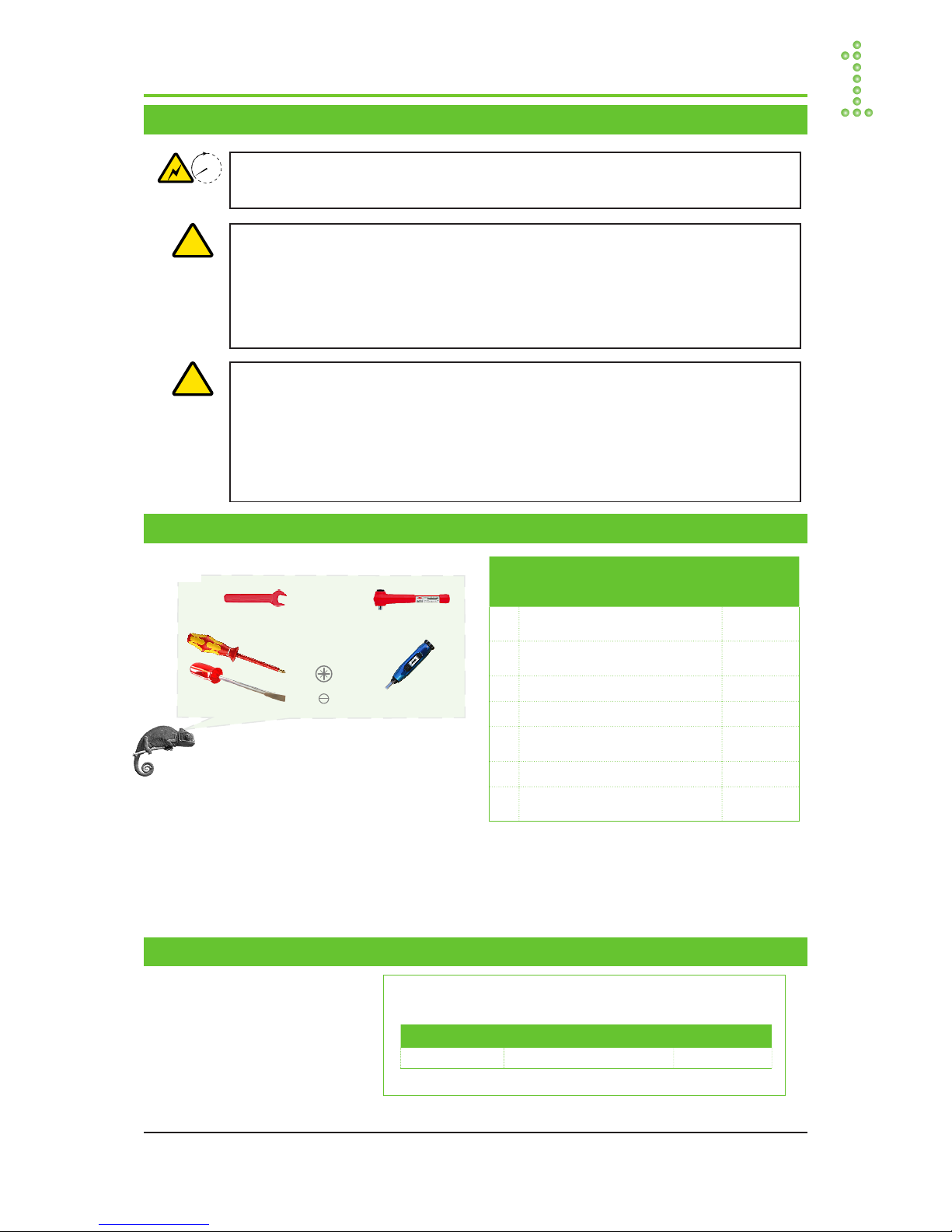
Warnings
Tools & Torque Recommendations
Table 1. Torque recommendations
Recommended External AC Fuses
Table 2. Recommended external AC fuses
NOTICE:
This guide describes the modules:
- Part 241125.105, Chameleon Module 48V, 650W, HE, IP65
- Part 241125.155, Chameleon Module 48V, 650W, HE, IP65, 200ms
- Part 241125.185, Chameleon Module 48V, 650W, HE, IP65, UI
For technical specifications and functionality description, refer to the following:
- 241125.1XX.DS3, Datasheet Chameleon 48V, 650W, HE, Rectifiers
- For generic power system functionality, refer to CWUI Online Help
!
WARNING:
Hazardous voltages may be present inside the Chameleon module, Part # 241125.155, as long as 10
minutes after it is switched OFF (discharge time)
Electric Shock
10min.
Recommended External AC Fuses
Chameleon 48V, 650W, HE Stand-alone Modules
Rectifier: Chameleon 48/650 HE
AC Type Fuse Type
230VAC 1 phase 20A C-char or 16A D-char Th/Mag
(Doc 2126770, 1v0)
Torque Recommendations
Type & Size Torque (Nm)
T1 M5 screws (2x)
(fastening module to clamps)
5.0
T2 M5 bolts (4x)
(fastening half pole clamps)
3.0**
T3 AC Mains Input Terminals (4x) 0.3
T4 DC Output Terminals (7x) 0.4
T5 Coupling rings on the cable con-
nectors’ inserts
1.5
T6 Cable connectors’ sleeves 0.5
T7 Cable connectors’ pressing screws.
See Table 3 on page 9
Note: General tolerance: ±10%
** T2’s exact tightening moment may vary a little depending
on the type of half pole clamps used and the diameter of
the pole
WARNING:
– If used as PERMANENTLY CONNECTED, a readily accessible disconnect device shall be incorporated
external to the equipment
– If used as PLUGGABLE EQUIPMENT, the socket-outlet shall be installed near the equipment and shall
be easily accessible.
– Maximum operational ambient temperature of this equipment is 60°C or, if installed in a RESTRICTED
ACCESS LOCATION, 70°C
!

CAN bus
AC Fuses,
external
AC Input
(230V 1x phase)
DC Output
(48V)
(Load)
Telecom &
Industrial
Equipment
Chameleon
48V, 650W, HE
Stand-alone Module
Alarm
Relay
C-NO
Chameleon Stand-alone Module
Part 241125.105 (2.8Kg, H=320.6)
Part 241125.185 (2.8Kg, H=320.6)
Part 241125.155 (3.6Kg, H=450.0)
W = 96.0
H = 320.6 or 450.0
D = 106.6
Panel Mount
Connectors
(Ref. Doc# 2175763, v1.0)
All dimentions in mm (not in scale)
4 Quick Installation Guide • Chameleon 48V, 650W, HE, IP65, Stand-alone Module
356849.103, 2v1-2015-08
Introduction •••
Overview
Block Diagram Chameleon Stand-alone Power Supply Module
Dimensions Chameleon Stand-alone Module

1
All dimentions in mm (not in scale)
Get ready suitable acid proof (A4) screws or bolts (2x)
2Mark the center line,
then drill 2 suitable holes in the wall
D
Part 241125.105 (D=302.5)
Part 241125.185 (D=302.5)
Part 241125.155 (D=432.4)
Quick Installation Guide • Chameleon 48V, 650W, HE, IP65, Stand-alone Module 5
356849.103, 2v1-2015-08
Mechanical Installation
Fastening the Chameleon Module to a Surface or Pole
Option 1: Surface Mounting ~ Prepare the Surface
NOTICE:
Use acid proof (A4) screws or bolts (not included) suitable for
the mounting surface and outdoor environment, to fasten the
Chameleon module to the wall or support surface (e.g. wall
plugs, expansion bolts, molly bolts, etc.)
Or use suitable half pole clamps (included in Pole Mount Kit,
Part 241125.910), if the module is to be pole mounted
!
Suitable Screws or Bolts
Halv Pole Clamps
40-95 mm Ø
Halv Pole Clamps
90-135 mm Ø
Pole Mount Kit
Part 241125.910
CAUTION:
The wall or support surface or pole must be capable of supporting the equip-
ment: 2.8 Kg or 3.6Kg, ±10%, depending on the Chameleon Stand-alone Module
!
WARNING:
Never mount the Chameleon Stand-alone Module in the vicinity of heaters or
above hot sources
!
•••
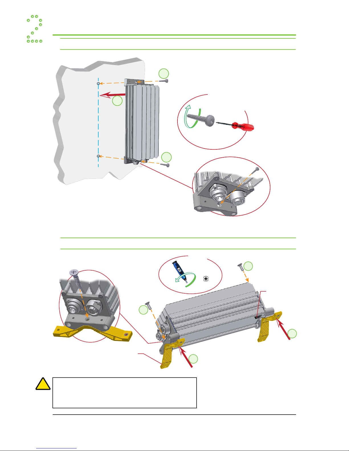
1
2
3
M5 (2x)
Chameleon
Stand-alone Module
Half Pole Clamp
Pressure
Equalization Vent
4
T1
CW
T-PZ2
1
2
3
(2x)
Suitable acid proof (A4)
Screw or Bolt
CW
Chameleon
Stand-alone Module
6 Quick Installation Guide • Chameleon 48V, 650W, HE, IP65, Stand-alone Module
356849.103, 2v1-2015-08
Mechanical Installation
Option 1: Surface Mounting ~ Fasten the Chameleon Module
•••
Option 2: Pole Mounting ~ Fasten Half Pole Clamps to the Module
WARNING:
Do not open, close or change the Pressure Equalization Vent, which
provides pressure equalization and condensation reduction, and re-
sists liquid immersion, dust and dirt while allowing the product to
breath during changing environmental conditions
!
Device
Hazard

1
2
3
3
3
3
3
3
M5 (4x)
Chameleon
Stand-alone Module
Pole
Half Pole Clamp
Half Pole Clamp
4
T2
CW
5
5
5
5
5
5
5
5
5
T-IW
Chameleon Stand-alone Module
(Top View)
Chameleon Stand-alone Module
(Top View)
Half Pole Clamp
Pole B
B
A
A
A=B
OK NOT OK
A≠B
6
7
Quick Installation Guide • Chameleon 48V, 650W, HE, IP65, Stand-alone Module 7
356849.103, 2v1-2015-08
Mechanical Installation
•••
Option 2: Pole Mounting ~ Fasten the Chameleon Module to the Pole
Optionally, you can cut the clamp bolts to suitable lengths after fastening them
(steps 6 and 7).
WARNING:
Both bolts tightening a half pole
clamp pair must be screwed almost at
the same time and the same length,
maintaining the half pole clamps par-
alleled while fastening
!
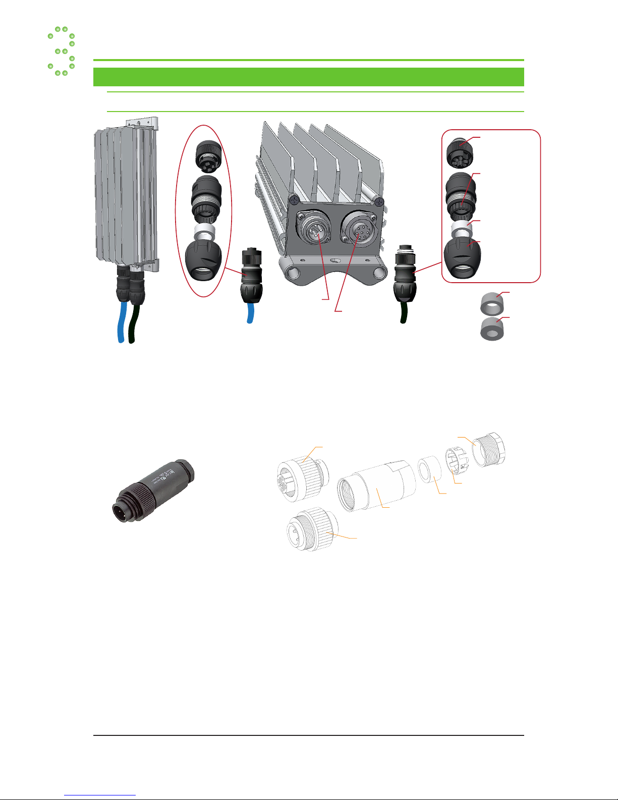
Chameleon Stand-alone Module
Cable
Connector,
male
F (Part 343667)
Cable
Connector,
female
A (Part 343665)
Panel Mount
Connector,
male
Panel Mount
Connector,
female
Insert, male
with Coupling Ring
Sleeve
with Pinch Ring
Seal Ring, SR1
Seal
Ring, SR1
Seal
Ring, SR2
Pressing Screw
Insert, male
with Coupling Ring
Sleeve
Seal Ring
Pressing Screw
Pinch Ring
Insert, female
with Coupling Ring
8 Quick Installation Guide • Chameleon 48V, 650W, HE, IP65, Stand-alone Module
356849.103, 2v1-2015-08
•••
Electrical Installation
Location of Terminals & Cable Management
Cable Management
Cable connectors A and F shown above are suitable for a wider cable outer diam-
eter range. Cable connectors B-E and G-J are shown below. Refer to “Table 3. Selec-
tion of Cable Connectors” on page 9
Power is OFF!

PULLOUT
Check Lists Pullout
Pull out the pages with the gray outer band,
and use them as check lists
Form 186-gb-2v1-C01
COMMISSIONING PROCEDURE
System Data Chameleon Module
Supplier’s Order No.:
Chameleon Stand-alone Module, type:
Article No.:
Site, name:
Serial No.:
Software, version No.:
AC Input Voltage, measured:
Commissioning carried out by, name:
Pre-Start Check Power is OFF!
CHECK FOLLOWING:
OK
1. Chameleon Stand-alone installation is completed;
All cabling is securely terminated
2. Site specific parameters are known
3. All external load MCBs/ fuses are switched OFF
4. All external AC mains MCBs/ fuses are switched OFF; AC supply is OFF
Hazardous voltages are present inside Chameleon module, Part # 241125.155, as long as 10 min. after switch OFF
5. Both cable connectors are correct type
The correct type must be suitable for the cables’ outer diameter. Refer to the QI guide, doc. 356849.103
6. AC input cable and AC earth wire (PE) are terminated in the input cable connector
7. DC output cable is terminated in the output cable connector
8. The input and the output cable connectors are plugged in the Chameleon module
Start-up, No-Load Measurements Power is ON!
CARRY OUT FOLLOWING:
OK
1. Unplug the Output Cable Connector from the module
2. Switch ON the system (external AC MCBs/fuses ON)
3. DC output voltage; Measure at the module’s output panel mount connector, pin1 & 2
Verify correct output voltage (-43V to 58V, ±1V)
4. Alarm relay test;
Verify that the alarm contacts (max. 30VDC, 2A), on the module’s output panel mount connector, work OK
Measure resistance between pin 5 & 6 (AL C —AL NC)
R> 100MΩ → normal condition, coil energized
Unplug the AC Input Cable Connector
R≈ 0Ω → alarm condition, coil de-energized
Plug again the AC Input Cable Connector
5. Plug again the Output Cable Connector to the module
6. Switch ON external load MCBs/ fuses,
If possible, verify that the load is supplied with correct voltage (-43V to 58V, ±1V)
Approval
Responsible of commissioning, sign.:
Date:
Approved by customer, sign.:
1(1)
Device
Hazard
!
I
II
Device
Hazard
!
Electric Shock
10 min

PULLOUT
PULLOUT

PULLOUT
Check Lists Pullout
Pull out the pages with the gray outer band,
and use them as check lists
Circular
Cross Section
Quick Installation Guide • Chameleon 48V, 650W, HE, IP65, Stand-alone Module 9
356849.103, 2v1-2015-08
Electrical Installation
•••
Select the cable connector type that corresponds to your cable outer diameter,
±0.2mm
Table 3. Selection of Cable Connectors
Cable Connectors Selection Table
Cable Type Cable Connector Type
Function Outer Diameter Connector Type Eltek’s Part No. Binder’s Part Number Pressing Screw’s Torque
Input Cable 12—17 mm
7.0—13 mm
A Input Connector (SR1)
Input Connector (SR2)
343665 99-4222-300-04 (3+PE) 1.6—2.0 Nm
0.8—1.4 Nm
Input Cable 6.0—9.5 mm B Input Connector 334321 99-4222-00-04 (3+PE) 0.8—1.0 Nm
Input Cable 8—10 mm C Input Connector 334322 99-4222-110-04 (3+PE) 1.0—1.4 Nm
Input Cable 10—12 mm D Input Connector 334323 99-4222-14-04 (3+PE) 1.0—1.4 Nm
Input Cable 12—14 mm E Input Connector 314804 99-4222-160-04 (3+PE) 1.0—1.4 Nm
Output Cable 12—17 mm
7.0—13 mm
F Output Connector (SR1)
Output Connector (SR2)
343667 99-4217-300-07 (6+PE) 1.6—2.0 Nm
0.8—1.4 Nm
Output Cable 6—8 mm G Output Connector 334328 99-4217-00-07 (6+PE) 0.8—1.0 Nm
Output Cable 8—10 mm H Output Connector 334329 99-4217-110-07 (6+PE) 1.0—1.4 Nm
Output Cable 10—12 mm I Output Connector 334330 99-4217-14-07 (6+PE) 1.0—1.4 Nm
Output Cable 12—14 mm J Output Connector 314805 99-4217-160-07 (6+PE) 1.0—1.4 Nm
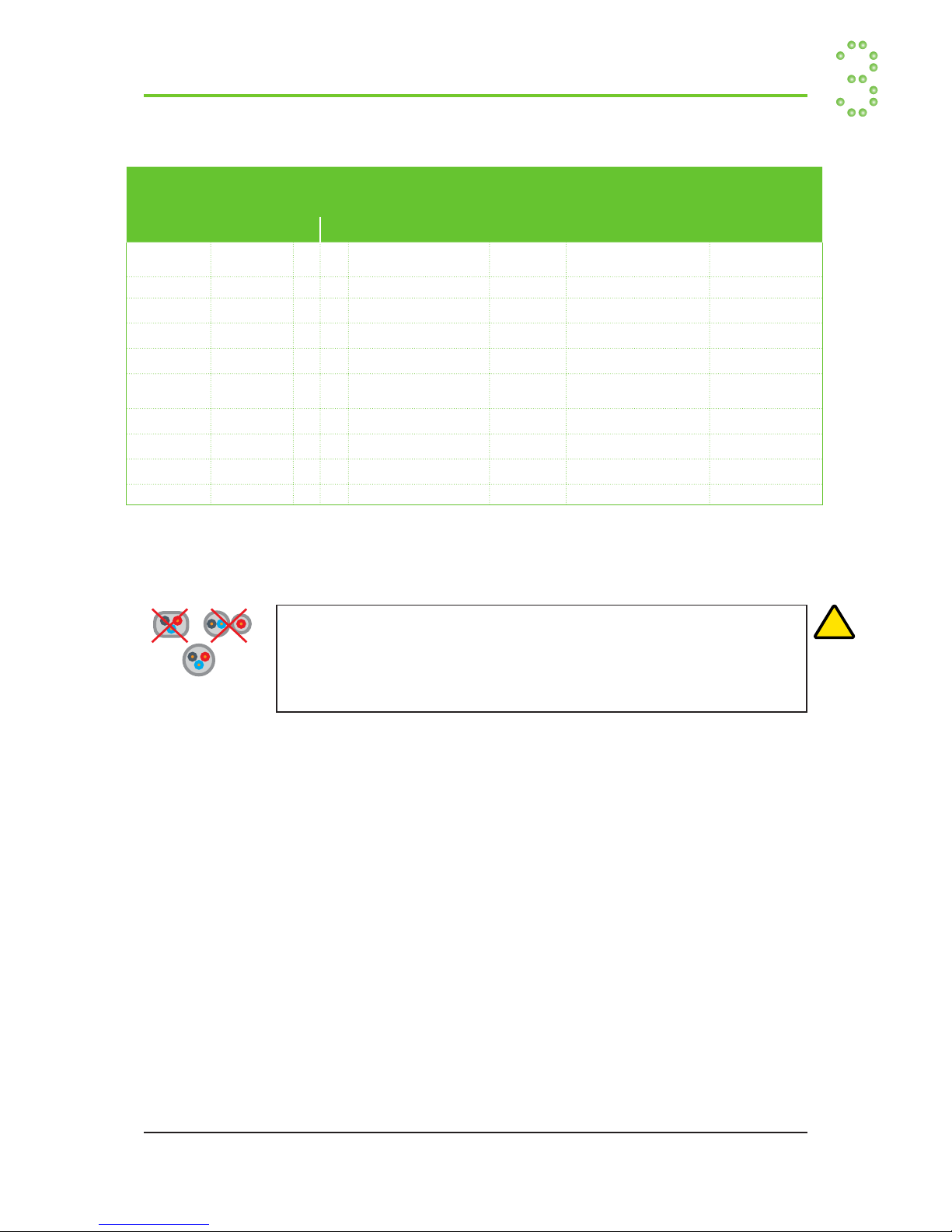
WARNING:
— To avoid corrosion of the screw terminals and field failures not covered by the warranty, al-
ways use cables with circular cross section, and cable connectors and seal rings suitable for
the cable’s outer diameter
— The cable connectors in Table 3 on page 9 are suitable for PUR and PVC type cables with
circular cable cross section
!
Device
Hazard

Contacts
shown with
de-energized
coil (Alarm
condition)
1
(Not
Connected)
1
+
0VDC
2
L1/N
2
—
-48VDC
3
CAN H
4
CAN L
5
AL-C
6
AL-NO
3
L2
AC Mains
Input
Terminals
DC Load
Output
Terminals
Flat 2.5mm
T4
Flat 2.5mm
T3
Chameleon Stand-alone Module
Cable
Connector,
male
F (Part 343667)
Cable
Connector,
female
A (Part 343665)
Insert, male
with Coupling Ring
Sleeve
with Pinch Ring
Seal Ring
Pressing Screw
Seal
Ring, SR1
Seal
Ring, SR2
Contacts
shown with
de-energized
coil (Alarm
condition)
1
+
0VDC
2
L1/N
2
—
-48VDC
(not connected)
1
(not connected)
3
CAN H
4
CAN L
5
AL-C
6
AL-NO
3
L2
PE
Pinout
Panel Mount
Input Connector
Pinout
Panel Mount
Output Connector
Chameleon Stand-alone Module
10 Quick Installation Guide • Chameleon 48V, 650W, HE, IP65, Stand-alone Module
356849.103, 2v1-2015-08
•••
Electrical Installation
Pinout ~ Panel Mount Connectors
Location of Terminals ~ Cable Connectors
For torque reference T3, T4, read “Tools & Torque Recommendations” on page 3

2
1Switch OFF external AC Mains MCBs/Fuses
Switch OFF external Load MCBs/Fuses
Quick Installation Guide • Chameleon 48V, 650W, HE, IP65, Stand-alone Module 11
356849.103, 2v1-2015-08
Electrical Installation
•••
Connections
Switch OFF External Fuses
Power is OFF!
WARNING:
The other ends of the AC input and DC output cables must be terminated in a protected box or plug of at least IP65
rating, or in an indoor environment
!
Device
Hazard
For installations in USA and Canada only!
The installation has to comply with the
NEC/CEC requirements
A1
WARNING:
For outdoor applications where the product may be subject
to transient overvoltages exceeding those for Overvoltage
Category II, an AC Overvoltage Protection Device (OVP)
complying with IEC 61643-series must be installed on the
AC supply. This device will reduce the overvoltages to levels
corresponding to Overvoltage Category II
Current Surge
Protection
U5 CAUTION:
Suitable for connection to IT networks
U2a
!
WARNING:
Hazardous voltages may be present inside the Chameleon module, Part # 241125.155, as long as 10
minutes after it is switched OFF (discharge time)
Electric Shock
10min.

Tin wires (3x)
Cable
Connector,
female
A (Part 343665)
Cable
Connector,
female
A (Part 343665)
1
CCW
CCW
2
3
5
6
7mm
AC Mains
Cable
4
25mm
AC Mains
Cable
7
8
9
10
1112
Connect
AC Mains cable
Max 0.52.5mm (2014 AWG)
AC Mains
Cable
AC Mains
Cable
1
2
L1/N
3
L2
AC Mains
Input Terminals
CW
CW CW
13
14
15
Chameleon Stand-alone Module
16
17
T5
T6
T7
12 Quick Installation Guide • Chameleon 48V, 650W, HE, IP65, Stand-alone Module
356849.103, 2v1-2015-08
•••
Electrical Installation
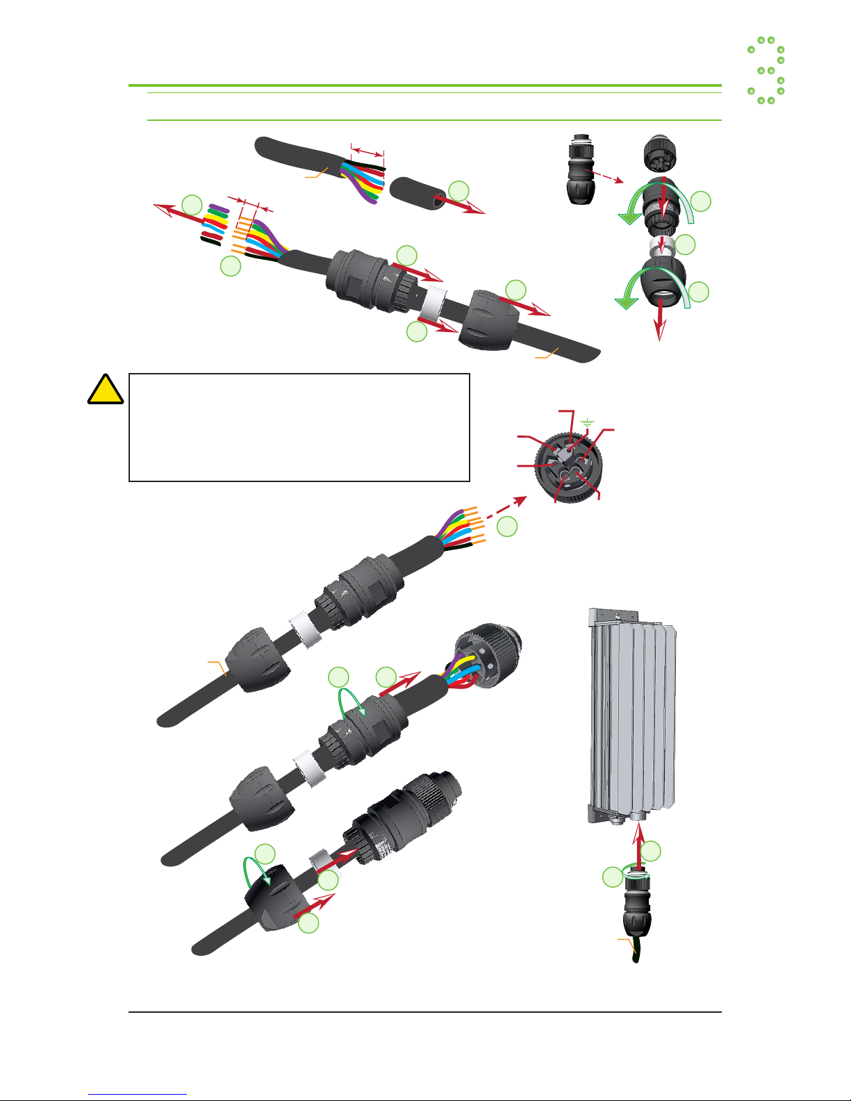
Connect the AC Input Cable
For torque reference T5-T7, read “Tools & Torque Recommendations” on page 3
Use similar connection procedure for input cable connectors B through E
CAUTION:
The rectifier incorporates a Mains fuse in
each line. Double Pole / Neutral Fusing
N
U1
1
2
3
5
6
7
8
9
10
1112
Connect
DC Output cable
Max 0.41.5mm (2216 AWG)
DC Output
Cable
DC Output
Cable
CW
CW CW
13
14
15
Chameleon Stand-alone Module
16
17
Cable
Connector,
male
F (Part 343667)
Cable
Connector,
male
F (Part 343667)
CCW
CCW
25mm
DC Output
Cable 4
Tin wires (7x)
7mm
DC Output
Cable
1
+0V
2
−48V
3
CAN H
4
CAN L
5
AL-C
6
AL-NO
DC Load
Output Terminals
T5
T6
T7
Quick Installation Guide • Chameleon 48V, 650W, HE, IP65, Stand-alone Module 13
356849.103, 2v1-2015-08
Electrical Installation
•••
Connect the DC Output Cable
For torque reference T5-T7, read “Tools & Torque Recommendations” on page 3
WARNING:
— Careful! Use correct polarity!
— The DC Load’s wire cross section must be 1.5mm (pin 1 & 2)
— Relay contacts shown with de-energized coil (Alarm condition)
— The Earth terminal in the output panel mount connector is not
connected inside the module
!
Use similar connection procedure for output cable connectors G through J

14 Quick Installation Guide • Chameleon 48V, 650W, HE, IP65, Stand-alone Module
356849.103, 2v1-2015-08
•••
Electrical Installation

Quick Installation Guide • Chameleon 48V, 650W, HE, IP65, Stand-alone Module 15
356849.103, 2v1-2015-08
Start-Up
•••
Refer to the steps in the pull-out form “Commissioning Procedure”

This product is CE marked and complies
with all current requirements for relevant
standards and directives.
www.eltek.com
Headquarters: Eltek
Visitor address: Gråterudveien 8, 3036 Drammen, Norway
Phone: +47 32 20 32 00 Fax: +47 32 20 32 10
356849.103, 2v1-2015-08, Published 2015-11-25
Table of contents
Other Eltek Power Supply manuals


