ELTEX KNH35 User manual

Operating Instructions
KNH35 High Voltage Generator
BA-en-3031-2004
F00038y

2BA-en-3031-2004_KNH35

BA-en-3031-2004_KNH35 3
List of Contents
1 Outline of Appliance . . . . . . . . . . . . . . . . . . . . . . . . . . . . . . . . . . . 6
2 Safety . . . . . . . . . . . . . . . . . . . . . . . . . . . . . . . . . . . . . . . . . . . . . . . 7
2.1 Identification of risks and hazards . . . . . . . . . . . . . . . . . . . . . . . . . . 7
2.2 Contact protection . . . . . . . . . . . . . . . . . . . . . . . . . . . . . . . . . . . . . . 7
2.3 Technical advance . . . . . . . . . . . . . . . . . . . . . . . . . . . . . . . . . . . . . . 7
2.4 Proper Use . . . . . . . . . . . . . . . . . . . . . . . . . . . . . . . . . . . . . . . . . . . 7
2.5 Work and operational safety . . . . . . . . . . . . . . . . . . . . . . . . . . . . . . 8
3 Installation . . . . . . . . . . . . . . . . . . . . . . . . . . . . . . . . . . . . . . . . . . 11
3.1 Assembly of the high voltage generator . . . . . . . . . . . . . . . . . . . . 11
3.2 Ground connection . . . . . . . . . . . . . . . . . . . . . . . . . . . . . . . . . . . . . 12
3.3 Installation of the high voltage cables . . . . . . . . . . . . . . . . . . . . . . 12
3.4 Charging bars suitable for connection . . . . . . . . . . . . . . . . . . . . . . 13
3.5 Connecting the high voltage cable to the high voltage generator
and to the distribution box . . . . . . . . . . . . . . . . . . . . . . . . . . . . . . . 14
3.6 Disconnecting the high voltage cable . . . . . . . . . . . . . . . . . . . . . . 15
3.7 Connecting the supply voltage . . . . . . . . . . . . . . . . . . . . . . . . . . . 16
3.7.1 Variant with connecting terminals. . . . . . . . . . . . . . . . . . . . . . . . . . 16
3.7.2 Variant with connecting plugs. . . . . . . . . . . . . . . . . . . . . . . . . . . . . 17
3.8 Analog interface . . . . . . . . . . . . . . . . . . . . . . . . . . . . . . . . . . . . . . . 18
3.8.1 Variant with connecting terminals. . . . . . . . . . . . . . . . . . . . . . . . . . 18
3.8.2 Variant with connecting plugs. . . . . . . . . . . . . . . . . . . . . . . . . . . . . 20
3.9 Laying the cable shield of the interface cable . . . . . . . . . . . . . . . . 21
4 Operation . . . . . . . . . . . . . . . . . . . . . . . . . . . . . . . . . . . . . . . . . . . 23
4.1 Start-up . . . . . . . . . . . . . . . . . . . . . . . . . . . . . . . . . . . . . . . . . . . . . 23
4.2 Menu system . . . . . . . . . . . . . . . . . . . . . . . . . . . . . . . . . . . . . . . . . 24
4.3 Overview of functions with options and factory settings . . . . . . . . 26
4.4 Selecting the setpoint . . . . . . . . . . . . . . . . . . . . . . . . . . . . . . . . . . 28
4.5 Selectiong the operating parameters (Password protecion). . . . . . 28
4.6 Specific operating parameters for the high voltage output . . . . . . . 29
4.7 Global operting parameters . . . . . . . . . . . . . . . . . . . . . . . . . . . . . . 34
4.8 Service menu . . . . . . . . . . . . . . . . . . . . . . . . . . . . . . . . . . . . . . . . . 35
5 Maintenance . . . . . . . . . . . . . . . . . . . . . . . . . . . . . . . . . . . . . . . . . 38
5.1 HIgh voltage generator . . . . . . . . . . . . . . . . . . . . . . . . . . . . . . . . . . 38
5.2 Charging bars . . . . . . . . . . . . . . . . . . . . . . . . . . . . . . . . . . . . . . . . . 38
6 Warranty . . . . . . . . . . . . . . . . . . . . . . . . . . . . . . . . . . . . . . . . . . . . 39
7 Troubleshooting . . . . . . . . . . . . . . . . . . . . . . . . . . . . . . . . . . . . . 40
8 Technical specifications . . . . . . . . . . . . . . . . . . . . . . . . . . . . . . . 42

4BA-en-3031-2004_KNH35
9 Dimensions . . . . . . . . . . . . . . . . . . . . . . . . . . . . . . . . . . . . . . . . . .43
10 Spare parts and accessories . . . . . . . . . . . . . . . . . . . . . . . . . . .44
A Annex . . . . . . . . . . . . . . . . . . . . . . . . . . . . . . . . . . . . . . . . . . . . . .45
A.1 Assembly instructions Plug connectors
Analog interface . . . . . . . . . . . . . . . . . . . . . . . . . . . . . . . . . . . . . . .45
Declaration of Conformity . . . . . . . . . . . . . . . . . . . . . . . . . . . . . . . . . .47

BA-en-3031-2004_KNH35 5
Dear customer,
The KNH35 High Voltage Generator is a multi-purpose voltage supply unit
for any high voltage application and for Eltex DC-operated charging bars.
The following bar models are available for connection:
R130A/R131A,
R120/R121A (note voltage limitation acc. to Operating Instructions
R120/R121A),
R23ATR.
Programmable output and monitoring parameters, an outstanding feature
of the KNH35 microprocessor-controlled high voltage generator, allow it to
be adapted to any kind of operating condition. User operation is menu-
assisted; texts and messages appear in plain text on a two-line display.
Also, the monitoring of important functions (high voltage cascade, calibra-
tion short-circuit current, voltage and current limitation) of the KNH35 high
voltage generator provides the ultimate in safety standards.
Please read these instructions carefully before starting the unit. This will
help you prevent personal injuries and damage to property.
Simply give us a call if you have any suggestions, proposals or ideas for
improvements. We greatly appreciate the feedback from the users of our
appliances.

6BA-en-3031-2004_KNH35
1. Outline of Appliance
1 High voltage output 1
2 High voltage output 2
3 Ground terminal
4 Master switch ON/OFF
5 Cable gland: analog interface connection
6 Cable gland: mains voltage connection
7a Front plate with screw-type terminals
7b Front plate with plugs
8 Analog interface
13 System input
Fig. 1:
High Voltage
Generator with
screw-type
terminals
Z-116929y_1
D
Fig. 2:
High Voltage
Generator with
sockets
Z-116929y_3
E

BA-en-3031-2004_KNH35 7
2. Safety
The units have been designed, built and tested using state-of-the-art engi-
neering, and have left the factory in a technically and operationally safe
condition. If used improperly, the units may nevertheless be hazardous to
personnel and may cause injury or damage. Read the operating instruc-
tions carefully and observe the safety instructions.
2.1 Identification of risks and hazards
Possible risks and hazards resulting from the use of the units are referred
to in these operating instructions by the following symbols:
Warning!
This symbol appearing in the operating instructions refers to operations
which, if carried out improperly, may result in serious personal injuries.
Caution!
This symbol appearing in the operating instructions refers to operations
which, if carried out improperly, may result in damage to property.
2.2 Contact protection
The site of installation and/or use of the units is outside the control of
Eltex, contact protection against inadvertent contact of the bars and of live
components by personnel as specified by the employer’s liability insu-
rance association may have to be provided (e.g. DGUV V3 in Germany).
Contact protection devices made of conductive material must be
grounded.
2.3 Technical advance
The manufacturer reserves the right to make changes to the technical
specifications without prior notice in order to adapt the units to state-of-
the-art engineering. Eltex will provide the latest information on any
changes or modifications in the operating instructions on request.
2.4 Proper Use
The KNH35 high voltage generator has been approved as operating volt-
age generator for the appropriate Eltex charging bars. It must be operated
only with the appropriate Eltex bars (see chapter Installation and Assem-
bly for bar models).
If the unit is used in any other high voltage application, the manufacturer´s
warranty covers the safe use in terms of technical safety.
The manufacturers will not assume any liability and warranty if the units
are used improperly or used outside the intended purpose.
Modifications or changes made to the devices are not permitted.
Use only original Eltex spare parts and equipment.

8BA-en-3031-2004_KNH35
2.5 Work and operational safety
Warning!
Carefully observe the following notes and the complete chapter 2 "Safety”,
page 7!
Always observe the rules and regulations applying in your country with
reference to opening electrical appliances.
• Before carrying out repairs, cleaning or maintenance work and before
resetting the unit after malfunctions, switch off the high voltage genera-
tor and disconnect the mains power supply (see chapter 5 "Mainte-
nance”, page 38, chapter 7 "Troubleshooting”, page 40).
• Any work involving the units must be carried out by qualified electri-
cians (see chapter 5 "Maintenance”, page 38, chapter 7 "Troubleshoot-
ing”, page 40).
• Before carrying out any work involving the units, the machine which has
the units fitted must not be in operation (see chapter 3.3 "Installation of
the high voltage cables”, page 12, chapter 3.6 "Disconnecting the high
voltage cable”, page 15, chapter 5 "Maintenance”, page 38, chapter 7
"Troubleshooting”, page 40).
• A permanent grounding connection must be made and checked via the
ground terminal (3, Fig. 1 - Fig. 2) and routed with the shortest possible
distance to the machine frame. The ground cable should have a mini-
mum cross section of 1.5 mm2. A cross section of 2.5 mm2is required
for cable lengths exceeding 0.5 meters. (see chapter 3.2 "Ground con-
nection”, page 12).
• Depending on the parameter setting <Autom. Start>, high voltage may
be applied immediately after activating the supply voltage (see chapter
4.1 "Start-up”, page 23).
• Before switching on the unit, the operator must make sure that
installation and connections have been properly made. If yes, the
supply voltage can be switched on (see chapter 4 "Operation”,
page 23).
• Check the units, the electrical wiring and the hight voltage cable at
regular intervals and before startup for any damage. Any damaged
components must be repaired profesionally or replaced before conti-
nuing to operate the units, or the bar or cable must be disabled.
• Connect or disconnect the high voltage cable / the bars only with the
generator switched off (see chapter 3.5 "Connecting the high voltage
cable to the high voltage generator and to the distribution box”,
page 14).
• The mains cable must be plugged / drawn into the mains inlet socket of
the generator only with the generator switched off (see chapter 3.7.2
"Variant with connecting plugs”, page 17).

BA-en-3031-2004_KNH35 9
• The site of installation must be dry and free of dust, if possible. Air cir-
culation must not be obstructed (see chapter 3.1 "Assembly of the high
voltage generator”, page 11).
• To make sure that no high voltage is applied at the bars when the
machine is not running, the supply voltage to the generator should be
enabled via a machine contact which disables the high voltage when
the machine is at rest (see chapter 3.7 "Connecting the supply voltage”,
page 16).
• When routing the high voltage cable observe all notes in chapter 3.3
"Installation of the high voltage cables”, page 12.
• If the housing cover is removed and the supply voltage is switched on
at the same time, contact protection is no longer effective. Always dis-
connect the power before opening the units (see chapter 3.7 "Connect-
ing the supply voltage”, page 16).
• (see chapter 3.4 "Charging bars suitable for connection”, page 13).
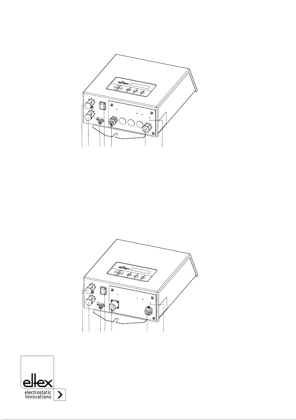
• The high voltage cable must be pushed up to the stop (90 mm) into the
cable inlet! The connecting area of the high voltage cable must be kept
clean (see chapter 3.5 "Connecting the high voltage cable to the high
voltage generator and to the distribution box”, page 14).
• To avoid damaging the generator, make sure that the signals are con-
nected correctly (see chapter 3.8 "Analog interface”, page 18).
• Fusing protection for the fault alarm contact must be provided by the
customer (see chapter 3.8 "Analog interface”, page 18).
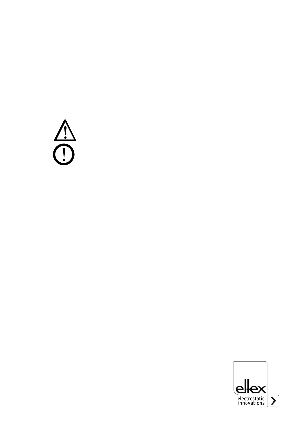
• Shielded cables must be used to wire the analog interface and for all
interface cables; the shield must make contact on both sides (see chap-
ter 3.8 "Analog interface”, page 18, chapter 3.9 "Laying the cable shield
of the interface cable”, page 21, chapter A.1 "Assembly instructions
Plug connectors Analog interface”, page 45).
• In the variant with connecting terminals, the cable shield of the interface
cable must be routed via the EMC cable gland to ground potential (see
chapter 3.9 "Laying the cable shield of the interface cable”, page 21).
• If <YES> has been selected for automatic runup, high voltage is
available immediately after the supply voltage to the generator is
switched on (see chapter 4.6 "Specific operating parameters for the
high voltage output”, page 29).
• Make sure that the units are clean at all times.
Dirt results in malfunctions and in premature wear of the units.
• The IP54 protection class applies only if the lid of the enclosure is
closed and the cable entries are covered.

10 BA-en-3031-2004_KNH35
• The generator must be checked regularly to ensure its proper function-
ing. The connections of the high voltage cables must be free of dirt and
other foreign matter (see chapter 5.1 "High voltage generator”,
page 38).
• When cleaning do not soak the bars and the high voltage cable in sol-
vent and do not damage the emission tips; allow the solvent to evapo-
rate completely before restarting the unit (see chapter 5 "Maintenance”,
page 38).
• The operation of the bars can generate ozone. The ozone concentra-
tion levels developing near the bars depend on many different factors
such as site of installation, bar current and voltage, air circulation, etc.,
and can therefore not be specified in general terms.
If the maximum allowable concentration of ozone must be observed at
the site of installation of the bar, the concentration must be measured
on site.
The AGW value (maximum admissible concentration) serves to assess
the ozone concentration at the workplace. The user must make sure
that the appropriate national AGW value is at no times exceeded, e.g.
in Germany the ozone concentration occurring during the operation of
the system must not exceed the recommended value based on interna-
tional limits of 0.06 ml/m³ (0.12 mg/m³).
•Static on personnel
Static charges on personnel are unlikely if the bars are installed proper-
ly. Personnel must wear conductive footwear.
Please note all national regulations regarding electrostatic charge (e.g.
TRGS 727 in Germany).

BA-en-3031-2004_KNH35 11
3. Installation
3.1 Assembly of the high voltage generator
The unit is designed for wall mounting. Attach the unit using the assembly/
mounting brackets supplied with the unit. When mounting the unit make
sure that the operating elements and the connector terminals remain
accessible and that control of the unit is not impaired.
The site of installation must be dry and free of dust, if possible. Air circula-
tion must not be obstructed.
Fig. 3:
Installation of the
high voltage
generator
Z01034y
405
371
320A>150
245
107
M8
M8

12 BA-en-3031-2004_KNH35
3.2 Ground connection
A permanent grounding connection must be made and checked via the
ground terminal (3, Fig. 1 - Fig. 2) and routed with the shortest possible
distance to the machine frame. The ground cable should have a minimum
cross section of 1.5 mm2. If the length of the cable is > 0.5 m, the cross-
section must be at least 2.5 mm2.
3.3 Installation of the high voltage cables
• A minimum bending radius of 10 times the external diameter must be
maintained when routing the high voltage cable.
• The high voltage cables must not be attached with metal clips.
• Do not route the cable over sharp edges (bending radius <5 mm).
• Keep a minimum spacing of 50 mm between low voltage and high vol-
tage cables; if this cannot be done, shield the low voltage cable.
• If the high voltage cables are led through bores in conductive, grounded
materials, the minimum bore diameter D is calculated as follows from
the wall thickness of the material:
Bore hole diameter D (mm) = 60 mm² / wall thickness (mm)
E.g. wall thickness 2 mm: D = 60 mm² / 2 mm = 30 mm
Allow the biggest possible radius for the edges of the bore hole. Use an
insulating grommet to centre the cable.
• If ungrounded and conductive objects are placed near (2m) the high
voltage cable, influenced charges and sparking must be expected.
Proper ground connection is therefore important.
• In applications using movable bars (e.g. film draw strips), route the high
voltage cables such that there is no cable movement near the connec-
tion point to the generator.

BA-en-3031-2004_KNH35 13
3.4 Charging bars suitable for connection
The following charging bars are suitable for connecting to the KNH34 high
voltage generator:
• R23ATR point charging bar
• Charging bars R130A/R131A,
• Charging bars R120/R121A (note voltage limitation acc. to Operating
Instructions R120/R121A).
The KNHV3 distributor box, available as an optional extra, allows the user
to increase the number of bars connected. When using this option make
sure that the sum of the bar currents does not exceed 5 mA.
1 Generator KNH35
2 Distributor box KNHV3
3 High voltage cable
4 Charging bars
Example:
Current per meter of active bar length: 1 mA
Sum of active bar lengths: 2 m
=> maximum total current: 2 mA
Fig. 4:
Installing the
generator, the
distributor box and
the charging bars
Z01036y
1 2 3 4

14 BA-en-3031-2004_KNH35
3.5 Connecting the high voltage cable to the high voltage generator
and to the distribution box
Warning!
Electric shock hazard!
Work may be carried out only if:
• the supply voltage to the generator has been disconnected,
• the machine is at a standstill because the bars pick up charges if the
material web is running.
Method:
Connect the bars via the prefabricated high voltage cable. Push the high
voltage cables up to the stop into the socket connection. Finally, secure
the adapter inside the socket with the clip provided (see figure).
Cables without adapters have a color-coded marking on the flexible
tubing. This marking must lie flush with the outside edge of the coupling.
Note: The clip must be fully inserted.
Caution!
The high voltage cable must be pushed up to the stop (90 mm) into the
cable inlet! The connecting area of the high voltage cable must be kept
clean!
Fig. 5:
Connecting the
high voltage cable
Z00178y
Fig. 6:
Inserting the clip correct incorrect
Z00018y

BA-en-3031-2004_KNH35 15
3.6 Disconnecting the high voltage cable
Warning!
Electric shock hazard!
Work may be carried out only if:
• the supply voltage to the generator has been disconnected,
• the machine is at a standstill because the bars pick up charges if the
material web is running.
Take off the clip at the generator and/or the R131 bar, using a 3 mm screw
driver. Then pull out the cable.

16 BA-en-3031-2004_KNH35
3.7 Connecting the supply voltage
To make sure that no high voltage is applied at the bars when the machine
is not running, the supply voltage to the generator should be enabled via a
machine contact which disables the high voltage when the machine is at
rest.
3.7.1 Variant with connecting terminals
Warning!
Electric shock hazard!
Before opening the appliance, always disconnect the generator.
To connect the supply voltage and the interfaces, the lid with the connec-
ting terminals must be removed. The connecting terminals are located on
the inside of the lid.
• Remove the 4 screws at the lid.
• Fee the cable through the cable gland provided.
• Connect the supply voltage to terminal strip ST16.
• Firmly tighten the screw-down nut of the cable gland; this must be done
to safeguard IP protection.
• Plug in and tighten down the lid to connect the terminal strips ST15 and
ST16 to the generator.
Connector pin assignment ST16
Fig. 7:
Connector pin
assignment,
terminal strips
1L1
2N
3PE
Z-114657y
67$
67$

BA-en-3031-2004_KNH35 17
3.7.2 Variant with connecting plugs
Warning!
The mains cable must be plugged / drawn into the mains inlet socket of
the generator only with the generator switched off.
The supply voltage to the high voltage generator is connected directly to
the mains power supply with the mains power plug via a terminal connec-
tor or a grounding-type plug.

18 BA-en-3031-2004_KNH35
3.8 Analog interface
The analog interface allows the generator to be integrated into an SPC or
into another environment using 0…10 V or 0…20 mA interfaces.
Caution!
• To avoid damaging the generator, make sure that the signals are con-
nected correctly.
• Fusing protection for the fault alarm contact must be provided by the
customer.
• Shielded cables must be used to wire the analog interface; the shield
must make contact on both sides.
3.8.1 Variant with connecting terminals
Pin assignment ST15
7/8/9Floating contact (fault alarm contact):
Output depending on parameter <Limit Signal>:
1. case: <Limit Signal = NO>: contact opens in the event of
malfunction (chap. 7).
2. case: <Limit Signal = YES>: contact opens in the event of
malfunction and when reaching the current or voltage limit.
max. 24 V / 0.5 A DC / AC
mains off: Relay indicating fault
Fig. 8:
Pin assignment,
connecting
terminals
Z01110y
ST16 ST15
1 4 116
Fig. 9:
Representation of
no-fault status
(switched on)
Z01108y
9
78

BA-en-3031-2004_KNH35 19
10 +24 V high voltage release:
Input high voltage release via external 24 V signal.
The <Release Source> parameter must be set to <24 V signal>.
The parameter <Release Mode> must be set to <external> or
<internal + external>, with the release mode <internal>, the external
release signals are not taken into account.
The parameter <Ext. HV on> must be set for <YES>.
U = 24 V DC/24 V AC ±10 %, I < 20 mA
11 GND high voltage release:
Input high voltage release via external 24 V signal.
12 +24 V
This pin serves solely to supply a potential-free contact for the high
voltage release.
maximum current load: 50 mA.
13 GND for setpoint and actual values.
14 Voltage or current setpoint (input) depending on switch position S1/4:
Switch S1/4 ON: Setpoint 0...20 mA
20 mA corresponding to maximum output value (30 kV or 5 mA).
Load: 500
Switch S1/4 OFF: Setpoint 0...10 V.
10 V corresponding to maximum output value (30 kV or 5 mA).
The parameter <Ext. setpoint> must be set for <ON>.
15 Actual value U = 0...20 mA (output):
0 mA corresponding to 0 kV, 20 mA correspond to 30 kV output
voltage.
max. load: 500
16 Actual value I = 0...20 mA (output):
0 mA corresponding to 0 mA, 20 mA correspond to 5 mA output
current.
max. load: 500
Fig. 10:
Circuit
arrangement
example for high
voltage release
with potential-free
contacts
K1: consumer side
Z01107y
10
12
K1

20 BA-en-3031-2004_KNH35
3.8.2 Variant with connecting plugs
Pin assignment, analog interface
1+24 V high voltage release:
Input high voltage release via external 24 V signal
U = 24 V DC ±10 %, I <20 mA
2GND high voltage release:
The <Release Source> parameter must be set to <24 V signal>.
The parameter <Release Mode> must be set to <external> or
<internal + external>, with the release mode <internal>, the external
release signals are not taken into account.
Input high voltage release via external 24 V signal.
3/4 Voltage or current setpoint (input) depending on switch position S1/4
(pins 3 and 4 are internally bridged):
Switch S/4 ON: Setpoint 0...20 mA
20 mA corresponding to maximum output value (30 kV or 5 mA).
Load: 500
Switch S1/4 OFF: Setpoint 0...10 V
10 V corresponding to maximum output value (30 kV or 5 mA).
The parameter <Ext. setpoint> must be set for <ON>.
5Actual value I = 0…20 mA (output):
0 mA corresponding to 0 mA, 20 mA correspond to 5 mA output
current.
max. load: 500
6Actual value U = 0…20 mA (output):
0 mA corresponding to 0 kV, 20 mA correspond to 30 kV output current.
max. load: 500
7/8 Floating contact (fault alarm contact):
Output depending on parameter <Limit Signal>:
1. case: <Limit Signal = NO>: contact opens in the event of
malfunction (chap. 7).
2. case: <Limit Signal = YES>: contact opens in the event of
malfunction and when reaching the current or voltage limit.
max. 24 V / 0.5 A DC / AC
9GND for setpoint and actual values.
Fig. 11:
Pin assignment,
analog interface
Z00054y
2
3
45
6
7
8
9
1
This manual suits for next models
1
Table of contents
Other ELTEX Portable Generator manuals
Popular Portable Generator manuals by other brands

Noise
Noise LSS-6000 Series instruction manual

Time Electronics
Time Electronics 1030 MicroCal Technical manual

Northern Lights
Northern Lights PX-300K2 Series A.C. Generators Operator's & parts manual

Brizo
Brizo 8GE-TSG07 Series instructions

eldec
eldec MFG 75 manual

Steamist
Steamist SM-11 Electrical installation instructions