ELTEX PGT120 User manual

electrostatic
innovations
Operating Instructions
Personnel Grounding Tester PGT120
BA-en-1022-0802
F7100y

electrostatic
innovations
2BA-en-1022-0802_PGT120

BA-en-1022-0802_PGT120 3
electrostatic
innovations
List of Contents
1 Outline of appliance PGT120. . . . . . . . . . . . . . . . . . . . . . . . . . . . 6
2 Safety . . . . . . . . . . . . . . . . . . . . . . . . . . . . . . . . . . . . . . . . . . . . . . . 8
2.1 Proper use . . . . . . . . . . . . . . . . . . . . . . . . . . . . . . . . . . . . . . . . . . . .8
2.2 Identification of risks and hazards . . . . . . . . . . . . . . . . . . . . . . . . . . 8
2.3 Work and operational safety . . . . . . . . . . . . . . . . . . . . . . . . . . . . . . 9
2.4 Technical advance . . . . . . . . . . . . . . . . . . . . . . . . . . . . . . . . . . . . . .9
3 Installation and assembly . . . . . . . . . . . . . . . . . . . . . . . . . . . . . . 10
3.1 Wall mounting plate for the PGT120 . . . . . . . . . . . . . . . . . . . . . . .10
3.2 Power supply . . . . . . . . . . . . . . . . . . . . . . . . . . . . . . . . . . . . . . . . . 11
3.3 Connections . . . . . . . . . . . . . . . . . . . . . . . . . . . . . . . . . . . . . . . . . . 11
3.4 Outputs . . . . . . . . . . . . . . . . . . . . . . . . . . . . . . . . . . . . . . . . . . . . .12
4 Operation . . . . . . . . . . . . . . . . . . . . . . . . . . . . . . . . . . . . . . . . . . . 13
4.1 Start-up . . . . . . . . . . . . . . . . . . . . . . . . . . . . . . . . . . . . . . . . . . . . .13
4.2 Testing wrist straps separately . . . . . . . . . . . . . . . . . . . . . . . . . . .14
4.3 Testing coil cords separately . . . . . . . . . . . . . . . . . . . . . . . . . . . . . 14
4.4 Testing footwear separately . . . . . . . . . . . . . . . . . . . . . . . . . . . . . 15
4.5 Testing wrist straps and footwear at the same time . . . . . . . . . . .16
4.6 Footwear test as series circuit (hands-free mode) . . . . . . . . . . . . 17
5 Maintenance . . . . . . . . . . . . . . . . . . . . . . . . . . . . . . . . . . . . . . . . . 18
6 Warranty . . . . . . . . . . . . . . . . . . . . . . . . . . . . . . . . . . . . . . . . . . . . 19
7 Technical specifications PGT120 . . . . . . . . . . . . . . . . . . . . . . . . 20
8 Accessories . . . . . . . . . . . . . . . . . . . . . . . . . . . . . . . . . . . . . . . . . 21

electrostatic
innovations
4BA-en-1022-0802_PGT120

BA-en-1022-0802_PGT120 5
electrostatic
innovations
Dear Customer,
The PGTI20 is an electronic test apparatus for checking personnel
grounding systems such as electrostatic wrist straps and conductive
footwear.
The unit operates with 3 independent measuring circuits for the left shoe,
the right shoe and the wrist strap. This makes it possible to measure all
the values at the same time.
The positive testing of one or both grounding systems can be selected via
the DIP switch.
When used in combination with a turnstile or a similar singularization sys-
tem without activating the measuring plate, the footwear test can be made
by way of a series circuit from the left shoe to the right shoe via the body
(hands-free mode).
The test result is signalled optically, audibly (in the event of errors) and via
a floating relay contact.
The tests can be made in any order.
Please read these instructions carefully before starting the unit. This will
help you prevent personal injuries and damage to property.
Simply give us a call if you have any suggestions, proposals or ideas for
improvements. We greatly appreciate the feedback from the users of our
appliances.
electrostatic
innovations
6BA-en-1022-0802_PGT120
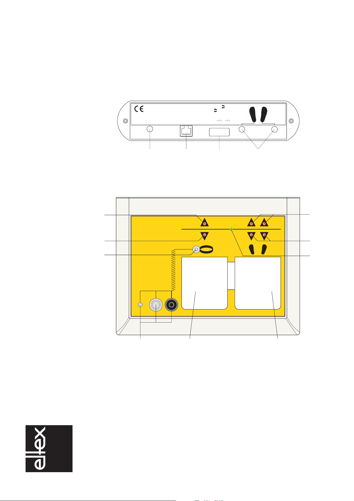
1. Outline of appliance PGT120
Fig. 1:
Connections
PGT120
Z00584y
AC 12 V Door opener 54326781
OFF
ON
mode
voltage
low limits
door opener
high limit
series
1234
Fig. 2:
Outline of
appliance PGT120
Z00585y
Press Press
Hi-Fail
Lo-Fail
OK
PGT 120
Personnel
Grounding
Tester
5d
5c
5b
5a 6a
6b
7
56
89

BA-en-1022-0802_PGT120 7
electrostatic
innovations
Key
1 Socket for external power supply
2 Socket for door opener
3 DIP-switches 1 - 8
4 Sockets for footwear electrode
5 Wrist strap test
5a LED Hi-Fail: upper limit exceeded
5b LED Lo-Fail: below low limit
5c Male snap 3 mm
5d Connections for wrist strap test
Male snap 4 mm
Male snap 10 mm
socket 4 mm
6 Footwear test
6a LED Hi-Fail: upper limit exceeded
6b LED Lo-Fail: below low limit
7 LED OK: measured value in the limit
8 Measuring plate for wrist strap test
9 Measuring plate for footwear test
electrostatic
innovations
8BA-en-1022-0802_PGT120
2. Safety
The PGT120 has been designed, built and tested using state-of-the-art
engineering and has left the factory in a technically and operationally safe
condition. If used improperly, the units may nevertheless be hazardous to
personnel and may cause injury or damage.
Read the operating instructions carefully and observe the safety notices.
The manufacturers will not assume any liability and warranty if the unit is
used improperly.
2.1 Proper use
The PGT120 must only be used to test the leakage resistance.
Permissible are measurements of:
• leakage resistance from hand to soles,
• leakage resistance from hand to leakage bracelet,
• leakage resistance from shoe to shoe.
Other uses are not permitted.
Modifications or changes made to the PGT120 are not permitted.
Use only original Eltex spare parts and accessories.
2.2 Identification of risks and hazards
Possible risks and hazards resulting from the use of the PGT120 are
referred to in these operating instructions by the following symbols:
Warning!
This symbol appearing in the operating instructions refers to operations
which, if carried out improperly, may result in serious personal injury.
Caution!
This symbol appearing in the operating instructions refers to operations
which, if carried out improperly, may result in damage to property.

BA-en-1022-0802_PGT120 9
electrostatic
innovations
2.3 Work and operational safety
• Check the PGT120 in regular intervals for any damage. Any damaged
components must be repaired or replaced before continuing to operate
the unit.
• Always disconnect the power before opening the unit.
2.4 Technical advance
The manufacturer reserves the right to make changes to the technical
specifications without prior notice in order to adapt the units to state-of-
the-art engineering standards. Eltex will provide the latest information on
any changes or modifications in the operating instructions on request.

electrostatic
innovations
10 BA-en-1022-0802_PGT120
3. Installation and assembly
The PTG120 tester has been designed for table and wall mounting. When
used as wall-mounted unit, use our wall bracket which is available as
optional accessory. Mount the wall bracket roughly at chest height to the
wall and attach the PGT120 with the self-adhesive connectors supplied
with the wall bracket.
3.1 Wall mounting plate for the PGT120
Mount the bracket with the plugs and screws supplied at chest height such
that the lower edge has the larger distance from the wall. Stick the self-
adhesive connectors to the wall bracket as shown in the outline drawing.
1 The surface of the plate and the bottom side of the PGT120 have to be
clean, dry and free of grease.
2 Remove protecting foil of the velcro tape pieces and do not touch the
sticky side.
3 Apply the velcro tape pieces according to the picture onto the mount-
ing plate.
4 Remove the second protecting foil of the velcro tape pieces and press
the PGT120 to those pieces. The back edge of the PGT120 needs to
be in line with the upper edge of the mounting plate.
5 After 24 hour curing time the PGT120 can be removed from the wall
mounting plate.
Removing:
Before removing the unit, please remove all plugs on the back of the
PGT120. Hold the unit on the left and the right and tip it forwards. To put
the unit back onto the mounting plate just press the unit back to the velcro
tapes.
Fig. 3:
Wall mounting
plate for PGT120
1 =
velcro tapes
Z00458y
~10 mm
1
BA-en-1022-0802_PGT120 11
electrostatic
innovations
3.2 Power supply
The unit can be operated by the external power supply or by a 9 V battery.
Battery change see chap. 5 Maintenance.
When testing frequently or when using the unit in the "shoes as series cir-
cuit" mode, it is advisable to supply the tester via mains power. Use only
the plug-type power supply included. Connect at the rear socket marked
"AC 12 V". Any battery connected will be automatically disabled as soon
as the jack is plugged in.
Caution!
Please remove the battery when the instrument is not battery operated for
a long period of time.
Warning!
The power supply must not be connected to ground.
3.3 Connections
The connections for cable cords are at the front of the unit.
The connections for power supply, footwear electrode and door opener
are at the rear of the unit.
The resistance of the test person and of the grounding system is tested
when checking the personnel grounding system.
The test person is contacted by operating the measuring plate or by step-
ping on the footwear electrode.

electrostatic
innovations
12 BA-en-1022-0802_PGT120
3.4 Outputs
Additional potential-free contacts allow the documentation of tests and the
control of door openers.
Connect via the 6-pin modular socket (Western RJ12) at the rear of the
unit.
The contact is activated via DIP switch 8.
Fig. 4:
Door opener
6 pin socket
Z00583y
165432
1234
5
6
Door Opener
N/C pin 2 and 3,
N/O pin 3 and 4 Switches as soon as the test object (or both
test objects) are within the limit values.

BA-en-1022-0802_PGT120 13
electrostatic
innovations
4. Operation
4.1 Start-up
The unit can be operated by the external power supply or by a 9 V battery
(see chap. 3.2 Power supply).
The PGT120 has no "ON-OFF" switch. The unit is switched on, when a
measuring plate is pressed or the footwear in series is activated.
The default settings of the unit are set on delivery. With the DIP switches 1
to 8 at the rear of the unit the following options can be programmed:
Default settings (marked bold) and options:
Switch 1 Switch 2 Function
OFF OFF "OR" (wrist strap or footwear test)
ON OFF Only shoes
OFF ON Only wrist strap
ON ON "AND" (wrist strap and shoe test)
Switch 3 Upper limit for single shoe test
OFF 35 MOhm
ON 70 MOhm
Switch 4 Switch 5 Test voltage
OFF OFF 30 V
OFF ON 50 V
ON ON 100V
Switch 6 Footwear test mode
OFF Test according to switch 1 and 2
ON Footwear in series enabled
Switch 7 lower limit
OFF lower limit disabled
ON lower limit enabled
Switch 8 Door opener relay
OFF inacitve
ON active

electrostatic
innovations
14 BA-en-1022-0802_PGT120
4.2 Testing wrist straps separately
DIP switch 1 + 2 at the rear of the unit is set to the "OR" function (default
setting) or the function "only wrist strap".
Put on the wrist strap and connect it via the coil cord to the snap or the
plug (5d, fig. 2) on the left hand side of the unit.
Press the left measuring plate and keep it pressed. An audible signal indi-
cates that the tester is switched on. After a short measuring time the test
result will be indicated by a LED:
The tester will be switched off when the measuring plate is released.
4.3 Testing coil cords separately
A coil cord without a wrist band can be checked as displayed on the front
panel. The connection is made via the 3 mm snap (5c, fig. 2) and the snap
or the plug (5d, fig. 2) on the left hand side of the unit.
DIP switch 1 + 2 at the rear of the unit is set to the "OR" function (default
setting) or the function "only wrist strap".
Press the left measuring plate and keep it pressed. An audible signal indi-
cates that the tester is switched on. After a short measuring time the test
result will be indicated by a LED:
The tester will be switched off when the measuring plate is released.
Green LED "OK" flashes: The resistance is in the range of
750 kOhm to 35 MOhm or 0 to 35 MOhm with
the lower limit switched off.
Red LED "Hi-Fail" flashes:
Audible signal The resistance exceeds the upper limit
of 35 MOhm.
Red LED "Lo-Fail" flashes:
Audible signal The resistance is below the lower limit
of 750 kOhm
(not applicable if the lower limit is switched off).

BA-en-1022-0802_PGT120 15
electrostatic
innovations
4.4 Testing footwear separately
Connect the foot electrode to the sockets with the shoe symbol (4, fig. 1)
at the rear of the unit.
DIP switch 3 at the rear of the unit is preset to the upper limit of 70 MOhm
(can be adjusted to 35 MOhm).
DIP switch 1 + 2 at the rear of the unit are set to the "OR" function (default
setting) or to the function "only shoes".
Stand with both shoes on the footwear electrode while pressing the right
measuring plate and keep it pressed. An audible signal indicates that the
tester is switched on. After a short measuring time the test result will be
indicated by a LED:
The tester will be switched off when the measuring plate is released.
Green LED "OK" flashes: The resistance of both shoes is in the range of
100 kOhm to 70 MOhm (35 MOhm) or 0 to 35
MOhm with the lower limit switched off.
Red LED "Hi-Fail right" flashes:
audible signal The resistance of the right shoe exceeds the
upper limit of 70 MOhm (35 MOhm).
Red LED "Hi-Fail left" flashes:
audible signal The resistance of the left shoe exceeds the
upper limit of 70 MOhm (35 MOhm).
Red LED "Lo-Fail" right flashes:
audible signal The resistance of the right shoe is below the
lower limit of 100 kOhm
(not applicable if the lower limit is switched off).
Red LED "Lo-Fail" left flashes:
audible signal The resistance of the left shoe is below the
lower limit of 100 kOhm
(not applicable if the lower limit is switched off).
electrostatic
innovations
16 BA-en-1022-0802_PGT120
4.5 Testing wrist straps and footwear at the same time
DIP switch 1 + 2 at the rear of the unit is set to the AND function.
Put on the wrist strap and connect it via the coil cord to the snap or the
plug (5d, fig. 2) on the left hand side of the unit.
Connect the footwear electrode to the sockets with the shoe symbol
(4, fig. 1) at the rear of the unit.
DIP switch 3 at the rear of the unit is preset to the upper limit of 70 MOhm
(can be adjusted to 35 MOhm).
Stand with both shoes on the footwear electrode while pressing one
measuring plate and keep it pressed. An audible signal indicates that the
tester is switched on. After a short measuring time the test result will be
indicated by a LED:
Warning!
The green LED only flases when the resistance footwear and the
resistance wrist strap are between the limits.
If the wrist strap or the footwear are out of range, the fault will be indicated
by audible and visual (red LED) signals.
Evaluation of the signal identical to the separate tests.
The tester will be switched off when the measuring plate is released.
Green LED "OK" blinking: The resistance of both shoes is in the range of
100 kOhm to 70 MOhm (35 MOhm) and the
resistance wrist strap is in the range of
750 kOhm to 35 MOhm. If the lower limit is
switched off, the lower limit starts at 0 Ohm.

BA-en-1022-0802_PGT120 17
electrostatic
innovations
4.6 Footwear test as series circuit (hands-free mode)
Connect the enclosed footwear electrode to the sockets showing the shoe
symbol (4, Fig. 1) at the rear of the unit.
DIP switch 6 at the rear of the unit set in the mode "ON footwear test in
series enabled". The upper limit cannot be switched over.
The footwear test can be made without activating the measuring plate,
e.g. in combination with a turnstile or a similar singularization system.
Resistance is measured between left and right shoe.
Stand on the footwear electrode with both shoes. If the shoes are conduc-
tive, an audible signal will indicate that the tester is switched on. The test
result will be displayed on one of the LEDs after a brief measurement
period.
No individual error measurements will be displayed in this operating
mode. The defective shoe can be identified by pressing the measuring
plate again. The upper limit for each shoe is set for 70 MOhm.
The tester will be switched off when stepping off the footwear electrode.
Green LED "OK" flashes: The sum of resistance of both shoes is within
the range 200 kOhm to 140 MOhm, or 0 to
140 MOhm with the lower limit switched off.
Red LED "Hi-Fail" flashes:
audible signal The resistance of the series circuit exceeds the
upper limit 140 MOhm.
Red LED "Lo-Fail" flashes:
audible signal The resistance of the series circuit falls below
the lower limit 200 kOhm
(not applicable if the lower limit is switched off).

electrostatic
innovations
18 BA-en-1022-0802_PGT120
5. Maintenance
The PGT120 is maintenance-free.
To avoid any impairment of the proper function, keep it clean and dirt-free.
Use the calibration unit PGT120.102 (optional) to test the limit values of
the PGT120.
Battery change
Insert the 9 V battery into the battery compartment and connect it.
Caution!
Please remove the battery when the instrument is not battery operated for
a long period of time.

BA-en-1022-0802_PGT120 19
electrostatic
innovations
6. Warranty
The units are warranted for a period of 12 months provided that the opera-
ting conditions have been maintained, that the units have not been tem-
pered with and that the units show no mechanical damage.
The warranty applies only if the operating and assembly instructions spe-
cified by Eltex have been observed. The warranty period begins on the
date of delivery.
In the event of defects occurring during the warranty period, the units or
defective components will be repaired at Eltex. Defective components will
be replaced and installed free of charge.
If repairs are required at the customer's premises, the costs for sending a
technician (travel, travel time, expenses) will be charged to the customer.

electrostatic
innovations
20 BA-en-1022-0802_PGT120
7. Technical specifications PGT120
Operating voltage 9 V E 6F22 battery
external power supply 230 V I 50 Hz
Test voltage
(open circuit)
switchable
30 V ±10%
50 V ±10%
100 V ±10%
Operating conditions 15°C ... 40°C,
up to 75 % relative humidity, non condensing
Storage conditions -10°C ... 60°C,
up to 85 % relative humidity, non condensing
Operating mode
switchable separate test OR
test in parallel AND
only wrist strap
only shoes
hands-free-mode
Connections
Wrist strap
footwear electrode
Door opener / counter
External power supply
10 mm snap, 4 mm snap, 4 mm socket
2 sockets 4 mm
western socket 6-pin RJ-12
socket for the external 12 VAC supply
Measuring ranges
(switchable)
Wrist strap
Single shoes
Shoes,
in series circuit
Tolerance
750 kOhm ... 35 MOhm (0 Ohm ... 35 MOhm)
100 kOhm ... 70 MOhm (0 Ohm ... 70 MOhm)
(100 kOhm ... 35 MOhm) (0 Ohm ... 35 MOhm)
200 kOhm ... 140 MOhm (0 Ohm ... 140 MOhm
(Hands-free-Modus)
±10%
Signals
Green LED
Red LED’s and buzzer
Door opener
Door opener time
"OK"
"Hi-Fail" oder "Lo-Fail"
potential-free change-over contact "OK"
3 seconds
Contact ratings
Max. voltage
Max. current
Max. power
60 V
2A
50 VA
Weight approx. 500 g
Dimensions 150 x 200 x 63 mm
Serial number on the unit side
Table of contents
Popular Test Equipment manuals by other brands


Rohde & Schwarz
Rohde & Schwarz R&S CMU-Z10 manual

Hameg
Hameg HM 307 manual

Associated Research
Associated Research HypotULTRA 7804 quick start guide

Agilent Technologies
Agilent Technologies 86100A Release notes

Helmut Singer Elektronik
Helmut Singer Elektronik 2467B manual

Sealey
Sealey BT91/3.V2 instructions


