R&S®CMU-Z10/-Z11/-Z12/-Z13 Short Description
1158.9537.12 9 E-6
The USB feed through must be connected to the test instrument and the MS
under test using two appropriate, shielded USB cables according to standard
USB 1.1. At present USB 2.0 is not supported.
Note: Connecting USB cables and shielding
The USB feed through causes no radiation that might impair the
shielding effect of the chamber. To avoid interference from the
external connecting line, use a shielded USB cable that is
equipped with EMI ferrite attenuators.
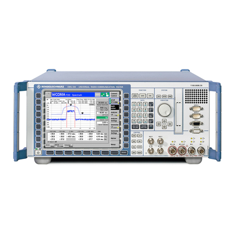
Note: The RF transmission and the coupling factors depend on the RF connection between the
antenna coupler and the RF input/output of the test instrument (R&S®CMU 200). It is
recommended to use the high-quality RF cable supplied with R&S®CMU-Z10 for the
connection. See also section Coupling Factors on p. 9f.
Coupling Factors
The RF signal from the MS under test is attenuated on its way from the antenna coupler to the test
instrument. Analogously the RF generator signal from the test instrument is received by the MS under
test with a definite attenuation. We define the coupling factors for the two signal directions as the
difference between transmitted and received powers:
Output coupling factor/dB = <RF generator level of the R&S®CMU 200>/dBm
– <Received input level determined by the MS (RxLev)>/dBm
Input coupling factor/dB = <Transmitter output power of the MS>/dBm
– <RF input power measured at the R&S®CMU 200>/dBm
Once the coupling factors are known for a given mobile type and RF connection they can be reported to
the R&S®CMU 200 as external attenuation factors (Ext. Att. Input, Ext. Att. Output). The tester will then
correct all power measurements by the reported input coupling factor and increase its RF generator
level to compensate for the output coupling factor.
Note: The coupling factors depend on the position of the MS antenna relative to the active
coupling zone of the antenna coupler and therefore on the mobile type (for more
information see data sheet). Compiling a complete list of coupling factors for all mobile
types is not practicable, however, it is sufficient to determine the coupling factors once for
all mobiles of the same type.
In order to re-use the coupling factors for different mobiles of the same type, they must be
put into exactly the same position on the base plate or in the holder of the antenna coupler;
see section Replacing the Base Plate on p. 14 ff. Moreover, to exclude any additional
source of errors the coupling factors for a particular mobile type must be determined using
a fully functional and proven device ("golden" mobile phone).
The sign of the input and output coupling factors was chosen in accordance with the
definition of external input and output attenuation factors (Ext. Att. Input, Ext. Att. Output) in
the R&S®CMU 200.
