eltima electronic Jokie 2 User manual
User's Manual
light barrier

Ver: 1.0.3
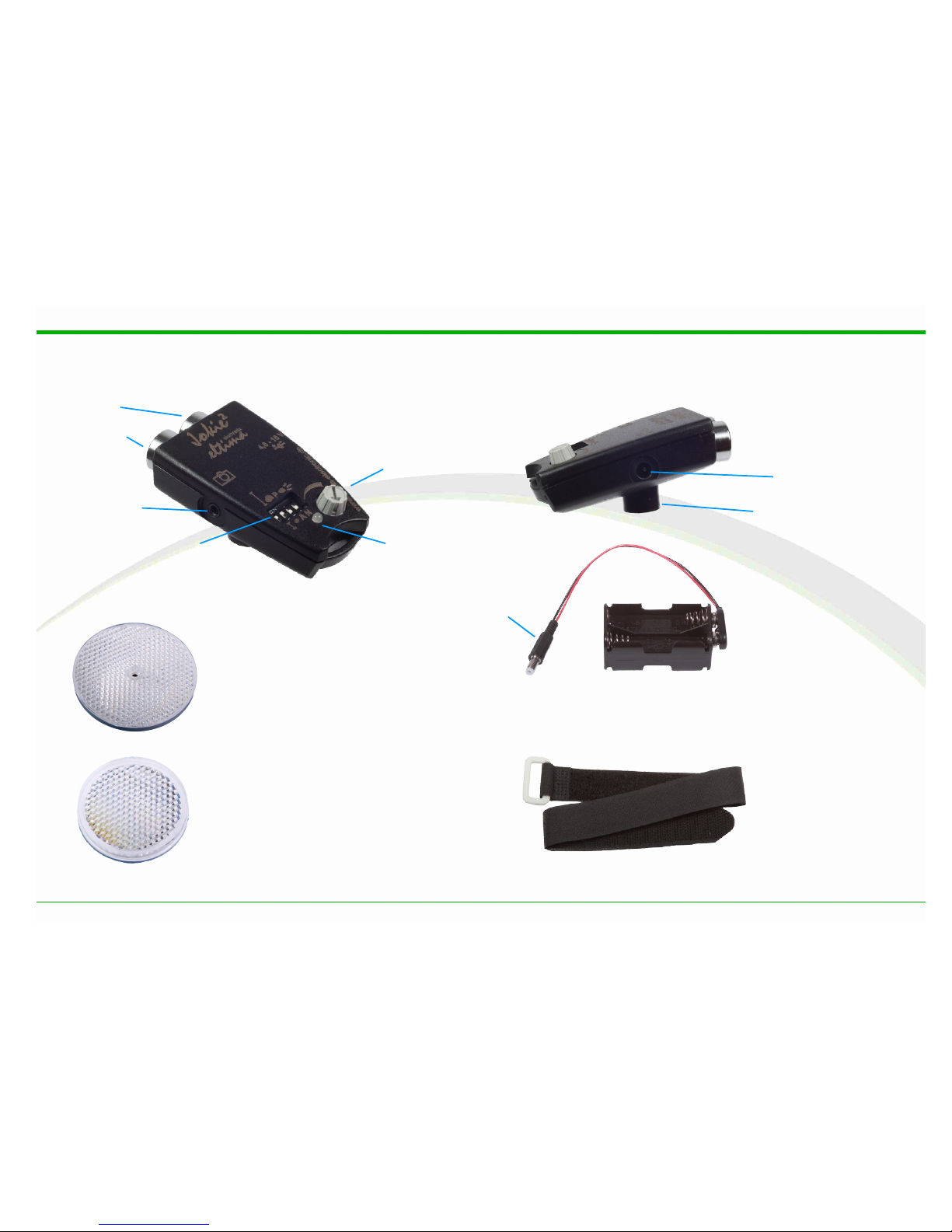
Description of components
Description of components
© eltima electronic 2013 3
velcro tape
tripod socket
infrared
transmitter
camera socket
operating mode switch
80 mm reflector
DC-plug
battery case
40 mm reflector
ED
receiver
DC-plug
potentiometer
light barrier

Content
Content
Description of components.................................................3
Content..............................................................................4
Intro uction.......................................................................5
Intended purpose..................................................................5
Symbols...............................................................................5
Maintenance and storage........................................................5
Quick Start.........................................................................6
Getting started......................................................................6
Functional concept.............................................................7
Reflex light barrier.................................................................7
The light beam......................................................................8
Reflectors.............................................................................9
Sensitivity..........................................................................10
Operating mo es..............................................................11
Reach and sensitivity...........................................................11
Release delay, lag time........................................................14
Thunderstorm photography...................................................15
Detecting projectiles............................................................15
Keep-active mode................................................................16
Wake-Up............................................................................16
Taking pictures with Jokie²..............................................17
Setup and alignment of the light barrier.................................17
Setup.................................................................................17
Alignment of the light barrier................................................17
Finding the midpoint of the reflector......................................18
Connecting the camera.........................................................18
Important camera settings....................................................18
Auto-focus..........................................................................18
Aligning the camera towards the camera and the subject.........19
Focal plane parallel to light beam..........................................19
Focal plane parallel to flight path...........................................20
Using the geometry of the subject.........................................20
Working with the sensitivity of the light barrier.......................21
Taking pictures of small objects.............................................21
Blanking out of smaller objects..............................................21
Taking pictures without reflectors..........................................22
Connections.....................................................................23
Camera connection..............................................................23
Power supply......................................................................23
Specifications...................................................................24
Type..................................................................................24
Measurements.....................................................................24
Weight...............................................................................24
Power supply......................................................................24
Power consumption..............................................................24
Service life with one set of batteries......................................24
Reach................................................................................24
Response time....................................................................24
Scope of delivery.................................................................24
Notes...............................................................................25
4© eltima electronic 2013
Intro uction
Introduction
Dear client,
thank you for purchasing our light barrier . For you,
being an ambitious photographer, it shall be a reliable tool
that is both handy and easy to operate.
Please do not hesitate to contact us if you should miss
anything or have further improvement proposals. Only like
this the product will be able to develop to fully meet your
requirements.
Please read this manual carefully before using the light
barrier. It is supposed to get you familiar with operating
the system and all its functions. In this way you will be
able to use all the advantages offers.
Inten e purpose
This light barrier was solely built to release photo-
graphic cameras, flashes and filming devices. Please do
only use it for this purpose!
Symbols
Symbol for tips concerning the handling of the de-
vice.
Important advice concerning the function of the de-
vice.
Important advice to prevent damage of the device or
connected devices.
Maintenance an storage
• is not waterproof and therefore neither suitable
for use in rain nor under water. Please contact the man-
ufacturer immediately in case it should get wet. Water
drops can be wiped off with a dry cloth.
•Do not drop it or expose it to shocks.
•This device is a precise electrical/optical system. Do not
try to make alterations yourself.
•Please remove the batteries in case you should not use
the device for some time. This will prevent any leaking
of the batteries.
•Please clean the lenses occasionally with a soft cloth.
© eltima electronic 2013 5
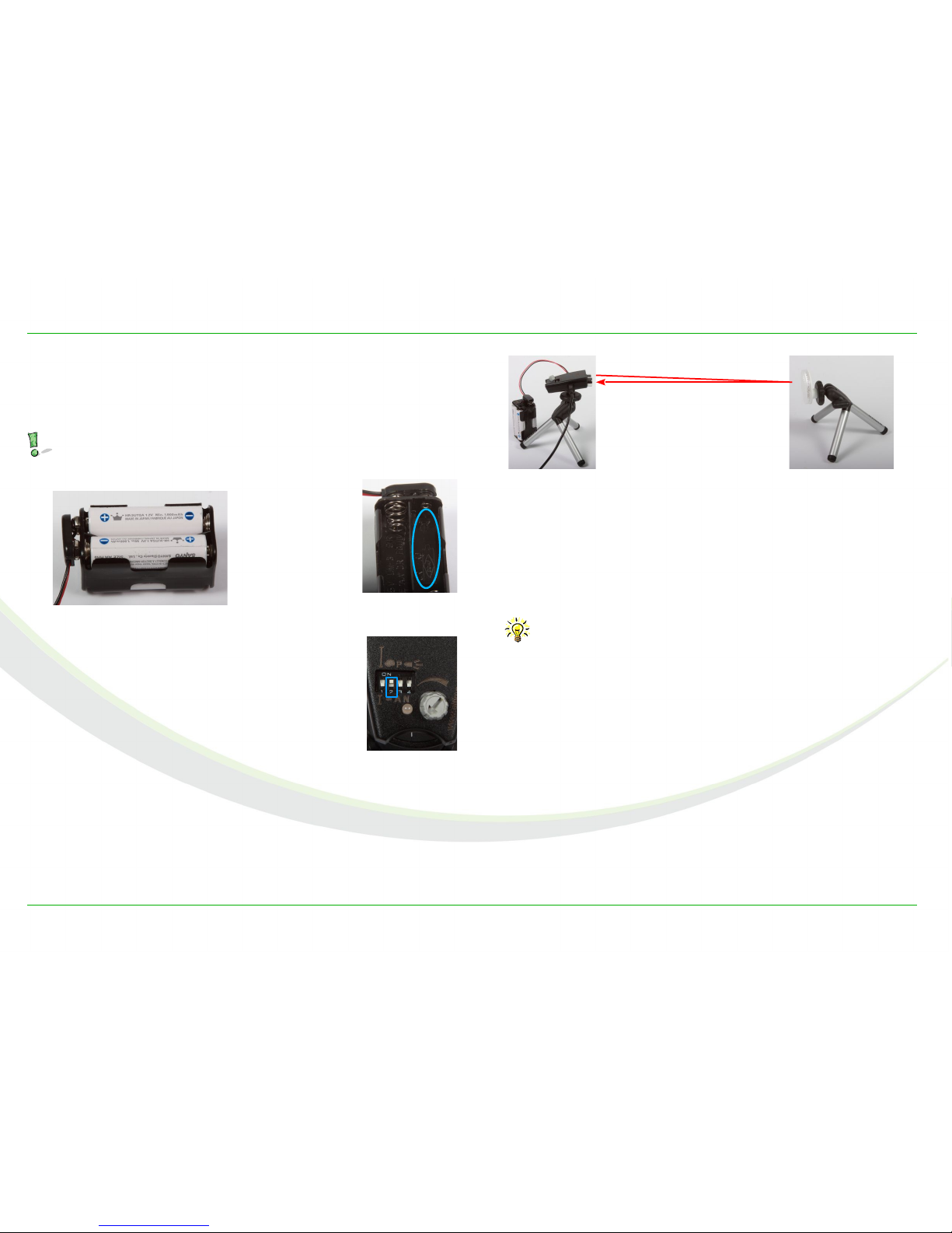
Quick Start
Quick Start
Getting starte ...
•Insert four batteries or accumulators into the battery re-
tainer.
Please observe the correct polarity, which is shown
at the bottom of every battery compartment.
•Put switch 2 of the mode switch to ON,
all others to OFF.
•Turn the potentiometer left until the end
stop.
•Install the light barrier and the 40mm reflector on one
tripod each.
•Plug the DC-plug in the DC-plug of the light barrier. At
this point the ED will shine green.
•Plug the 2.5mm jack plug of the camera adapter unit
(adapter unit available as accessories) into the camera
socket.
•Position the light barrier and the reflector opposite to
each other at a distance of 60 – 80 cm.
Note: This distance is chosen randomly and it is
neither the shortest nor the largest possible dis-
tance between camera and reflector.
•Align the infrared beam towards the reflector until the
ED goes out. The light barrier is ready for use now.
•Plug the other end of the camera adapter unit into the
remote control socket of your camera.
•Switch the auto focus of your camera to “manual“.
•Move your hand or another object through the light
beam. The camera will be released.
6© eltima electronic 2013
Image 1: Battery case
Image 3: mode
switch
Image 4: Setup
ca. 60 – 80 cm
Image 2:
polarity marking
Functional concept
Functional concept
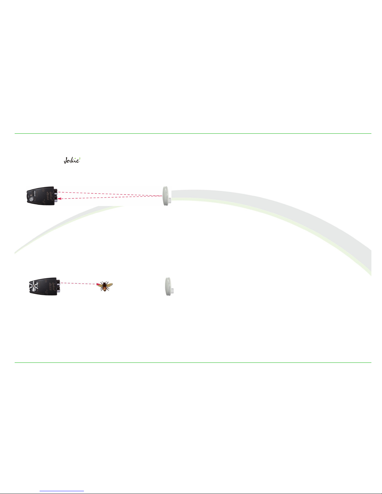
Reflex light barrier
The light barrier is build according to the principle of
a reflex light barrier. Sender and receiver are in the same
housing.
The IR-transmitter emits an infrared light pulse train,
which is reflected by a reflector and thus thrown back to
the receiver.
If an impulse is missing or is received very weak, for ex-
ample because an object is in the way of the light beam,
an electrical switch is closed and the connected device is
released.
This principle of function offers several advantages. First of
all only one device, the light barrier itself, needs power
supply, the other side, the reflector, is passive.
In addition the latter is very solid and easy to handle, at-
tach and camouflage. Furthermore it is possible to use any
object as reflector, for example also the subject itself.
So, in some cases, the light barrier can also be operated
without reflectors.
© eltima electronic 2013 7
Image 5: reflex light barrier
Image 6: ight beam is interrupted
Functional concept
The light beam
As described above the light barrier emits quickly succes-
sive invisible infrared light impulses, which are reflected by
a reflector and get back to the receiver. The latter expects
a certain minimum amount of the emitted light back for
each impulse.
While using the light barrier with a reflector, the received
amount of light is above a fixed threshold and the ED is
off. If the amount of light is below the threshold because
an object weakens the light beam or one impulse is miss-
ing since a large object is in the way of the beam, the ED
lights up and the connected device is released.
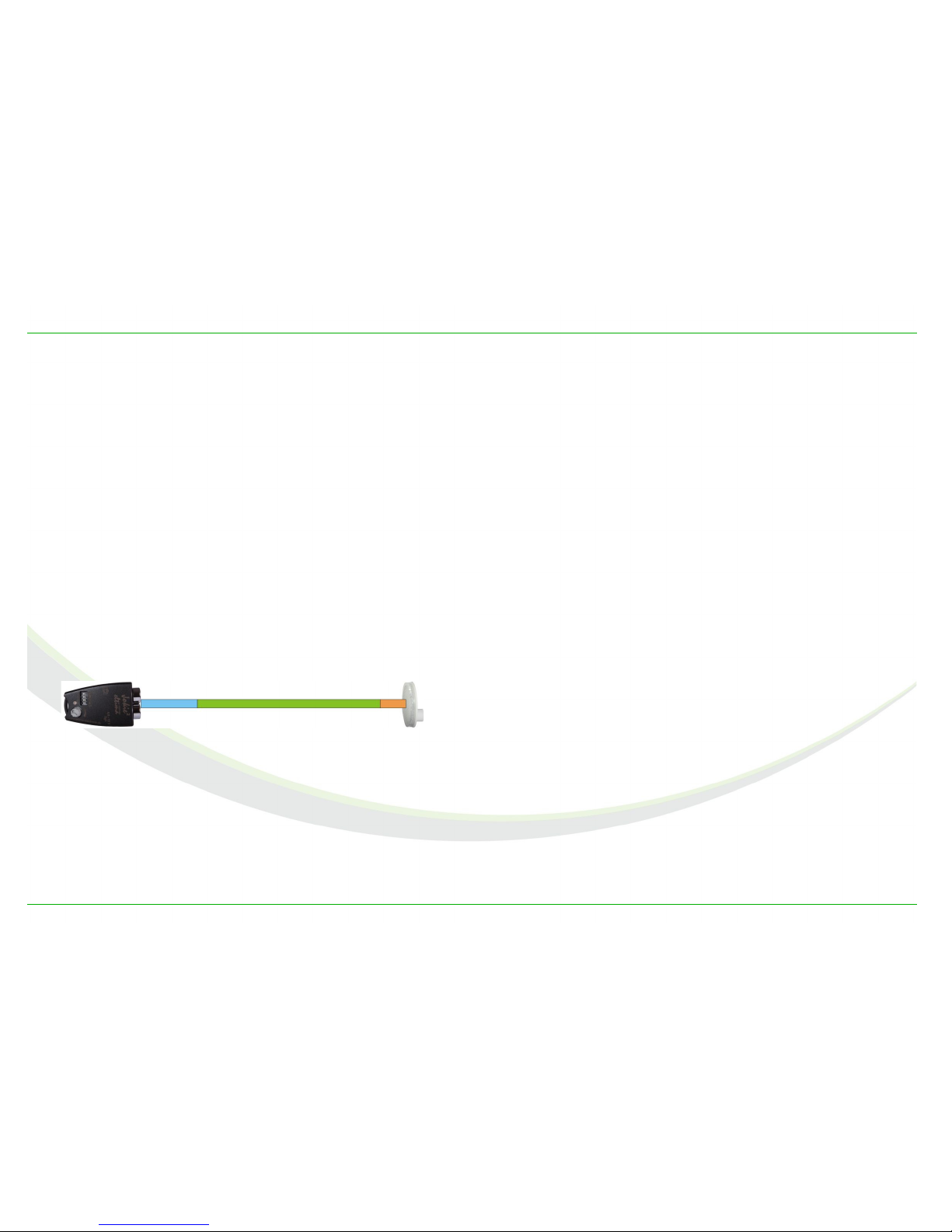
Due to the sending- and receiving characteristics of the
optical components, combined with the reflection charac-
teristics of the reflectors, the working distance between
the light barrier and the reflector can be roughly divided in
three sections.
The green middle section is the “normal“ working area of
the light barrier. Depending on the reflector used and the
working distance, one can assume a diameter of the beam
of 3-5 mm. The objects to be detected be the light barrier
need to meet and interrupt this beam. The small diameter
brings a very precise and repeatable switching point of the
light barrier.
The sensitivity of the system is highest in the green area.
In the orange area, closer to the reflector, the sensitivity
decreases and it's not sure that smaller objects will be de-
tected.
In the blue area that is close to the light barrier objects
may work as reflectors themselves. Therefore its is possi-
ble that a bright, well reflecting object may reflect the light
better than a reflector that is far away. As a result of that
the threshold value mentioned above is not undershot and
thus the light barrier not released, although an object is
positioned in the light beam. For that reason the light bar-
rier should be set up so that the object do preferably not
move through the blue area.
Consequently the light barrier can be operated without a
reflector in the blue area, which may be a great advantage
in some cases. The reach of the light barrier then depends
basically on the size and the reflection characteristics of
the object, see section Taking pictures without reflectors.
8© eltima electronic 2013
Image 7: Sections of the light beam

Functional concept
Reflectors
Two retroreflectors are included in the scope of delivery of
the light barrier . They consist of a circular plate with
many honeycombed
triple prisms.
One characteristic of
triple prisms is that they
reflect light back into
the direction it came
from, shifted for an
edge length. Image 8
shows the principle of
function of a single
triple prism.
Due to this characteristic a retroreflector does, in contrast
to plane mirrors, not have to be aligned exactly into the
direction of the light barrier. It is totally sufficient when it
looks roughly towards the latter. Solely for reaching the
maximum working distance the reflector should be aligned
precisely.
© eltima electronic 2013 9
Image 8: Triple prism

Functional concept
Sensitivity
It is the sensitivity that determines how big an object has
to be at the least in order to be detected by the light barri-
er. Working with high sensitivity, very small objects can be
captured, with lower sensitivity, only larger objects will be
registered and smaller ones remain unnoticed.
In the case of the light barrier the sensitivity cannot
be adjusted. Nevertheless it can be influenced by the
choice of reflector, working distance and transmission
power of the IR-emitter.
The smaller the reflector, the less light will be reflected
and returned to the receiver, see section Reflectors. When
less light gets back to the receiver, the amount of light is
the closer to the threshold value. Then already a fairly
small object will be enough in order to weaken the light
beam to such an extent that the amount of light will be
below the threshold value.
The larger the working distance, the more light intensity is
lost before getting back to the receiver and therefore the
amount of received light is closer to the threshold. Here a
small object will be enough as well in order to weaken the
light beam so that the amount of light will fall below the
threshold value.
The less light is emitted by the IR-sender, the less will be
returned to the receiver and thus the smaller the objects
can be and still bring about a release of the camera.
Facit: The smaller the reflector is, or the larger the
working distance or the smaller the transmission
power of the IR sender, the higher the sensitivity
is.
The other way around, the larger the reflector is, or
the smaller the working distance or the larger the
transmission power of the IR sender, the lower is
the sensitivity of the light barrier.
10 © eltima electronic 2013
Operating mo es
Operating modes
Reach an sensitivity
The characteristics reach and sensitivity are closely con-
nected.
For a high reach the IR sender has to emit a high amount
of light due to the loss of light on the longer way back.
To achieve a high sensitivity, the IR sender has to emit
less light.
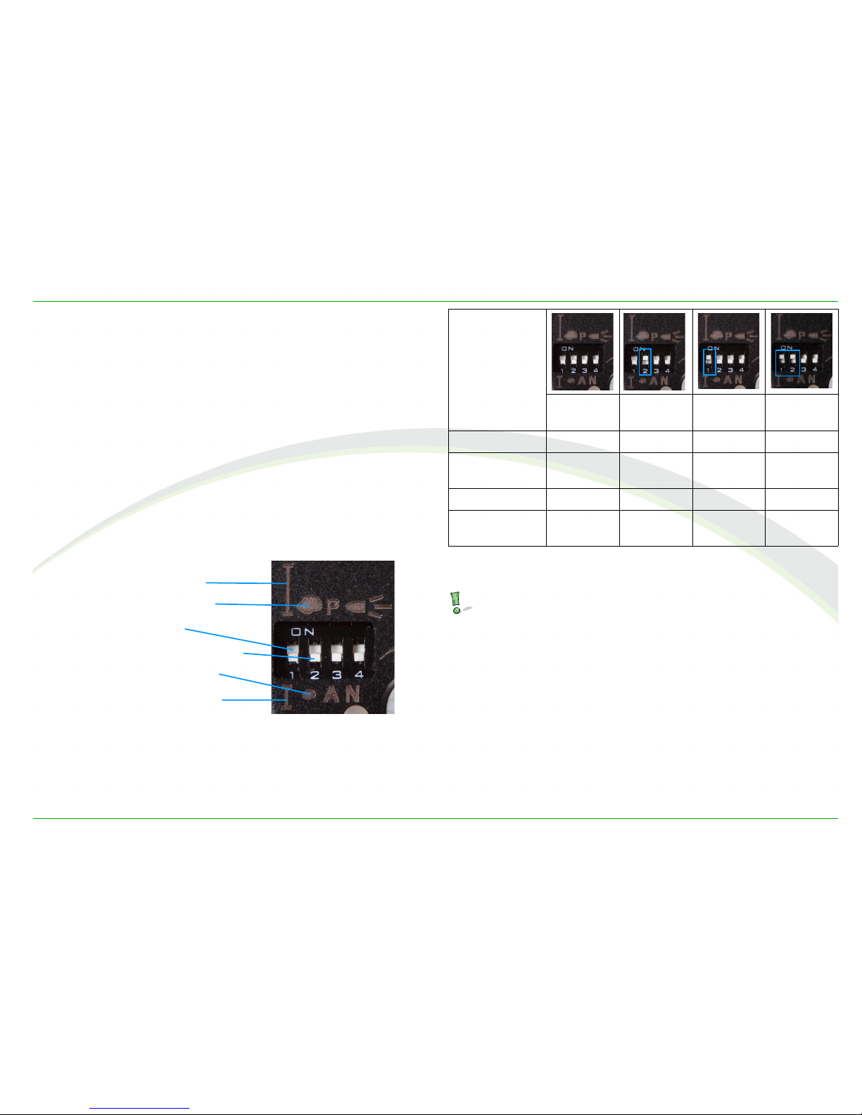
In order to do justice to both requirements, the transmis-
sion power of the IR sender can be adjusted in four levels
using the operating mode switch, thus resulting in four
possible sections of reach.
Table 1 roughly shows the coherence.
Switch position
small,
small
small,
large
sarge,
small
sarge,
large
Reach minimum small high maximum
Minimum size
of object
very small small medium large
Sensitivity maximum high small minimum
Power of IR
sender
minimum small high maximum
Table 1: Effect of different switch settings
The operating mode switch can be turned with a pen,
ballpoint pen or with a pair of tweezers that is not too
peak.
© eltima electronic 2013 11
Image 9: Switch symbols
Symbol for large reach
Symbol for large objects
Symbol for a small reach
Symbol for small objects
Switch for the reach
Switch for the size of objects

Operating mo es
Table 2 shows the maximum reaches when using reflectors
offered by eltima electronic.
The 20mm reflector that is listed in the following ta-
bles is not included in the scope of delivery of !
Size of
reflector
[mm]
Switch position Max. Reach
[m]
Reach Object
20 small small 0,3
small large 0,45
large small 2,8
large large 5
40 small small 0,45
small large 1
large small 6,5
large large 9
80 small small 1,3
small large 8
large small 12
large large 16
Table 2: Maximum reach for different sizes of reflectors
The following tables show how the sensitivity, which deter-
mines the smallest detectable object in mm, depends on
the size of the reflector and the working distance (distance
between light barrier and reflector), based on the four sec-
tions of reach.
Switch position: Reach small, object small
working istance
[m]
Reflector
20 mm 40 mm 80 mm
0,1 5 --- ---
0,2 5 5 ---
0,3 0,5 3 ---
0,4 --- 0,5 26
0,6 --- 0,5 20
0,8 --- --- 12
1 --- --- 10
1,3 --- --- 1
Table 3: Sensitivity in mm, using switch position: small, small
12 © eltima electronic 2013

Operating mo es
Switch position: Reach small, object large
Working istance
[m]
Reflector
20 mm 40 mm 80 mm
0,2 7 --- ---
0,3 5 --- ---
0,4 0,5 12 ---
0,6 --- 8 ---
0,8 --- 4 ---
1 --- 1 26
2 --- --- 23
3 --- --- 15
5 --- --- 5
8 --- --- 1
Table 4: Sensitivity in mm, using switch position: small, large
Switch position: Reach large, Object small
Working istance
[m]
Reflector
20 mm 40 mm 80 mm
1 5 20 50
2 4 18 40
3 0,5 15 36
4 --- 12 36
5 --- 5 30
6 --- 0,5 30
8 --- --- 30
Table 5: Sensitivity in mm, using switch position: large, small
© eltima electronic 2013 13
Operating mo es
Switch position: Reach large, object large
Working istance
[m]
Reflector
20 mm 40 mm 80 mm
2 7 20 ---
3 7 18 ---
4 5 18 ---
5 3 18 50
6 --- 18 45
8 --- 12 36
10 --- --- 30
12 --- --- 23
14 --- --- 12
16 --- --- 8
Table 6: Sensitivity in mm, using switch position: large, large
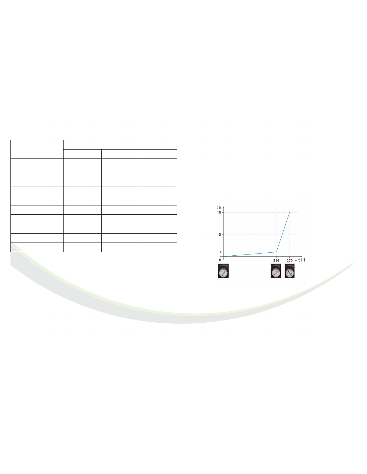
Release elay, lag time
Using the potentiometer one can, if needed, set a delay
time. The effect will be that the connected camera or the
speedlight, based on the interruption of the light beam, is
released later according to the programmed delay.
One can set the delay on the lowest possible level the light
barrier offers, that being 20µs, from the left side, up to a
maximum of 10 seconds, from the right side.
A strongly bent characteristic curve allows a very precise
setting of up to one second, afterwards a rough setting of
up to 10 seconds.
The delay time is active in all operating modes except for
the passive-mode, see Thunderstorm photography.
14 © eltima electronic 2013
Image 10: delay time curve
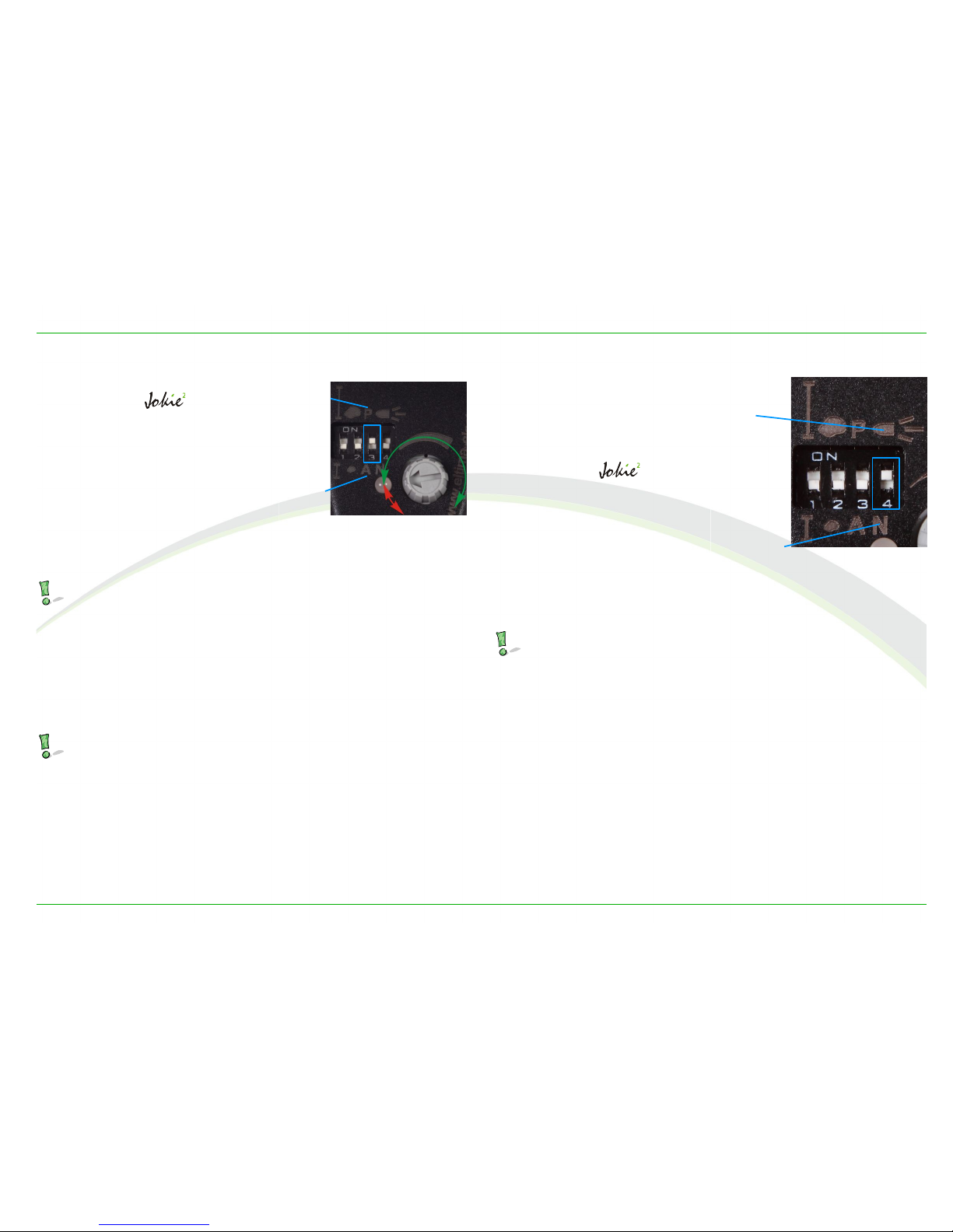
Operating mo es
Thun erstorm photography
By the help of switch 3, the
light barrier can be
switched into the passive
mode. The IR emitter diode is
turned off and the light barri-
er only reacts to fast changes
of the surrounding light, as
would be the case with light-
ning.
The sensitivity is set using
the potentiometer.
Please do only use the green section (starting at the
ED) in order to set the sensitivity, not the red one!
At the left end of the green section the camera will be
released already when smaller or distanced lightning oc-
curs, at the very right end only in case of strong lightning.
In order to photograph in the passive mode, the light bar-
rier is mounted on a tripod and positioned into the direc-
tion of the thunderstorm.
The operating mode switch can be turned with a pen,
ballpoint pen or with a pair of tweezers that is not too
peak.
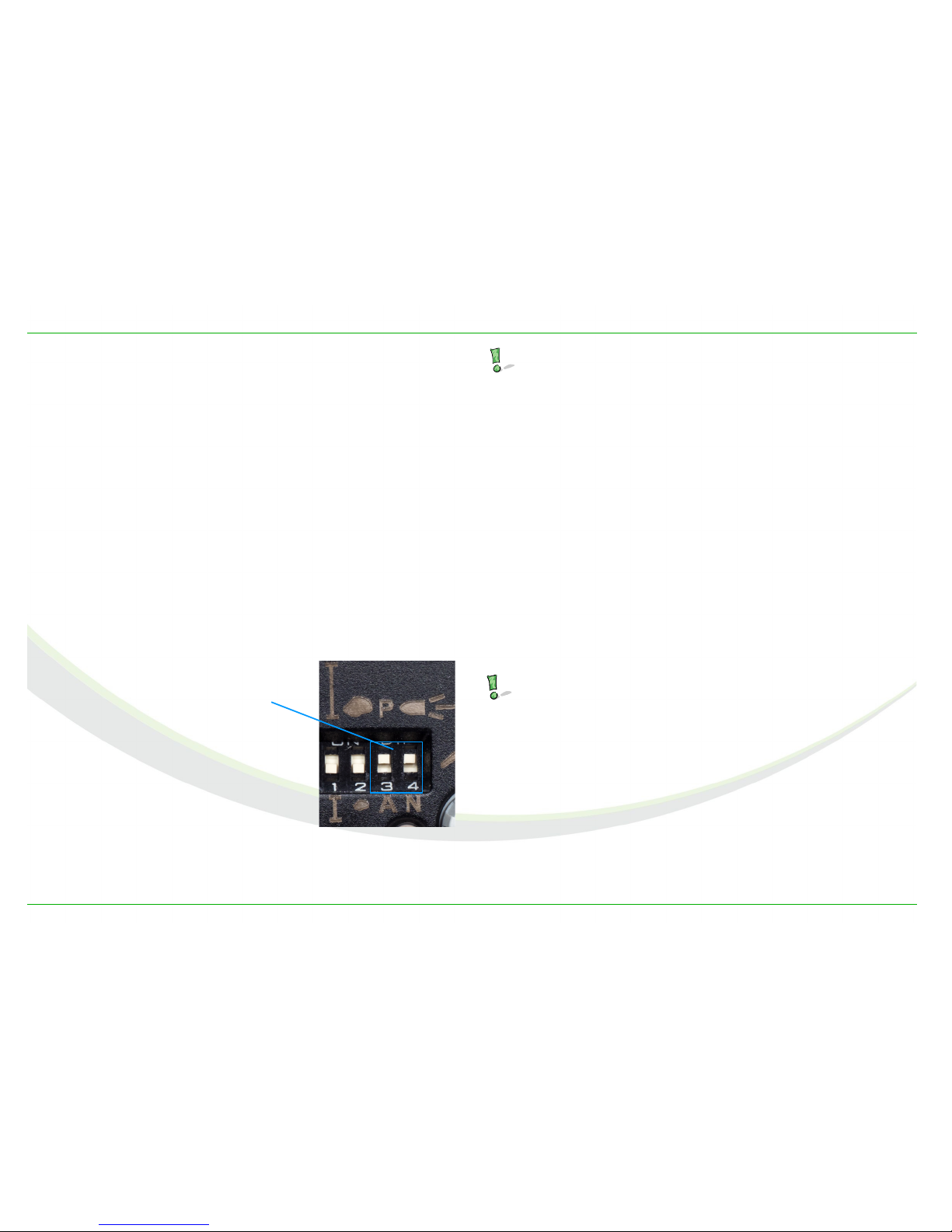
Detecting projectiles
In order to capture ob-
jects moving at a speed of
more than 200 m/s or
720 km/h, as for example
projectiles of guns, the
light barrier must
be switched to the „bullet
mode“ using switch 4.
The reach is reduced to
about 8m when using a
80mm reflector. Switch 1
does not have any effect
in this operating mode. Using switch 2 the reach and sen-
sitivity can be set for the bullet mode.
For all objects that are moving slower than the speed
stated above the normal mode should be used.
© eltima electronic 2013 15
Image 11: Passive mode
Passive
Active
Image 12: bullet mode
bullet
mode
N – normal
mode
Operating mo es
Keep-active mo e
All cameras have a certain lag time, that varies depending
on the camera model.
This lag time can be annoying because the picture is cap-
tured later by this time, measured from the moment of in-
terruption of the light barrier. Depending on the camera
the lag time can be from 10 to 300 ms.
In addition the lag time varies from one release to the
next. This variation also depends on the camera model.
Some of them have a variation of a few milliseconds, oth-
ers varies some tenths of milliseconds.
Using the keep-active mode of the light barrier Jokie² the
lag time can be reduced significantly. At the same time the
variation is also reduced significantly.
To activate the keep-active mode switch on the switches 3
and 4, see Image 13.
This mode behaves as if the the release button is
pressed halfway all the time. Therefore the review of
pictures is not possible, as well as life view modes, if
existing.
To review the pictures switch off the keep-active
mode or disconnect the camera from the light barrier.
Wake-Up
Most cameras and speedlights activate the power saving
mode after a certain period of time. In the case of some
devices this function cannot be turned off using the cam-
era settings.
To keep these devices “awake“, the light barrier activates
the camera every 10 minutes similar to pressing the shut-
ter button halfway down.
The wake-up function is always active, it can not be
turned on or off.
16 © eltima electronic 2013
Image 13: activating the keep-active mode
Switches 3 and 4
to ON
Taking pictures with Jokie²
Taking pictures with Jokie²
Setup an alignment of the light barrier
In nature photography, light barriers are usually set up in
places where one knows exactly where and in which direc-
tion the subjects (animals) move. Examples are feeding
places, nests, dens, runways etc. On the other hand, in ex-
perimental photography, the light beam crosses the flight
path of the desired object.
Setup
Usually light barrier and reflector are mounted on tripods.
The more solid the setup is, the less wrong releases will
occur.
Install the reflector in a place outside of the image section
and position it so that it faces the light barrier. A precise
alignment is only necessary if you aim to work with the
maximum reach.
After that the light barrier should be mounted and the
power supply as well as the camera connection cable be
connected.
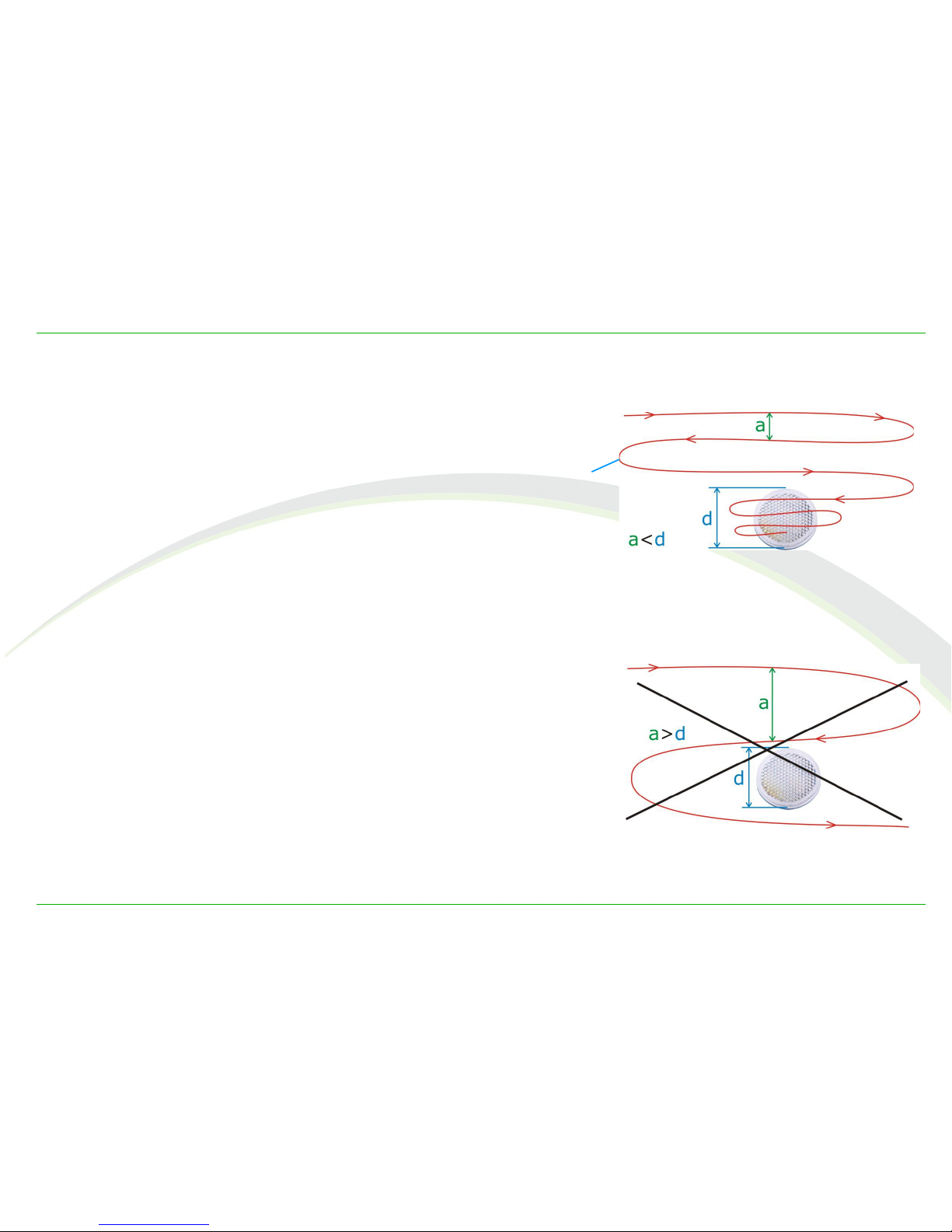
Alignment of the light barrier
At first point with the beam above the reflector and move
the light beam – in a meandering pattern – into the direc-
tion of the reflector. The distance a of the horizontal routes
should be smaller than the diameter d of the reflector (im-
age 14), otherwise you might move the light beam around
the reflector and miss it (image 15).
Meanwhile watch the ED of the light barrier. Without re-
flection it is turned on. As soon as the beam hits the re-
flector, the ED will go out.
Meanwhile watch the ED of the light barrier. Without re-
flection it ON. As soon as the beam hits the reflector, the
ED will be OFF.
© eltima electronic 2013 17
Image 14: Finding the reflector
“way” of the beam to the
reflector
Image 15: missing the reflector

Taking pictures with Jokie²
Fin ing the mi point of the reflector
Next you should look for the midpoint of the reflector and
direct the light barrier towards it. In order to do so, you
swing the light barrier slowly towards the right until the
ED is on again – please remember this point. Afterwards
you turn the light barrier left, until the light beam is be-
yond the reflector and the ED is on. The horizontal mid-
point is in the middle of these two points.
Now, starting from the horizontal midpoint, you also align
the light barrier towards the vertical midpoint. You will find
the latter as described above, only this time in the vertical
direction.
Connecting the camera
At this point the light barrier is aligned, so that you can
connect the camera. After that the system is prepared and
ready to take pictures – the camera will be released if the
light beam is interrupted.
Important camera settings
Auto-focus
When photographing with light barriers it is mandatory to
switch the auto-focus of the camera to manual. By not do-
ing this, the camera will probably not release.
This principle applies for all operating modes of the light
barrier.
Reason: The auto-focus is too slow for the most high-
-speed situations, even though now days systems are al-
ready very fast. The light barrier replaces the auto-focus!
Focus the lens to a point were you expect that your sub-
ject may be, when the camera takes the picture. The sub-
jects speed, the moving direction as well as the cameras
lag time must be taken in account.
According to the speed and the lag time of the camera, the
subject will travel a certain distance away from the beam.
The right focus point has to be determined by a number of
trials.
18 © eltima electronic 2013

Taking pictures with Jokie²
Aligning the camera towar s the camera an the
subject
Wherever possible the camera´s focal plane should be par-
allel to the light barrier´s light beam or parallel to the
flight path of the desired subject. This setting increases
the success rate considerably, especially if you are gather-
ing your first experiences with light barriers.
Focal plane parallel to light beam
If the camera´s focal plane is parallel to the light beam,
the subject can be depicted sharply from the left to the
right edge of the image, no matter where it interrupts the
light beam, see image 16.
Moreover, in this context it is irrelevant whether the light
beam is positioned horizontally or vertically.
On the other hand, if the focal plane and the light beam in-
tersect one another in an angle, the subject will only be
depicted sharply when the light beam is interrupted at the
crossing point of focal plane and light beam, see image 17.
© eltima electronic 2013 19
Image 16: Focal plane parallel to light beam
Image 17: focal plane is crossing the beam
Taking pictures with Jokie²
Focal plane parallel to flight path
In case of subjects that are mov-
ing at high speeds the flight path
should, if possible, be parallel to
the image plane. This can be seen
quite clearly using the example of
bird photography.
Due to the time lag delay of the
whole system, the bird is, de-
pending on its speed, depicted
more or less far away from the
light barrier, as can be seen in
image 18
Since the flight path is parallel to
the focal plane, the bird is depict-
ed sharply, independent of its
speed.
A possible motion blur due to too long shutter speeds
is not considered in this contemplation!
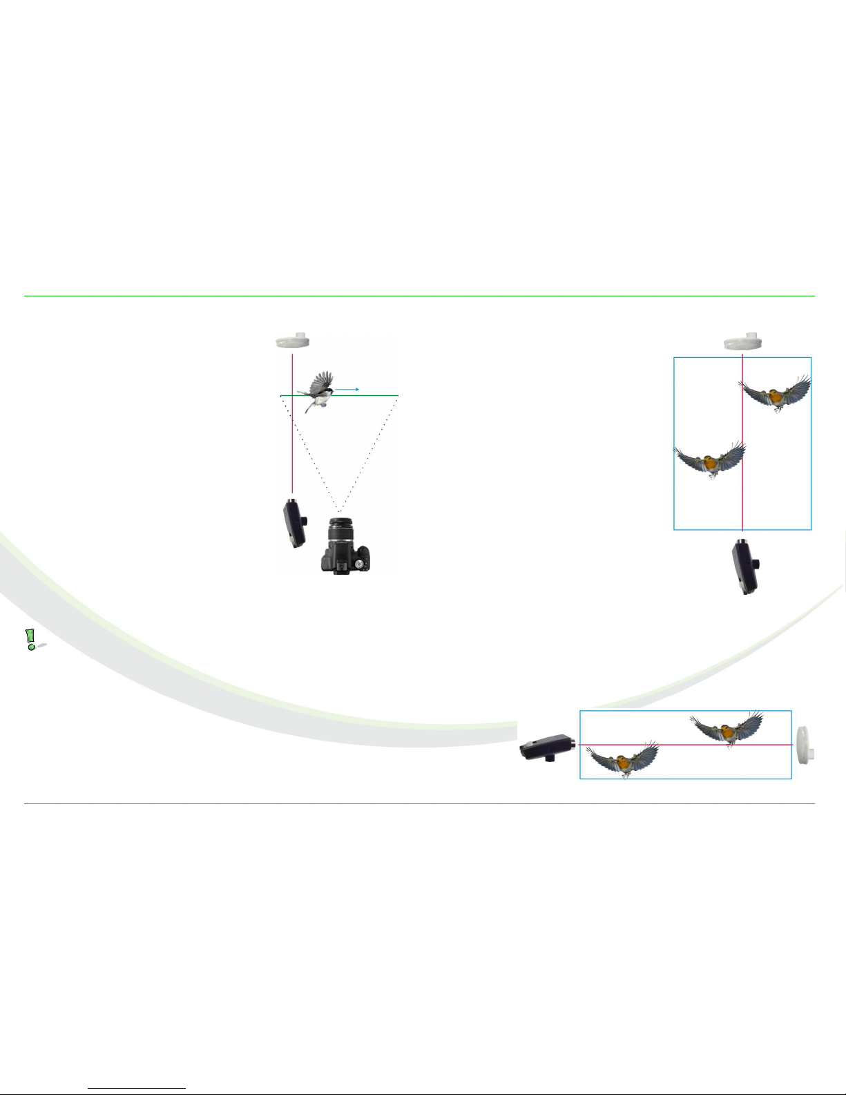
Using the geometry of the subject
The hit ratio will be highest when
the light beam is aligned in such
a way that it aims for the broad-
est side of the subject. This will
become clear in the following ex-
ample.
When looking at birds from the
front while they are flying, they
are way broader than they are
high.
If the light barrier is positioned
vertically, one can cover an area
(marked with a blue frame) that
is almost twice as broad as the
wingspread of the bird and as
high as the working distance,
with only one light beam, see im-
age 19.
When working with a horizontal
light beam the covered area is
drastically reduced because the bird can easily fly above or
below the beam, as shown in image 20.
20 © eltima electronic 2013
Image 18: Focal plane
parallel to flight path
Image 20: bird photography using a horizontal beam
Image 19: bird photography
using a vertical beam
Table of contents
Other eltima electronic Camera Accessories manuals


Popular Camera Accessories manuals by other brands

Panasonic
Panasonic ML614 Specifications

Manfrotto
Manfrotto MVR901ECEX user manual

Visceral Psyche Films
Visceral Psyche Films Leeming LUT Pro manual

Bosch
Bosch PowerPack 300 Series Original operating instructions

Panasonic
Panasonic WV-Q157 operating instructions

Ikan
Ikan PT4900-SDI-P2P-TK quick start guide


