eltima electronic joker2 User manual
1
Copyright eltima electronic 2020
Instruction manual
Light barrier system joker²
Version 12. 2020
From software version: 2.2.2.0
© Copyright eltima electronic 2020

2 Part Description
Copyright eltima electronic 2020
Part Description
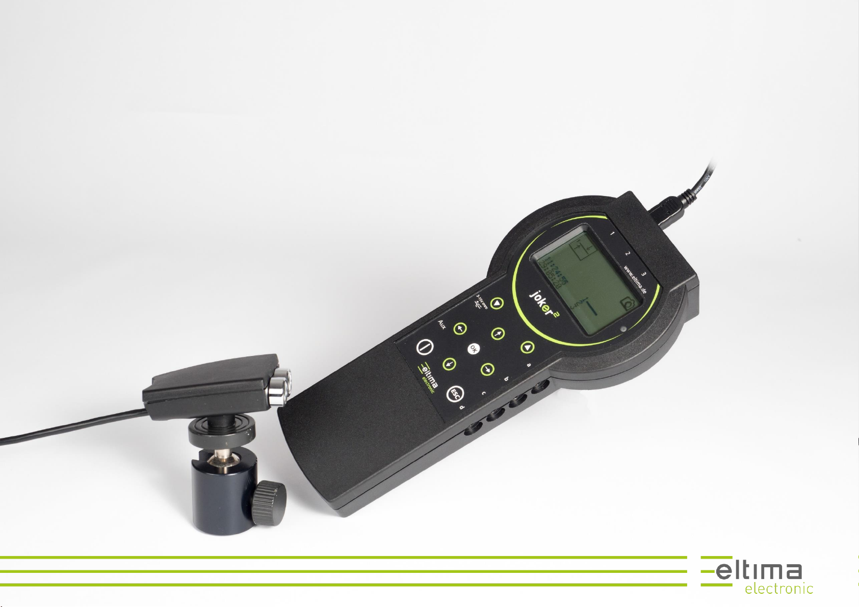
joker²controller
ON/OFF button
OK button
left button
level down button
control panel
display
light barrier plug
tripod thread
light barrier
receiver
IR-transmitter
tripod thread
light barrier plugs 1 - 3
DC plug aux plug
outputs a - d
battery case cover
battery case
ambient light sensor
level up button
up button
right button
down button
ESC button
3 Part Description
Copyright eltima electronic 2022
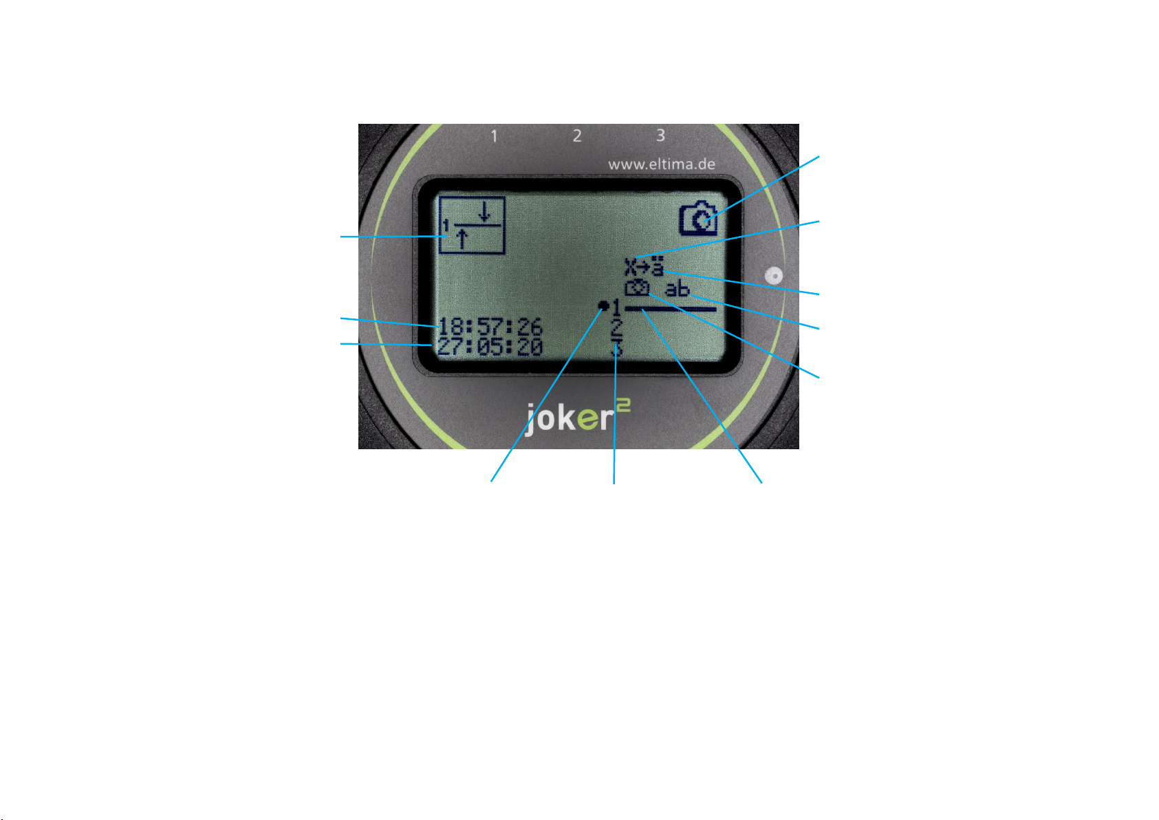
action mode icon
Date (dd:mm:yy)
time
light barrier interrupted
light barrier
reflection bar
one output is active
outputs a and b are active
switch a1 and a2 are active
step chain is active
level icon

4 Table of Contents
Copyright eltima electronic 2022
Table of Contents
Part Description........................................................................................ 2
Table of Contents...................................................................................... 4
Introduction.............................................................................................. 7
Symbols ......................................................................................................... 7
Purpose of use............................................................................................... 7
Maintenance and storage ............................................................................. 7
Quick start................................................................................................ 8
Inserting the batteries................................................................................... 8
Setting up the light barrier............................................................................ 8
Taking photos ................................................................................................ 9
Turning off the controller.............................................................................. 9
Operating concept of the joker² controller............................................... 10
Changing a parameter value ....................................................................... 11
Functional principle of the joker² light barrier system .............................. 12
The analog part............................................................................................ 12
The reflex barrier......................................................................................... 12
The light beam............................................................................................. 13
The reflectors .............................................................................................. 14
The action modes ........................................................................................ 15
The one beam barrier.................................................................................. 15
The cross barrier.......................................................................................... 16
The directional barrier .................................................................................16
The curtain barrier with two or three beams ..............................................17
The three beam cross barrier.......................................................................17
The directional cross barrier ........................................................................18
The time trigger............................................................................................18
The parameters of the action modes...........................................................19
Sensitivity 1 - 3.............................................................................................19
Range ...........................................................................................................20
Dwell Time ...................................................................................................20
Scanning mode.............................................................................................21
The digital part.............................................................................................22
The Outputs .................................................................................................22
Output parameters ......................................................................................22
Lag time........................................................................................................22
Release time.................................................................................................23
Release period..............................................................................................23
Interval.........................................................................................................24
Repetitions...................................................................................................24
Trigger ..........................................................................................................25
Drive mode...................................................................................................25
Wake-up.......................................................................................................26
Keep-active...................................................................................................26
Time window................................................................................................27

5 Table of Contents
Copyright eltima electronic 2022
Link .............................................................................................................. 27
The open-shutter mode .............................................................................. 28
Copy function .............................................................................................. 28
The levels for experimental photography................................................... 29
The Steps ..................................................................................................... 29
The X Parameters ........................................................................................ 31
Trigger.......................................................................................................... 31
Delay time.................................................................................................... 31
ON time ....................................................................................................... 32
Step duration............................................................................................... 32
Repetitions .................................................................................................. 33
Switch .......................................................................................................... 33
Next step ..................................................................................................... 34
Synchronization of step chains.................................................................... 35
The system functions................................................................................... 36
System parameters...................................................................................... 36
Date and time.............................................................................................. 36
Display lighting ............................................................................................ 36
Ambient light threshold .............................................................................. 37
Beeper ......................................................................................................... 37
Beeper loudness.......................................................................................... 37
Lag time measurement................................................................................ 38
Displaying the X-Parameters ....................................................................... 38
Speed measurement....................................................................................39
Unit for speed measurement.......................................................................39
Language......................................................................................................39
Resetting the parameters ............................................................................40
Reset to factory............................................................................................40
Software version:.........................................................................................40
Taking pictures with the joker² light barrier system ..................................41
Setup and alignment of the light barrier .....................................................41
Setup ............................................................................................................41
Alignment of the light barrier ......................................................................41
Improving the alignment of the reflector ....................................................42
Minimum distance to the reflector and sensitivity......................................42
The training process.....................................................................................42
Important camera settings...........................................................................43
Autofocus.....................................................................................................43
Speedlight, Flash ..........................................................................................43
Alignment of the light barrier to the camera and the subject.....................44
Plane of focus is parallel to the IR-beam .....................................................44
Plane of focus is parallel to the flight path ..................................................45
Taking advantage of the geometry of the subject.......................................45
Photographing without a reflector ..............................................................46
Programming examples ...........................................................................47
Taking pictures using the factory settings ...................................................48

6 Table of Contents
Copyright eltima electronic 2022
Operation principle of the factory settings:................................................ 48
Advanced example with a cross barrier ...................................................... 49
Process sequence: ....................................................................................... 51
Example for drop photography with X-parameters .................................... 53
Basic Parameters......................................................................................... 54
Output parameters...................................................................................... 54
X-Parameters............................................................................................... 54
Electrical connections.............................................................................. 55
Camera/device connection ......................................................................... 55
Power Supply............................................................................................... 55
Specifications.......................................................................................... 56
Type............................................................................................................. 56
Action Modes .............................................................................................. 56
Dimensions:................................................................................................. 56
Weight ......................................................................................................... 56
Power Supply............................................................................................... 56
Range........................................................................................................... 56
Smallest detectable object.......................................................................... 56
Shortest response time ............................................................................... 56
Scope of delivery ......................................................................................... 56
Disposal of electronical devices ............................................................... 57
Contact................................................................................................... 58

7 Introduction
Copyright eltima electronic 2022
Introduction
Dear Customer,
thank you for purchasing the joker²light barrier system. Developed and man-
ufactured with great care, it should be a reliable tool, handy and easy to use,
which leaves little to be desired.
If you have wishes and suggestions for improvement, please do not hesitate
to share them with us, so this product may grow to meet your needs.
Please read the instruction manual carefully before you use the light barrier
system. It will familiarize you with the operation and functioning of this sys-
tem. This way you can fully use the advantages offered by this system.
Symbols
Note symbol for tips on handling of the device.
Important note on the function of the device.
Important note to avoid damage to the device or the devices con-
nected to it.
Purpose of use
The light barrier system joker²is designed exclusively for triggering photo-
graphic equipment such as cameras, speedlights, filming devices, etc... Only
use it for this purpose! The improper use of the device can cause damage to
the light barrier system or the connected devices. In this case, the warranty
will be void.
Maintenance and storage
The light barrier system is not waterproof and is not suitable for use in
the rain or under water. If the device gets wet, contact the manufacturer.
Water drops can be wiped with a dry cloth.
Never drop the device and avoid rough impacts or vibrations.
This device is a precision electronic system. Do not attempt to make
changes by yourself.
If you plan to not use this device for a longer period of time, remove the
batteries from the battery case to avoid leakage.
Clean the lenses of the light barrier with a soft cloth from time to time.
8 Quick start
Copyright eltima electronic 2022
Quick start
A chapter for those in a hurry…
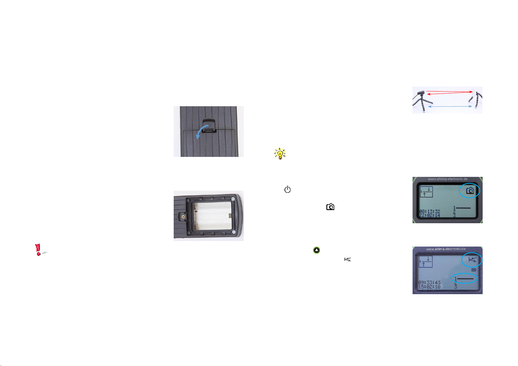
Inserting the batteries
Open the battery cover on the backside of
the controller, Figure 1.
Insert three cells of the type AA/LR6 in the
battery compartment. Put them into the
outer slots first, then into the middle one,
see Figure 2.
Please observe the polarity!
Close the battery cover.
Setting up the light barrier
Plug one of the light barriers into the plug 1.
Mount the light barrier and one reflector on a tripod each.
Place the light barrier and reflector opposite
to each other at a distance of about 1 m, see
Figure 3.
Note: This distance is arbitrary and is neither the smallest nor the
greatest distance between light barrier and reflector that can be
achieved.
Turn on the joker²controller by pressing the
button for at least 2 seconds. The display
will show the working level, see Figure 4,
marked by the icon.
Touch the button. The alignment level will
show, marked by the icon, see Figure 5.
Figure 1: Opening the bat-
tery cover
Figure 2: Inserting the bat-
teries
+
+
+
-
-
-
Figure 3: Setting up the
light barrier
Figure 4: Working level
Figure 5: Alignment level

9 Quick start
Copyright eltima electronic 2022
Now point the beam of the light barrier at the reflector. The length of the
reflection bar, Figure 5, indicates the degree of reflection coming from
the reflector. Adjust the light barrier horizontally and vertically until the
reflection is maximum, then tighten the barrier on the tripod.
Connect the camera with the adapter set to one of the outputs a to d of
the controller.
Place the camera with the image plane par-
allel to the light beam, see Figure 6.
Place a sharply contrasting object near the middle of the beam, turn on
your camera, and focus on the object.
Then set the autofocus on "manual" and remove the focus object.
Touch the button to return to the working level. With this step, the
light barrier is trained to the particular level of reflection when the beam
is not interrupted. The system is now ready. Interrupting the beam will
trigger the camera.
Taking photos
Let your subjects interrupt the light beam.
The optimal framing of the camera (Zoom level or distance from the
beam) and the plane of focus depend on the direction and speed of
your subject, as well as on the shutter lag of the camera. Adjust the
focus setting and the image frame after each shot, until you achieve
the desired result.
If you want to change the setup or the position of the light barrier, switch
again to the alignment level. Change the setup and switch back to the
working level
Turning off the controller
Briefly press the ON/OFF button.
Focal plane
Figure 6: Setting up the
camera
10 Operating concept of the joker² controller
Copyright eltima electronic 2022
Operating concept of the joker²controller
The controller is operated and set up through a number of “levels”, in which
the function of the system can be observed or parameters can be changed.
Each level is marked by an icon in the upper right corner of the display.
Except for the on/off button all control buttons are designed as touch sen-
sors (without tactile feedback).
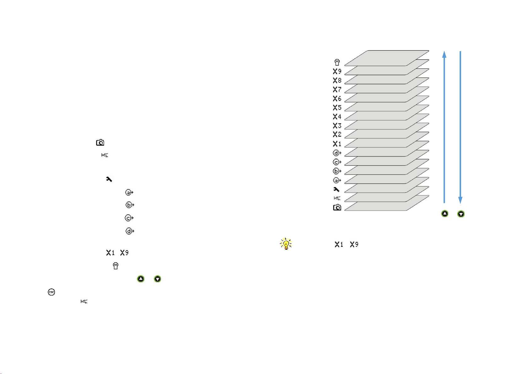
The following levels are available in the specified order:
Working and set-up levels:
Working level
Alignment level
Parameter levels:
Basic Parameters
Parameters for output a
Parameters for output b
Parameters for output c
Parameters for output d
Parameters for experimental photography,
steps, or X-levels -
System parameters
To move along the levels, touch the or key.
The key allows switching from any level, except the working level, to the
alignment level .
If the levels - for experimental photography are not needed
these can be hidden. To do this set the system parameter "Exp mode"
to "no", see Displaying the X-Parameters on page 38.
Figure 7: navigating through the levels

11 Operating concept of the joker² controller
Copyright eltima electronic 2022
Changing a parameter value
The basic procedure to change a parameter value is described for the param-
eters for output level a as an example.
To select a parameter, move the cursor up and down using the or
keys, see Figure 8.
Touch the button, the cursor will move to the parameter value. If the
parameter value is a multi-digit number, the cursor moves to the highest
digit. You can reach the desired digit of a number using the or key,
see Figure 9.
For some parameters the units can also be set (µs=microseconds,
ms=miliseconds, s=seconds or m=minutes). Use the key to get to
the units.
To change a digit or units touch the or key, see Figure 9.
To save the change, touch the button.
To discard the change, touch the button.
The action modes in the basic level are changed in the same way as other
parameters. Select the action mode parameter in the parameter level the
basic mode and touch the button. Change the action mode touching the
or button.
Figure 8: Selecting a parameter
Figure 9: Selecting a parameter
value
1
s
µs
9

12 Functional principle of the joker² light barrier system
Copyright eltima electronic 2022
Functional principle of the joker²light barrier system
Functionally, the light barrier system consists of an analog and a digital part.
The analog part controls and monitors the light barriers, the digital part con-
trols the outputs.
The analog part
The analog part controls and monitors up to the three light barriers con-
nected to the system. It captures their status and, if one has been inter-
rupted, it passes this information as a trigger to the digital part.
The reflex barrier
The light barriers of the joker²system are designed as reflex light barriers.
The transmitter and receiver are in the same housing.
The transmitter emits fast successive infrared light pulses, which are re-
flected by a reflector and sent back to the receiver. The strength of the re-
flection is shown by the reflection bar, see Figure 11.
If at least one pulse is missing, or is
received very weakly, e.g. because
an object is in the beam, the light
barrier is considered to be inter-
rupted. This status is reported as a
trigger to the digital part, which will
now control the outputs a to d. At
the same time, the interruption is in-
dicated with a dot next to the reflec-
tion bar, see Figure 12.
The subject itself can also serve as a
reflector. In this case, the light bar-
rier acts as a light sensor. This oper-
ating mode can be selected in the
basic parameter level. It can be set
individually for each of the three
light barriers. In this mode, how-
ever, the range is much smaller in
comparison with using a reflector.
The range essentially depends on
the reflective properties of the sub-
ject.
Figure 10: Reflex barrier
Figure 12: Light barrier interrupted
Figure 11: Reflexion bar

13 Functional principle of the joker² light barrier system
Copyright eltima electronic 2022
The light beam
As described, the light barrier emits fast successive invisible infrared light
pulses (one pulse of 10 µs each 200 µs), which are sent back by a reflector to
the receiver. The receiver needs to receive back a certain amount of the emit-
ted light of each pulse. This amount of light is determined during the training
process, see section The training process. If it changes by a measure that was
defined with the sensitivity parameter, the light barrier is considered to
be interrupted and a trigger is reported to the digital part.
Due to the characteristics of the optical components, combined with the re-
flective properties of the retro reflectors the beam path is fairly complex.
However, in a simplified way, it can be explained as follows:
The path between the light barrier and reflector, hereinafter called working
distance, can be roughly divided into three sections.
The middle section marked green is the "normal" working section of the light
barrier. Depending on the reflector and the selected working distance the
effective "beam diameter” is about 2 - 5 mm. An object must cross this beam
in order to trigger the light barrier. This small diameter leads to a very precise
and reproducible switching point of the light barrier.
In the orange section, close to the reflector, the sensitivity decreases and
small objects will no longer be reliably detected because light may be re-
flected around the object.
In the blue area near the light barrier, the outgoing beam from the transmit-
ter, and the reflected beam coming to the receiver are farther apart, result-
ing in a more complex pattern, and less predictability as to where an object
might trigger the light barrier.
In the green area, the two beams are so close together they can be con-
sidered as a single beam.
As a result, the system should optimally be set up so that the subjects will
cross the light beams in the green area, which is roughly the middle one third
to two thirds of the working area.
Figure 13: Sections of the light beam
14 Functional principle of the joker² light barrier system
Copyright eltima electronic 2022
The reflectors
The scope of delivery of the joker²light barrier system includes three 8 cm
retro-reflectors. They consist of a circular plate with many honeycomb cor-
ner reflectors.
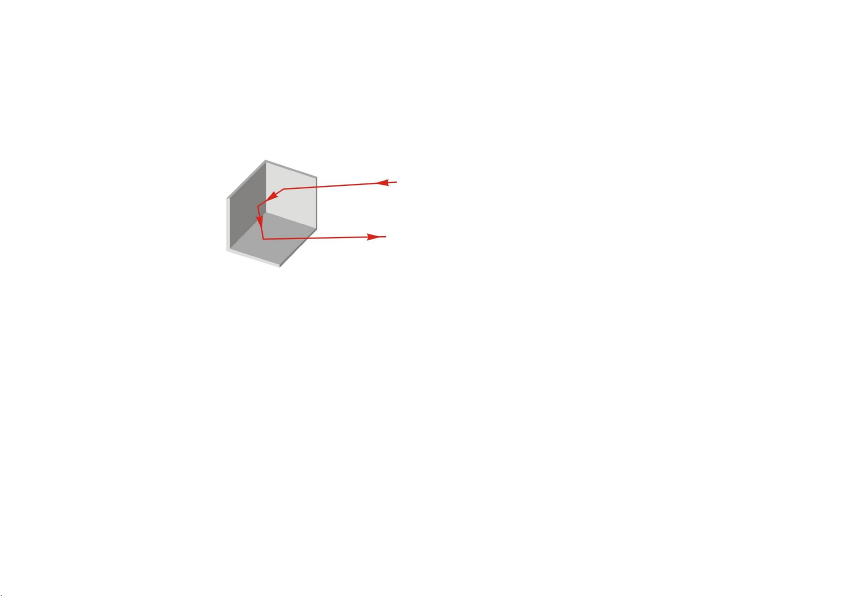
Corner reflectors have the prop-
erty that they reflect light back to
its source with a minimum of off-
set. Figure 14 shows the operating
principle of a corner reflector.
Due to this property a retro reflec-
tor, in comparison to a mirror, does
not need to be aligned exactly to-
wards the light barrier. It is suffi-
cient to be aligned roughly towards
the light barrier. Only for reaching
the maximum working distance
does the reflector need to be aligned exactly.
Figure 14: Corner reflector

15 Functional principle of the joker² light barrier system
Copyright eltima electronic 2022
The action modes
The joker²light barrier system offers the possibility to combine the three
light barriers in different ways. Such a combination within this light barrier
system we call an "action" mode.
Certain states of the light barriers involved are assigned to each action mode.
As soon as these states become ‘true’, the action mode is considered to be
met. This status is then reported to the digital part as a trigger for an action.
Each action mode is represented by a pictogram. In these pictograms, the
numbers 1 to 3 indicate the light barriers involved.
A parameter set is saved for each action mode, which determines the optical
and timing behaviour of the light barriers.
The one beam barrier
Symbol: , Level:
The one beam barrier consists of the beam of the light barrier 1. If this is
interrupted, the action mode is met.
After the action mode is met, the light barrier must first be reset (the obsta-
cle mist move from the beam) before a new action can be triggered.

16 Functional principle of the joker² light barrier system
Copyright eltima electronic 2022
The cross barrier
Symbol: , Level:
In order to increase the selectivity, the cross barrier can be used. It is formed
by the light barriers 1 and 2, which are linked by a logical AND. This means
that the action mode is met if both light barriers are interrupted at the same
time (1 AND 2).
The light beams are typically ar-
ranged crosswise and in one plane.
The action mode is met, when the
subject interrupts both light barriers
at the crossing point. Thus it is possi-
ble to have more precision on the
subject location and arrange the ar-
tistic composition of a picture
The point or rather the "sensitive"
area in which the action mode can be
met depends on both the size of the
subject and the angle that the two
beams form. If the light beams cross
at an angle of 90°, the area is the
smallest. Furthermore, the larger the
subject, the larger the sensitive area.
However, the light beams do not necessarily have to be arranged crosswise
in one plane. They can be arranged anywhere in space. The action mode will
be met when both light beams are interrupted at the same time.
Once the action mode is met, both beams must be reset before a new action
can be triggered.
The directional barrier
Symbol: , Level:
The directional barrier is formed by the light barriers 1 and 2. The action
mode is met if at first the light barrier 1 and subsequently the light barrier 2
is interrupted.
When light barrier 1 is interrupted, the system is activated and waits for light
barrier 2 to be interrupted. If this happens, the action mode is deemed to be
met and the status is reported to the digital part as a trigger.
If an object first moves through light barrier 2 and then through 1, i.e. in the
opposite direction, no trigger is issued.
Once the action mode is met, both beams must be reset before a new action
can be triggered.
When setting up the direction barrier, care must be taken to ensure
that the objects move through both beams. If an object only inter-
rupts light barrier 1 and not light barrier 2 (e.g. because it stops or
changes direction) the system will still be activated. If an object then
comes from the "wrong" direction, i.e. from 2 to 1, the action mode
will be met and the trigger set when light barrier 2 is interrupted. If
the object continues to move and now also interrupts light barrier 1,
the system will be reactivated. So the direction becomed reversed!
To get back to the initial direction an object must cross the barriers
from 1 → 2.
Subjects
Light beams
Sensitive area
17 Functional principle of the joker² light barrier system
Copyright eltima electronic 2022
The curtain barrier with two or three beams
Symbols: or , level:
To increase the detection rate, a curtain barrier can be used. In this mode,
the system effectively scans an area formed by two or three light beams. The
light barriers are linked by a logical
OR. This means that the action
mode is met, any one of the light
barriers is interrupted.
Usually the participating light barri-
ers would be set up parallel in a
plane (to make the position of the
subject more predictable), but they
could be set up facing any direction.
In this mode, any beam that is inter-
rupted must be reset before a new
action can be triggered even by a
different beam.
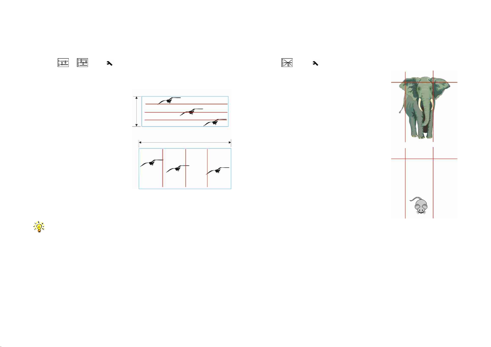
Note: Depending on the application, it can be advantageous to set up
the light barriers vertically, as in the example in Figure 15. In this case
the wide wingspan of the bird allows the beams to be placed farther
apart, increasing the area of detection (blue rectangle). In the hori-
zontal arrangement the birds present a narrower target, so the beams
must be closer together and the active area is much smaller.
The three beam cross barrier
Symbol: , Level:
Just like the simple cross barrier, the three beams
barrier increases the selectivity of the system.
The light barriers are linked by a logically AND.
The action mode is met when all three light bar-
riers are interrupted at the same time, at which
point the trigger will be passed on to the digital
part.
The light barriers do not need to cross in one
point.
For example in the setup in Figure 16, the large
animal is detected, because it interrupts all three
light barriers, but the small is not because it could
only interrupt at most one barrier.
Once the action is met, all three beams must be
reset before a new action can be triggered.
Figure 15: Curtain barrier
Figure 16: Blanking out of
small objects

18 Functional principle of the joker² light barrier system
Copyright eltima electronic 2022
The directional cross barrier
Symbol: , Level:
The directional cross barrier is a combination of a directional and a cross bar-
rier. The action mode is met if at first the light barrier 1 and subsequently the
cross barrier formed by 2 and 3 is interrupted.
When light barrier 1 is interrupted, the system is activated and waits for the
cross barrier to be interrupted. Once this happens, the action mode is
deemed to be met and the trigger is passed on to the digital part. As with the
simple directional barrier, the action may not work as predicted if an animal
interrupts barrier 1, but then does not pass the cross barrier.
Once the action mode is met, all three light barriers must be reset before the
system is ready for the next sequence.
The time trigger
Symbol: , Level:
Time-scheduled recordings can be made with the time trigger. For this a start
time, an end time and a programmable trigger period are available. The ac-
tion mode shall be deemed to be met, if the start time is reached and subse-
quently whenever the programmed period has expired until the end time is
reached. This mode can be used for time lapse photography, for example.
For this action mode no light barriers are needed.

19 Functional principle of the joker² light barrier system
Copyright eltima electronic 2022
The parameters of the action modes
Each action mode has several parameters that determine their behaviour.
Once they are changed, they are saved together with the respective action
mode, and will be remembered even if the system is turned off.
Sensitivity 1 - 3
Name
Default setting
Range
Level
sensit 1
6
1 - 9
sensit 2
6
1 - 9
sensit 3
6
1 - 9
The optical sensitivity of each individual light barrier can be set with this pa-
rameter. The value 1 represents the highest sensitivity, 9 the lowest. The
smaller the value, the more sensitive the barrier will be to a small change in
reflectance, allowing smaller objects to be detected. The larger the value, the
less sensitive the barrier, and the larger an object must be.
In the case of working without a reflector, the parameter determines the
minimum amount of light that must be reflected by the subject to set a trig-
ger.
This parameter can be used, for example, to blank out small objects
in favour of large ones. For example, when photographing mammals
larger values should be set so there will be no false triggering due to
small objects such as insects passing by.
Select the sensitivity as low as possible (the number should be as large
as possible). The higher the sensitivity (lower the number), the more
challenging the requirements are for the setup of the light barriers
and reflectors. They must be very stable to minimize the risk of false
triggers. If the sensitivity is at its highest level (i.e., 1), even slight vi-
brations or shocks can change the reflection enough to lead to un-
wanted triggers.
20 Functional principle of the joker² light barrier system
Copyright eltima electronic 2022
Range
Name
Default setting
Range
Level
Range
distance
sensitive/
distance
The range parameter controls the power of light the infrared transmitter
emits per pulse. The quantity of light affects both the range and the sensitiv-
ity of the light barriers.
The "normal" working range is distance. With this setting a range of ap-
prox. 10 m between the light barrier and the reflector can be achieved. The
sensitivity is enough to photograph also small subjects like insects. With the
setting sensitive the light barrier can react to objects down to 0.5 mm.
When photographing of very small objects at working distances less
than 60 cm we recommend the use of 40 mm reflectors (not included
in the scope of delivery).
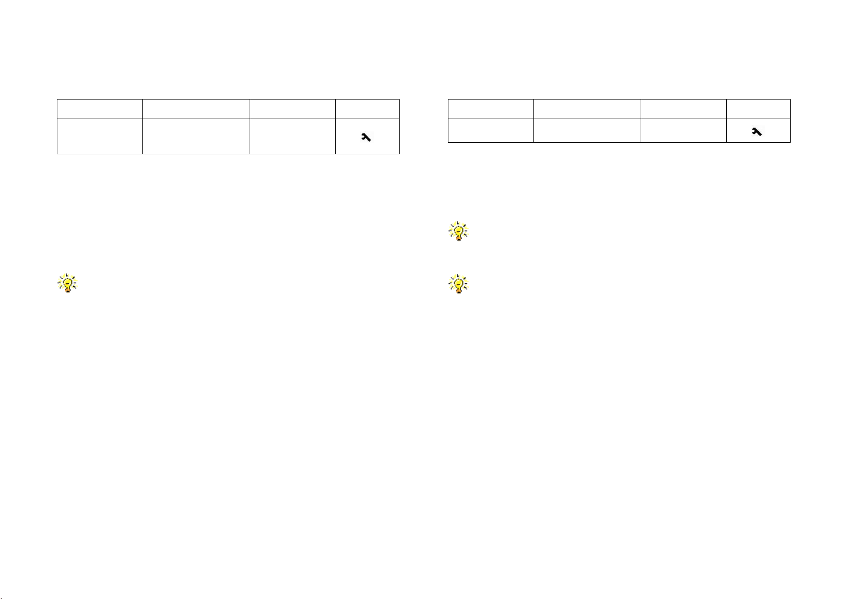
Dwell Time
Name
Default setting
Range
Level
dwelltim
0000
0 ms - 60
minutes
The dwell time determines the time an object must stay in the beam of
the light barrier to be considered interrupted.
Using this parameter, fast moving objects can be blanked out in favour of
slow ones.
For example, a longer res time can be used to prevent rain drops,
snowflakes or insects buzzing around from causing unwanted triggers
when photographing mammals.
Wherever a fast response time is important, this parameter should be
set to 0 (the default).
Table of contents
Other eltima electronic Camera Accessories manuals


Popular Camera Accessories manuals by other brands

Continental Refrigerator
Continental Refrigerator AGM installation guide

Ozito
Ozito PXBP-200 instruction manual

Bioenno Power
Bioenno Power BLF-1206W user manual

Fantasea
Fantasea CP-6 instruction manual

Multiplex
Multiplex MULTIGYRO CSX 1-00092 installation instructions

Green Rhino
Green Rhino CRYSTAL 6-GREV-180 user manual


