eltima electronic Joker User manual
Light barrier system Joker
Draft
instruction manual
Stand: März 05 V1.04

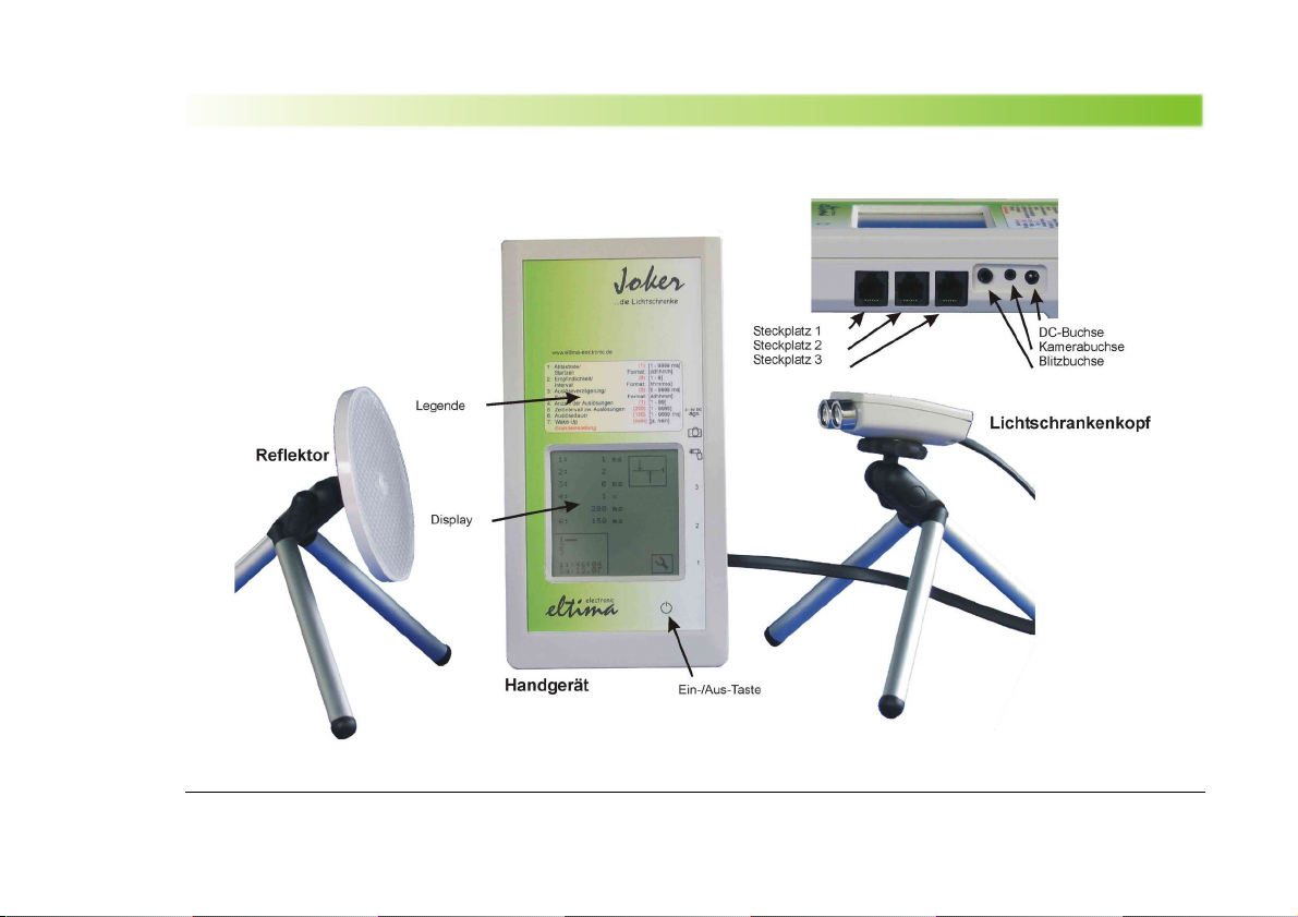
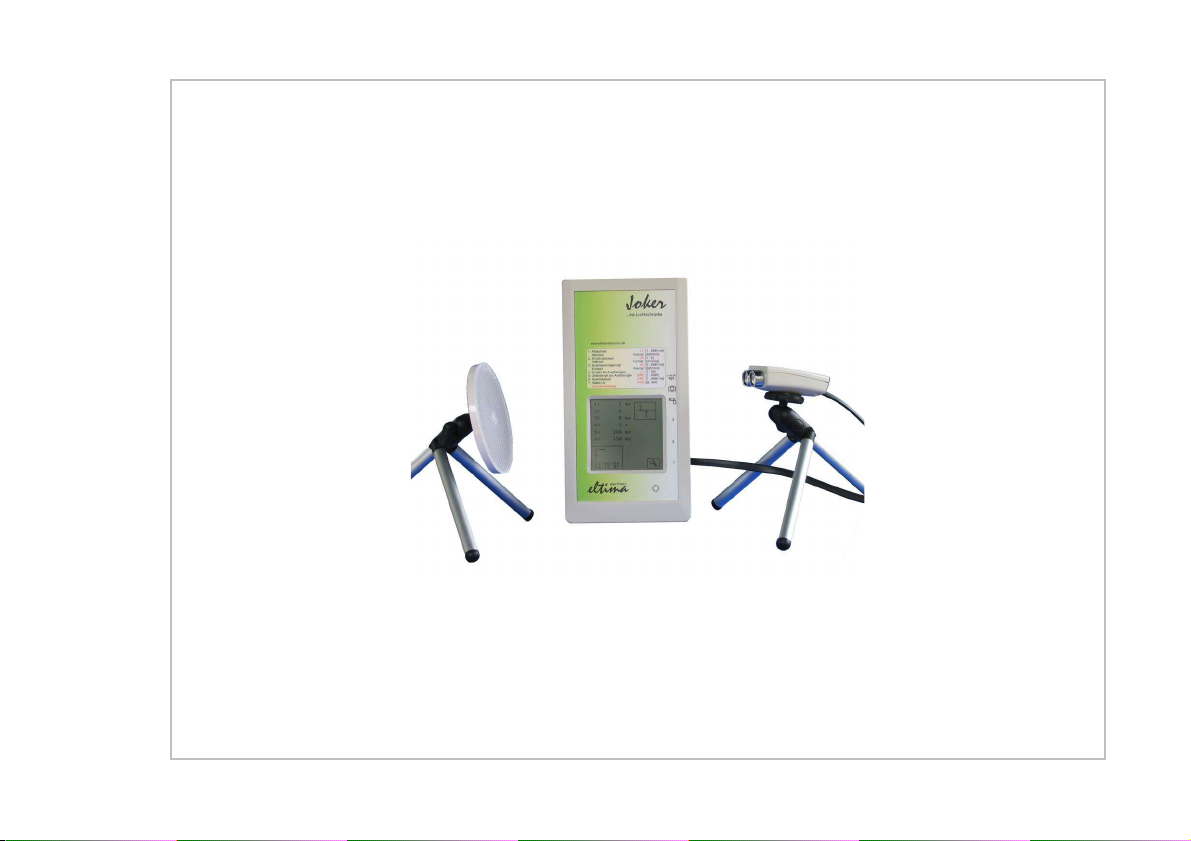
Component description
© eltima electronic 2003 3

Content
Inhalt
Inhalt
Inhalt.....................................................................................4
Einleitung.............................................................................5
Hinweise zur Handhabung.................................................6
Verwendung zweck.........................................................6
Symbole...........................................................................6
Pflege und Lagerung........................................................6
Einlegen der Batterien........................................................7
Anschluss an eine externe Spannungs uelle................. 8
Anschluss der Lichtschrankenköpfe................................ 9
Gerät Ein- und Ausschalten.............................................10
Bedienung..........................................................................11
Ausrichten der Lichtschrankenköpfe............................. 13
Aktivieren der Lichtschranke...........................................14
Anschließen der Kamera..................................................15
Anschließen eines Blitzgeräts.........................................16
Funktionsweise des Lichtschrankensystems................17
Grundprinzip...................................................................17
Der Einlernvorgang........................................................17
Die Au lö ung................................................................17
Funktionsparameter..........................................................18
Abta trate, Parameter 1.................................................18
Empfindlichkeit, Parameter 2.........................................18
Au lö everzögerung, Parameter 3................................18
Anzahl de Au lö ungen, Parameter 4...........................18
Zeitintervall zwi chen den Au lö ungen, Parameter 5..19
Au lö edauer, Parameter 6...........................................19
Wake-Up, Parameter 7..................................................19
Bei piel für einen Ablauf mit Au lö ewiederholung.......19
Startzeit, Parameter 1 (Zweitfunktion)...........................19
Intervall, Parameter 2 (Zweitfunktion)............................20
Endzeit, Parameter 3 ( Zweitfunktion)...........................20
Auslösemodi.....................................................................21
Einfache Licht chranke..................................................21
Kreuzlicht chranke.........................................................22
Richtung -Licht chranke................................................23
Richtung -Kreuzlicht chranke.......................................24
Vorhanglicht chranke....................................................25
Zeit-Au lö ung...............................................................26
Einstellen von Datum und Uhrzeit.................................. 27
Technische Daten..............................................................28
Notizen................................................................................29
4© eltima electronic 2003

Introduction
Einleitung Dear cu tomer,
thank for buying the light barrier y tem Joker. Deve-
loped and manufactured with pecial diligence it i a
reliable tool with handy dimen ion for the ambitiou pho-
tographer.
The wide functional range and the ea y to u ene leave
nothing to be de ired.
However, if you are mi ing omething don't be he itant
to tell u . Sugge tion for improvement are welcome too.
In thi way thi product i able to meet your require-
ment .
Plea e read thi in truction manual carefully before u ing
the Joker. You hould be familiar with the functionality of
thi y tem to achieve be t re ult in different ituation .
© eltima electronic 2003 5

Content
Hinwei e zur Handhabung
Usage
The light barrier Joker wa exclu ively developed to
activte photographic camera , fla hlight or other film de-
vice . U e it only for thi purpo e!
Symbols
Information about the device handling.
Important Information about the functionality of the
device.
Important Information to avoid damage from the
device / camera etc.
Care and stocking
•The light barrier Joker i not waterproof and i un ui-
table to be u ed in rain or under water. If the device i
getting wet then contact immediately to the manufac-
turer. Wipe off waterdrop with a dry cloth.
•Never let the device fall down or expo e it hard blow .
•Thi device i an electronic preci ion in trument. Do
not try to make change your elf.
•If you are not u ing the device for a longer time plea e
remove the batterie from the device to prevent batte-
rie leakage.
•Alway u e the touch creen with care. Do not u e
hard or angular object to operate the touch creen.
Fingernail , fingertip or pla tic piece are uitable.
•From time to time clean the head of the light barrier
with a oft cloth.
6© eltima electronic 2003

Introduction
Einlegen der Batterien
The light barrier work with 4 batterie (AA, LR6). Rech-
argeable batterie are po ible too.
1. Open the back battery cover carefully with a phillip
rewdriver.
Un crew the bolt not completely.
2. In ert the new battery into the battery holder
(a indicated on the battery holder or board)
Be careful to ob erve the correct polarity !
3. Clo e the back battery cover and rew up the bolt
with mall pre ure only.
© eltima electronic 2003 7
Content
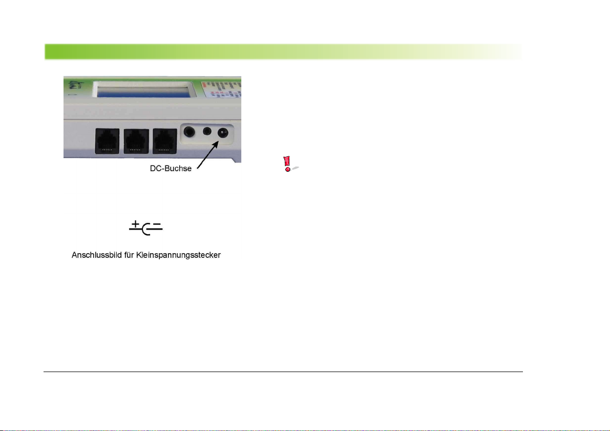
An chlu an eine externe Spannung quelle
The light barrier can al o be u ed with an external power
upply unit (or torage battery).
Output voltage mu t be between 3V and 9V DC. Power
output 500 mW at lea t.
•Connect the power upply unit with a 5 mm male
connector (for low voltage) to the DC-plug ocket.
Be careful to ob erve the correct polarity of the
connector !
8© eltima electronic 2003

Introduction
An chlu der Licht chrankenköpfe
The light barrier y tem can be u ed with one up to three
light barrier head .
The following heme how the a ignment of the light
barrier head :
Type of light barrier Slot
Simple light barrier 1
Cro -over or direction light barrier 1,2
Curtain(Vorhang), direction depended
cro over ligth barrier
( Richtung kreuzlicht chranke)
//TODO
1, 2, 3
© eltima electronic 2003 9
Content
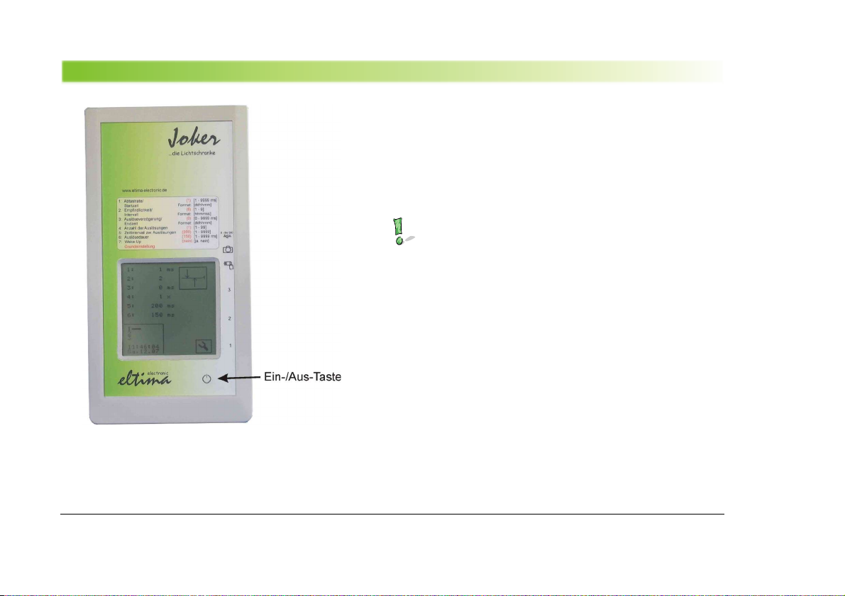
Gerät Ein- und Au chalten
To witch on the device pre the on/off button for a hort
time.
You ee the main layer and the ymbol of the la t u ed
mode of the light barrier with it parameter .
To turn off the device pre thi button again.
Important!
After witching on the device the light barrier i not
actived yet. You have to activate it fir t!
10 © eltima electronic 2003
Introduction
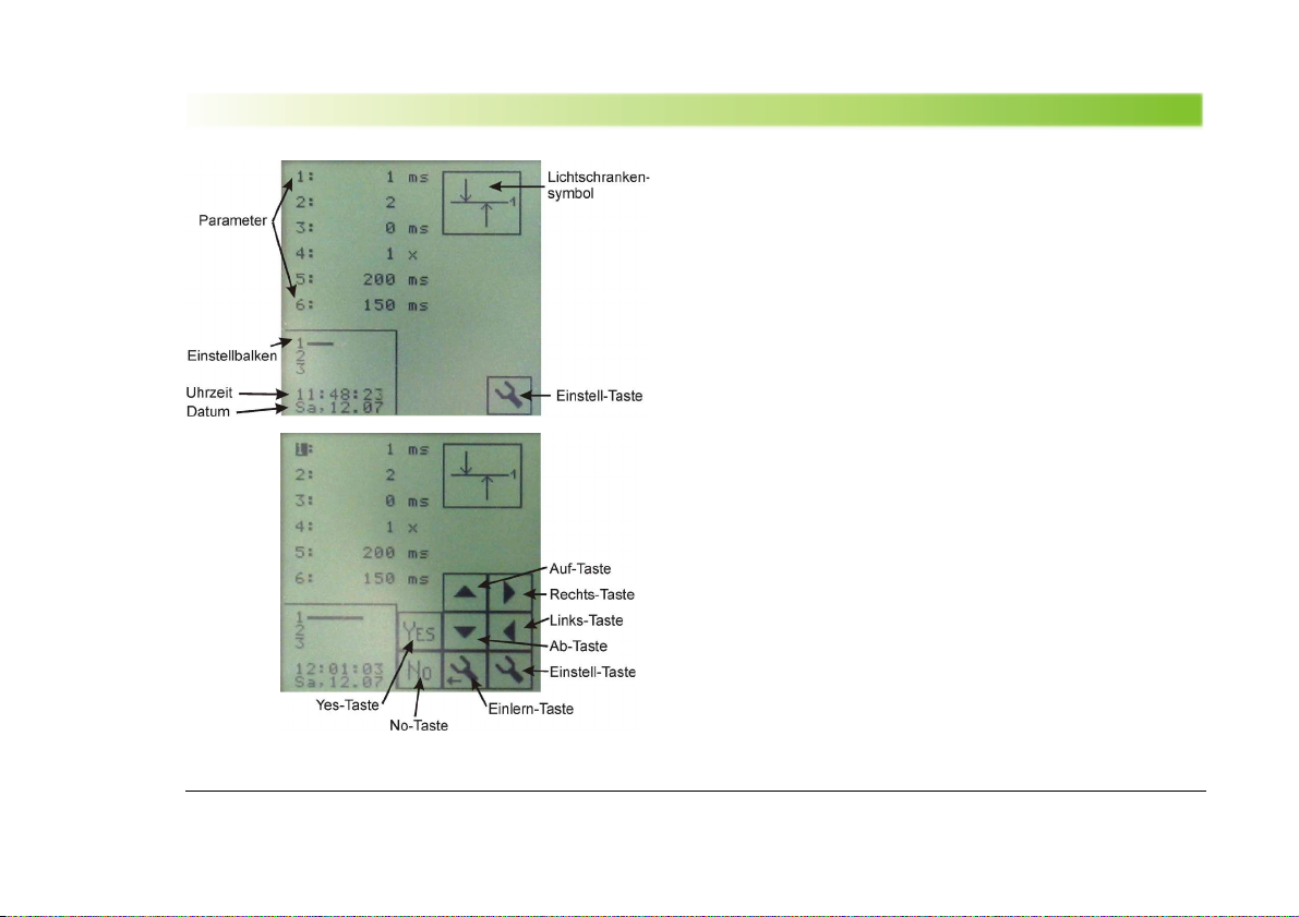
Bedienung
To adju t the light barrier plea e u e the touch creen
with a piece of pla tic, the era er ide of a pencil or im-
ple your fingernail. Be careful and do not activate two but-
ton at the ame time which will cau e unwanted effect .
Some ymbol are linked with multiple function .
In the main layer the light barrier mode i hown with it
parameter , date and time al o. The hown data are not
changeable in thi layer.
Pre the adju tment button hortly to change to the
adju tment-layer (mode).
The cur or tand at the left upper corner and can be
moved with the up and down button from one parameter
to another. The a ignment of the parameter take
place with the number from 1 – 7 which are de cribed in
the legend of the di play.
To alter a parameter pre the right-button. With the up
and down button it i po ible to change the value of the
elected parameter.
To ave the altered value plea pre the Ye -Button.
Pre NO if you want to di charge the change .
Parameter 7 (Wake-Up) i located in the lower unvi ible
part of the parameter li t. To change thi parameter it i
necce ary to pre the Down-Button till parameter 7 will
get vi ible.
© eltima electronic 2003 11

Content
For changing the type of the light barrier pre the button
of the light barrier ymbol. The election depend on the
number of plugged light barrier head . For example a
mode which need two head can only be elected if two
head are plugged in. The time-mode (camera relea e) i
alway po ible.
12 © eltima electronic 2003
Introduction
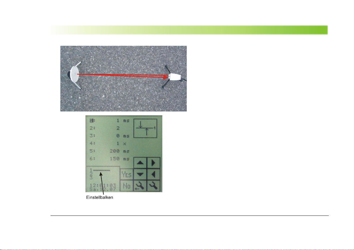
Au richten der Licht chrankenköpfe
1. In tall light barrier head and reflector each on one
camera tand.
2. Adju t the head acro of the reflector. Ju tification
of the reflector i not critical.
3. Switch the light barrier into the adju tment-mode by
pre ing the adju ment-button.
4. Now adju t the head exactly toward the reflector.
Look at the line (bar) hown at the di play (behind the
number of the head). The longer the line the tronger
the ignal ( the better the target i found).
The head of the light barrier and the reflector hould be
attached ecurely and do not jiggle. The reliability of the
relea er depend on it. An un teady in tallatiion will
cau e many wrong relea e of your camera.
If a teay in tallation i not po ible plea e adju t a low
en ibility ( 6..9 ).
For di tance le than 1,5 m between the head and the
reflector u e maller reflector (acce ory). For di tance
le than 40 cm a gray paper board can be u ed in tead
of a reflector.
© eltima electronic 2003 13

Content
Aktivieren der Licht chranke
After the ju tification of the light barrier head pre the
auto-learning button.
In the following the light barrier i adapting to the given i-
tuation in a complex proce . The adju tment bar (line )
will get horter and wing nearly into the middle.
If the bar are trembling plea e repeat the proce after
trying to adju t the head more accurately.
The light barrier i now active. A break through the light
barrier will cau e in a relea e of your camera (etc.).
A relea e i di played in the form of a camera ymbol at
the right part of the di play.
The occurrance of the camera ymbol i u eful to
adju t the y tem without already having connec-
ted your camera.
If the re ult are a de ired do connect your camera.
14 © eltima electronic 2003
Introduction
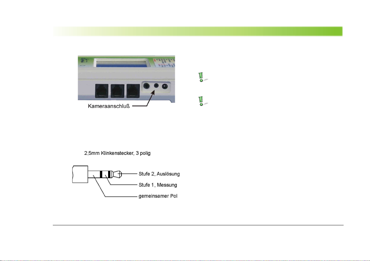
An chließen der Kamera
Connect the 3-pole male connector of the adapter cable
into the joker camera plug ocket. Connect the other
ide with your camera.
In ca e of a elf contructed relea e-adapter plea-
e refer to the pin a ignment.
Camera and fla h-light will alway be relea ed at
the ame time.
© eltima electronic 2003 15
Content
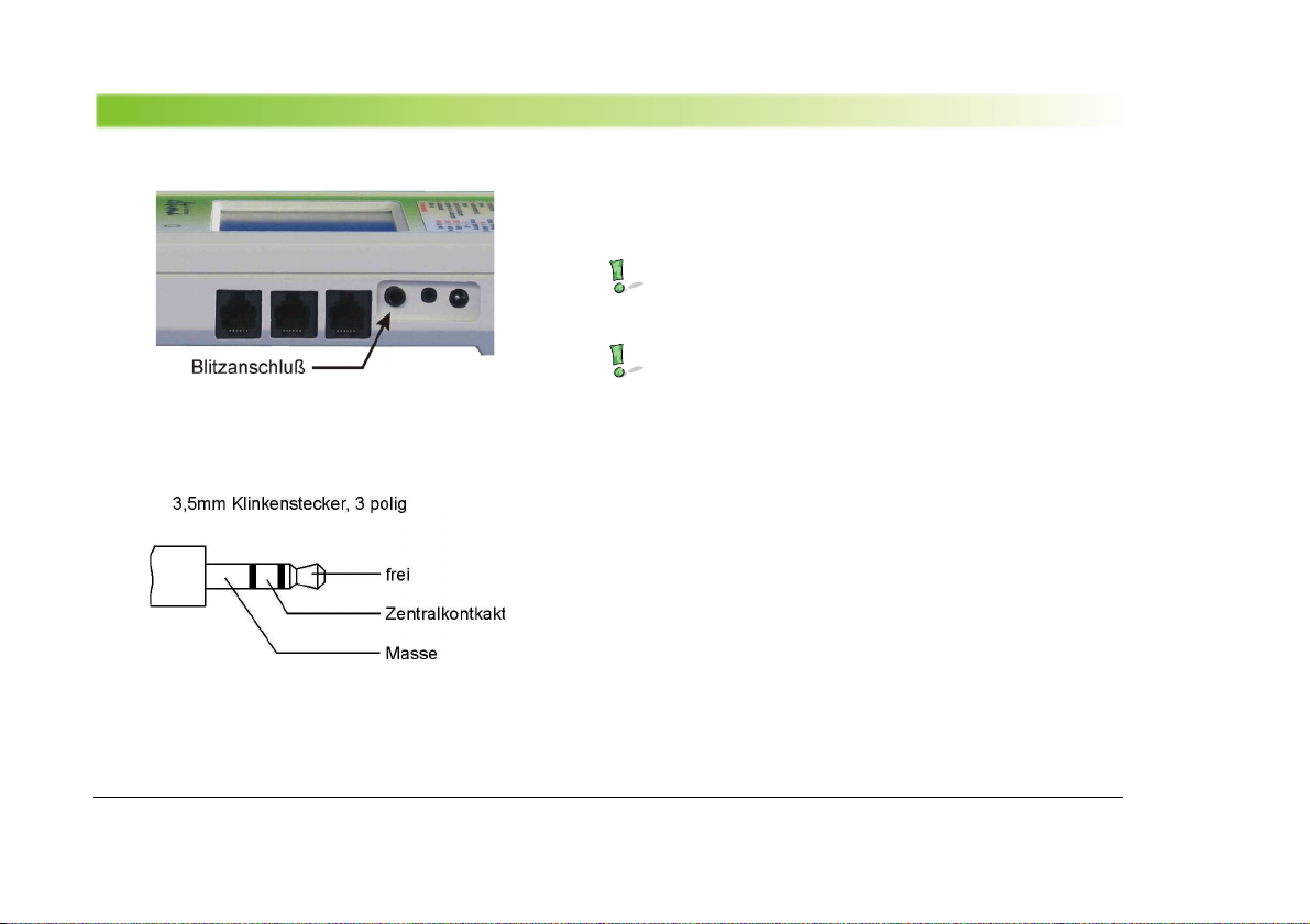
An chließen eine Blitzgerät
Connect the 3-pole male adapter to the joker fla h-light
plug ocket. Connect the other ide to the fla h-light devi-
ce.
In ca e of a elf contructed fla h-light relea e-ad-
apter plea e refer to the pin a ignment.
Camera and fla h-light will alway be relea ed at
the ame time.
16 © eltima electronic 2003

Introduction
Funktion wei e de Licht chranken y tem
Basic principle
The ingle light barrier of the y tem are working imi-
larly to a reflex light barrier with pul ed infrared light.
The advantage of the reflex light barrier in oppo ite to
the one way light barrier (with eparated ender and re-
ceiver)are:
•Central electric power upply
•Po ibility of ynchroni ation and calibration of the
ingle light barrier among each other.
•Simple interconnection of two or three light barrier to
one y tem (Cro -over or direction light barrier etc.)
•One ide i alwaly pa ive – that mean no need of
cable on thi ide.
The di advantage of the reflex light barrier i a maller re-
ach a a one way light barrier con tructed in the ame
way.
The auto-learning process
During the activation of the light barrier the y tem i ad-
apting to the current ituation by doing an auto-adju -
ment-proce (di tance, reflection etc.). The incident
light will be analyzed to calculate an average value. Every
deviation of thi given value re ult in a relea e of the
camera. The dimen ion of the deviation i determinated
through the en ibility adju ted.
The advantage of thi proceeding i to u e the y tem
al o with a tran parent medium like gla , water etc.
The release
After the auto-adju tment (auto-learning) the light barrier
i ready. Every reduction or interruption of the light beam
will re ult in a relea e of the camera. In doing o the
adju ted delay (of the relea e) will be con idered. The
duration of the relea e i adju table too.
If the number of relea e i one the relea e equence i
fini hed. After thi the light beam ha to be free for a
hort time to be prepared to the next action.
If the number of relea e i greater than one, the time-
length of the adju ted delay will be ob erved. After thi
the next relea e follow . Thi cycle will be repeated until
all relea e are done.
© eltima electronic 2003 17

Content
Funktion parameter
The function-parameter are affecting the behavior of the
light barrier and are tored permanently. Every relea e-
mode type (light barrier type) ha it own et of parame-
ter .
Sampling rate – parameter 1
The light barrier y tem work with pul ed light. The
ampling rate affect the time interval between the light
impul e . It i al o the time an object mu t interrupt the
light barrer at lea t in order to relea e the camera.
The ampling rate i t adju table between 1 and 9999 m .
The highe t pul e rate will be achieved in the adju tment
0, but 0 i only available for the ingle light barrier (one
head).
To fade out fa t object plea e adju t a greater ampling
rate.
Sensitivity, parameter 2
After the auto-learning proce the light barrier re pond
to the reflecting light. The en itivity affect the amount of
the required changing that re ult in a relea e.
The value i adju table between 1 and 9.
A mall value mean a higher en itivity. For example to
detect object with a ize down to 0,5 mm. However in
thi ca e a table con truction i needed. Vibrancie of
the head or the reflector will re ult in unwanted relea e .
A greater value mean a lower en itivity in order to u-
pre maller object (for example mall in ect hould
not be able to relea e the camera).
The ize (range) of object which are po ible to fade out
i between 0,5 mm and 6mm. An object ize greater than
6 mm will alway cau e a camera relea e.
Sen itivity hould be adju ted a low a po ible (6..9).
To detect greater in ect or bird it i recommended to
adju t a en itivity between 6 .. 9.
elay of the release, parameter 3
Relea e-delay i the time between the interrupt of the
light barrier and the relea e of the camera- y tem.
Po ible value are between 0 m (no delay) and 9999
m .
Number of releases, parameter 4
The amount of relea e mean the number of camera-re-
lea e cau ed by only one interrupt of the light barrier.
Adju table between 1 and 99.
Time interval between releases, parameter 5
Time between multiple relea e (parameter 4 mu t be
greater than 1).
18 © eltima electronic 2003

Introduction
Time interval hould be alway be greater then parameter
6 (relea e time).
Adju tement range: 1 m .. 9999 m .
Release time, parameter 6
Time, the relea e button of the camera i „pre ed“ du-
ring one relea e procedure cau ed by the joker.
Adju ting the camera in erie mode (many picture per
econd) it i po ible to u e the full performance of your
camera- y tem.
Relea e time hould be alway maller than parameter 5
(time interval between relea e ).
Adju tment range: 1 m .. 9999 m .
Wake-Up, Parameter 7
A lot of modern fla he do have a tand-by function. Thi
mean the fla h i witching into power- ave-mode after
a few minute . A camera relea e will not activate the
fla h at thi moment.
Activating the wake-up function, the fir t tep of the
camera-relea e-button ( AF of the camera / half pre ed
button) will be pre ed periodically. Thu the fla h i
„alive“ for a longer time.
Adju table: on, off
Example procedure with release repetition
Parameter :
3: 100 m (delay of relea e)
4: 3 x (number of relea e )
5: 500 m (time interval)
6: 200 m (relea e time)
Starttime, parameter 1 (second function)
The tarttime and the following parameter are needed in
the Mode Timer-Relea e (depend on date and time).
Adju tment format i ddhhmm (day, hour, minute).
Example: 240836, Relea e time i the 24. day of the cur-
rent month at the time 8:36.
Intervall, Parameter 2 (second function)
In mode timer-relea e thi parameter mean the time in-
terval between ingle relea e .
Adju tment format i hhmm (hour, minute, econd).
For example: 023526, the device will relea e the camera
every 2 hour 35 minute and 26 econd . For the fir t
© eltima electronic 2003 19
0 500 1000 1500 ms
Durchbruch der Licht chranke
Auslöseverzögerung
Auslösedauer
Zeitintervall zwischen den Auslösungen

Content
time the camera y tem will relea e at the tarttime (Pa-
rameter 1).
Stoptime, Parameter 3 ( second function)
After exceeding the toptime the camera y tem will no
longer be relea ed.
Adju tment format: ddhhmm (day, hour minute). Same
format a the tarttime.
20 © eltima electronic 2003
Table of contents
Other eltima electronic Camera Accessories manuals


Popular Camera Accessories manuals by other brands


Manfrotto
Manfrotto MVH612AH instructions

Olympus
Olympus PT-020 instruction manual

Battery Power Solutions
Battery Power Solutions freedom user manual

Recsea
Recsea CWP-TZ70-30 user manual

Moog Videolarm
Moog Videolarm POD8C Product instructions

Luma Surveillance
Luma Surveillance LUM-MNT-PND-FISH installation manual


