SEW-Eurodrive MOVIGEAR classic MGF**1-DSM-C Series User manual

*25805134_0718*
Drive Technology \ Drive Automation \ System Integration \ Services
Operating Instructions
Drive Unit
MOVIGEAR® classic
MGF..1-DSM-C
Edition 07/2018 25805134/EN

SEW-EURODRIVE—Driving the world

Table of contents
Operating Instructions – MOVIGEAR® classic 3
Table of contents
1 General information.................................................................................................................. 5
1.1 About this documentation ...............................................................................................5
1.2 Other applicable documentation .....................................................................................5
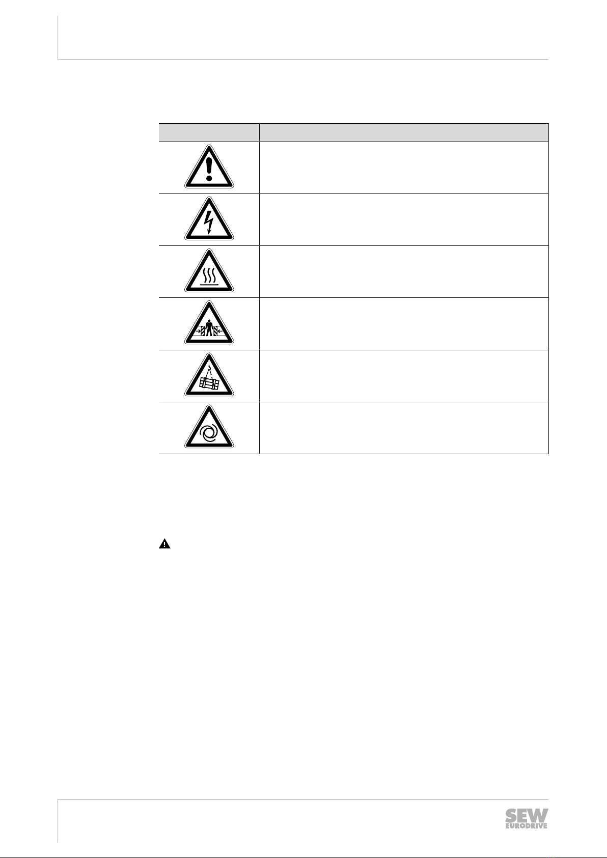
1.3 Structure of the safety notes ...........................................................................................5
1.4 Rights to claim under limited warranty ............................................................................6
1.5 Product names and trademarks......................................................................................6
1.6 Copyright notice ..............................................................................................................7
2 Safety notes .............................................................................................................................. 8
2.1 Preliminary information ...................................................................................................8
2.2 Duties of the user............................................................................................................8
2.3 Target group ...................................................................................................................8
2.4 Designated use ...............................................................................................................9
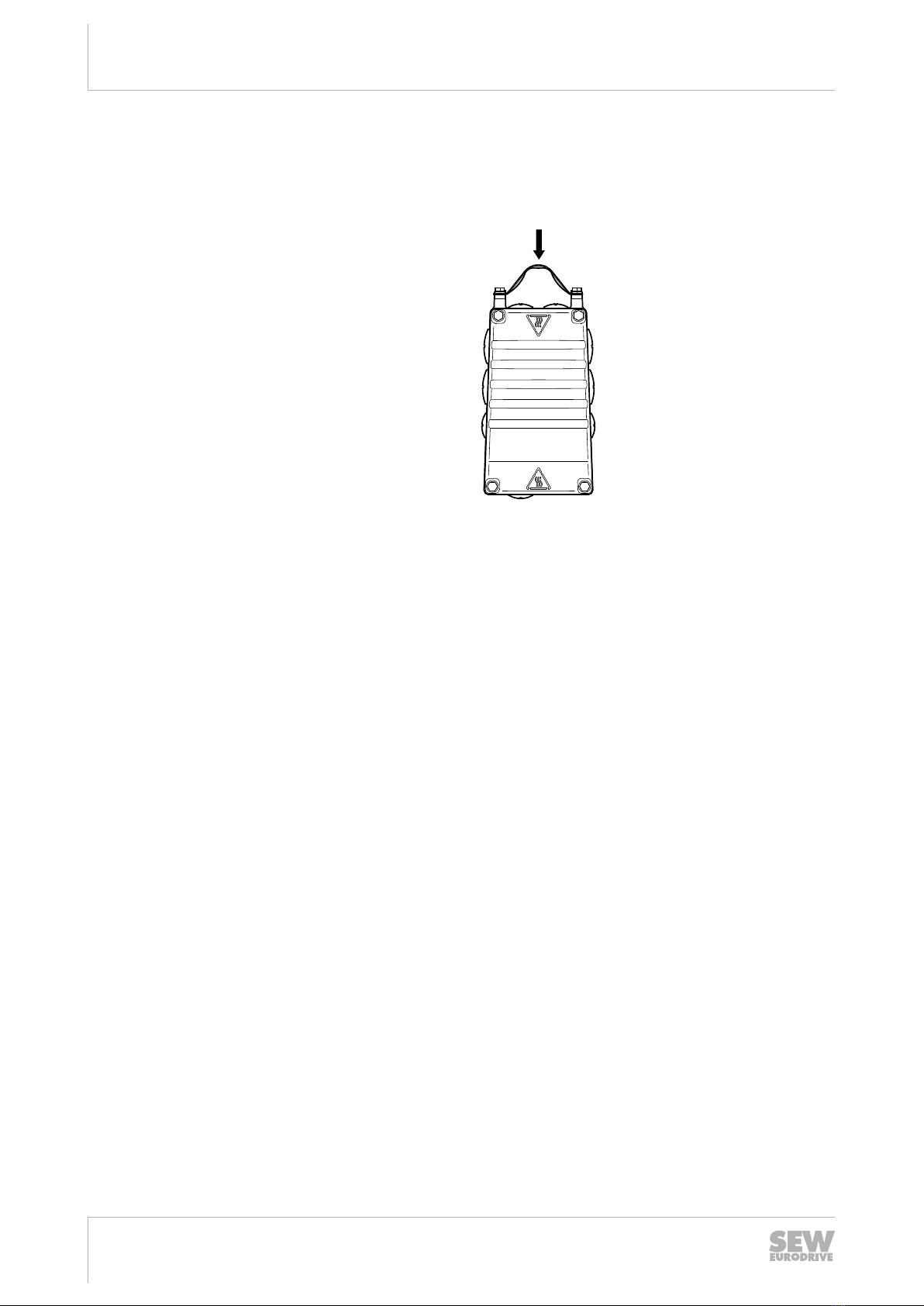
2.5 Transportation.................................................................................................................9
2.6 Installation/assembly.....................................................................................................10
2.7 Electrical connection .....................................................................................................11
2.8 Protective separation ....................................................................................................11
2.9 Startup/operation ..........................................................................................................12
2.10 Magnetic fields..............................................................................................................12
3 Unit structure .......................................................................................................................... 13
3.1 MOVIGEAR® classic drive unit.....................................................................................13
3.2 Shaft types ....................................................................................................................14
3.3 Housing mounting .........................................................................................................15
3.4 Threads for protective cover .........................................................................................16
3.5 Cable entry position ......................................................................................................16
3.6 Nameplate position .......................................................................................................17
3.7 Example nameplate and type designation of drive unit ................................................18
3.8 Cover and connection box ............................................................................................19
4 Mechanical installation .......................................................................................................... 20
4.1 Installation notes ...........................................................................................................20
4.2 Required tools and resources .......................................................................................21
4.3 Installation requirements...............................................................................................21
4.4 Setting up the drive unit ................................................................................................22
4.5 Shaft-mounted gear unit with keyway ...........................................................................27
4.6 Shaft-mounted gear unit with TorqLOC® (customer shaft without contact shoulder) .32
4.7 Shaft-mounted gear unit with TorqLOC® (customer shaft with contact shoulder) .......39
4.8 Shaft-mounted gear unit with TorqLOC® – disassembly, cleaning, lubrication ............44
4.9 Installing the protective cover .......................................................................................46
4.10 Torque arm ...................................................................................................................48
4.11 Tightening torques ........................................................................................................49
5 Electrical installation.............................................................................................................. 52
5.1 Equipotential bonding ...................................................................................................52
5.2 Equipotential bonding at the connection box ................................................................53
5.3 Installation instructions..................................................................................................54
25805134/EN – 07/2018

Table of contents
Operating Instructions – MOVIGEAR® classic
4
5.4 Installation topologies ...................................................................................................58
5.5 Terminal assignment.....................................................................................................60
5.6 Thermal motor protection..............................................................................................61
6 Startup ..................................................................................................................................... 63
6.1 Startup notes.................................................................................................................63
6.2 Prerequisites for startup................................................................................................63
7 Service..................................................................................................................................... 64
7.1 Malfunctions of the mechanical drive............................................................................64
7.2 SEW‑EURODRIVE Service ..........................................................................................66
7.3 Extended storage..........................................................................................................66
7.4 Waste disposal..............................................................................................................68
8 Inspection and maintenance ................................................................................................. 69
8.1 Inspection and maintenance intervals...........................................................................69
8.2 Lubricant change intervals ............................................................................................71
8.3 Inspection and maintenance work ................................................................................72
8.4 Changing the oil ............................................................................................................73
8.5 Replacing the output oil seal.........................................................................................75
8.6 Painting the drive unit ...................................................................................................75
8.7 Cleaning the drive unit ..................................................................................................76
8.8 Connection cables ........................................................................................................76
8.9 Replacing the gasket between connection box and cover............................................77
9 Technical data and dimension sheets.................................................................................. 81
9.1 Conformity.....................................................................................................................81
9.2 General technical data ..................................................................................................82
9.3 Current carrying capacity of terminals ..........................................................................82
9.4 Derating for increased ambient temperature ................................................................83
9.5 Motor data for MOVIGEAR® classic ............................................................................84
9.6 Technical data for the PK (PT1000) temperature sensor .............................................85
9.7 Permitted currents, speeds and torques .......................................................................86
9.8 Surface protection.........................................................................................................88
9.9 Screw fittings.................................................................................................................90
9.10 Mounting positions........................................................................................................91
9.11 Lubricants .....................................................................................................................93
9.12 Design notes for gear units with hollow shaft and key................................................100
9.13 Dimension drawings....................................................................................................104
10 Address list ........................................................................................................................... 109
Index ...................................................................................................................................... 120
25805134/EN – 07/2018

1
General information
About this documentation
Operating Instructions – MOVIGEAR® classic 5
1 General information
1.1 About this documentation
The current version of the documentation is the original.
This documentation is an integral part of the product. The documentation is written for
all employees who assemble, install, start up, and service this product.
Make sure this documentation is accessible and legible. Ensure that persons respons-
ible for the machinery and its operation as well as persons who work on the product
independently have read through the documentation carefully and understood it. If you
are unclear about any of the information in this documentation or require further in-
formation, contact SEW‑EURODRIVE.
1.2 Other applicable documentation
Observe the corresponding documentation for all further components.
1.3 Structure of the safety notes
1.3.1 Meaning of signal words
The following table shows the grading and meaning of the signal words for safety
notes.
Signal word Meaning Consequences if disregarded
DANGER Imminent hazard Severe or fatal injuries
WARNING Possible dangerous situation Severe or fatal injuries
CAUTION Possible dangerous situation Minor injuries
NOTICE Possible damage to property Damage to the product or its envir-
onment
INFORMATION Useful information or tip: Simplifies
handling of the product.
1.3.2 Structure of section-related safety notes
Section-related safety notes do not apply to a specific action but to several actions
pertaining to one subject. The hazard symbols used either indicate a general hazard
or a specific hazard.
This is the formal structure of a safety note for a specific section:
SIGNAL WORD
Type and source of hazard.
Possible consequence(s) if disregarded.
• Measure(s) to prevent the hazard.
25805134/EN – 07/2018

1General information
Rights to claim under limited warranty
Operating Instructions – MOVIGEAR® classic
6
Meaning of the hazard symbols
The hazard symbols in the safety notes have the following meaning:
Hazard symbol Meaning
General hazard
Warning of dangerous electrical voltage
Warning of hot surfaces
Warning of risk of crushing
Warning of suspended load
Warning of automatic restart
1.3.3 Structure of embedded safety notes
Embedded safety notes are directly integrated into the instructions just before the de-
scription of the dangerous action.
This is the formal structure of an embedded safety note:
SIGNAL WORD Type and source of hazard. Possible consequence(s) if disreg-
arded. Measure(s) to prevent the hazard.
1.4 Rights to claim under limited warranty
Read the information in this documentation. This is essential for fault-free operation
and fulfillment of any rights to claim under limited warranty. Read the documentation
before you start working with the product.
1.5 Product names and trademarks
The brands and product names in this documentation are trademarks or registered
trademarks of their respective titleholders.
25805134/EN – 07/2018

1
General information
Copyright notice
Operating Instructions – MOVIGEAR® classic 7
1.6 Copyright notice
©2018SEW‑EURODRIVE. All rights reserved. Unauthorized reproduction, modifica-
tion, distribution or any other use of the whole or any part of this documentation is
strictly prohibited.
25805134/EN – 07/2018

2Safety notes
Preliminary information
Operating Instructions – MOVIGEAR® classic
8
2 Safety notes
2.1 Preliminary information
The following general safety notes have the purpose to avoid injury and damage to
property. They primarily apply to the use of products described in this documentation.
If you use additional components also observe the relevant warning and safety notes.
2.2 Duties of the user
As the user, you must ensure that the basic safety notes are observed and complied
with. Make sure that persons responsible for the machinery and its operation as well
as persons who work on the device independently have read through the documenta-
tion carefully and understood it.
As the user, you must ensure that all of the work listed in the following is carried out
only by qualified specialists:
• Setup and installation
• Installation and connection
• Startup
• Maintenance and repairs
• Shutdown
• Disassembly
Ensure that the persons who work on the product pay attention to the following regula-
tions, conditions, documentation, and information:
• National and regional safety and accident prevention regulations
• Warning and safety signs on the product
• All other relevant project planning documents, installation and startup instructions,
and wiring diagrams
• Do not assemble, install or operate damaged products
• All system-specific specifications and conditions
Ensure that systems in which the product is installed are equipped with additional
monitoring and protection devices. Observe the applicable safety regulations and le-
gislation governing technical work equipment and accident prevention regulations.
2.3 Target group
Specialist for
mechanical work
Any mechanical work may only be performed by adequately qualified specialists. Spe-
cialists in the context of this documentation are persons familiar with the design,
mechanical installation, troubleshooting, and maintenance of the product who possess
the following qualifications:
• Qualification in the mechanical area in accordance with the national regulations
• Familiarity with this documentation
25805134/EN – 07/2018

2
Safety notes
Designated use
Operating Instructions – MOVIGEAR® classic 9
Specialist for elec-
trotechnical work
Any electrotechnical work may only be performed by electrically skilled persons with a
suitable education. Electrically skilled persons in the context of this documentation are
persons familiar with electrical installation, startup, troubleshooting, and maintenance
of the product who possess the following qualifications:
• Qualification in the electrotechnical area in accordance with the national regula-
tions
• Familiarity with this documentation
Additional qualifi-
cation
In addition to that, these persons must be familiar with the valid safety regulations and
laws, as well as with the requirements of the standards, directives, and laws specified
in this documentation. The persons must have the express authorization of the com-
pany to operate, program, parameterize, label, and ground units, systems, and circuits
in accordance with the standards of safety technology.
Instructed persons All work in the areas of transportation, storage, operation and waste disposal must be
carried out by persons who are trained appropriately. The purpose of the instruction is
that the persons are capable of performing the required tasks and work steps in a safe
and correct manner.
2.4 Designated use
The product is intended for installation in electrical plants or machines.
In case of installation in electrical systems or machines, startup of the product is pro-
hibited until it is determined that the machine meets the requirements stipulated in the
local laws and directives. For Europe, Machinery Directive 2006/42/EC as well as the
EMC Directive 2014/30/EU apply. Observe EN60204-1 (Safety of machinery - elec-
trical equipment of machines). The product meets the requirements stipulated in the
Low Voltage Directive 2014/35/EU.
The standards given in the declaration of conformity apply to the product.
Technical data and information on the connection conditions are provided on the
nameplate and in chapter "Technical data" in the documentation. Always comply with
the data and conditions.
Unintended or improper use of the product may result in severe injury to persons and
damage to property.
Do not use the product as a climbing aid.
2.4.1 Lifting applications
The product may not be used for lifting applications or on slopes.
2.5 Transportation
Inspect the shipment for damage as soon as you receive the delivery. Inform the ship-
ping company immediately about any damage. If the product is damaged, it must not
be assembled, installed or started up.
Observe the following notes when transporting the device:
• Ensure that the product is not subject to mechanical impact.
• Do not attach any additional loads.
25805134/EN – 07/2018

2Safety notes
Installation/assembly
Operating Instructions – MOVIGEAR® classic
10
If necessary, use suitable, sufficiently dimensioned handling equipment.
Observe the information on climatic conditions in chapter "Technical data" of the docu-
mentation.
The following figure shows the position of the lifting eye.
PE W V U
X4
X2
+ -
KTY
28228871
21488241163
2.6 Installation/assembly
Ensure that the product is installed and cooled according to the regulations in the doc-
umentation.
Protect the product from excessive mechanical strain. The product and its mounted
components must not protrude into the path of persons or vehicles. Ensure that com-
ponents are not deformed and that insulation spaces are maintained, particularly dur-
ing transportation. Electric components must not be mechanically damaged or des-
troyed.
Observe the notes in the chapter "Mechanical installation" of the documentation.
25805134/EN – 07/2018

2
Safety notes
Electrical connection
Operating Instructions – MOVIGEAR® classic 11
2.6.1 Restrictions of use
The following applications are prohibited unless explicitly permitted:
• Use in potentially explosive areas
• Use in areas exposed to harmful oils, acids, gases, vapors, dust, and radiation
• Operation in applications with impermissibly high mechanical vibration and shock
loads in excess of the regulations stipulated in EN61800-5-1
• Operation at installation altitudes above 4000 m above sea level
2.7 Electrical connection
Make yourself familiar with the applicable national accident prevention guidelines be-
fore you work on the product.
Perform electrical installation according to the pertinent regulations (e.g. cable cross
sections, fusing, protective conductor connection). The documentation at hand con-
tains additional information.
Make sure that all required covers are installed correctly after electrical installation.
Make sure that preventive measures and protection devices comply with the applic-
able regulations (e.g. EN60204-1 or EN61800-5-1).
2.7.1 Stationary application
Necessary preventive measure for the product is:
Type of energy transfer Preventive measure
Direct power supply • Ground connection
2.7.2 Regenerative operation
The drive is operated as a generator due to the kinetic energy of the system/machine.
Before opening the connection box, secure the output shaft against rotation.
2.8 Protective separation
The product meets all requirements for protective separation of power and electronics
connections in accordance with EN 61800-5-1. To ensure protective separation, all
connected circuits must also meet the requirements for protective separation.
25805134/EN – 07/2018

2Safety notes
Startup/operation
Operating Instructions – MOVIGEAR® classic
12
2.9 Startup/operation
Observe the safety notes in the chapters "Startup" and "Operation" in the documenta-
tion.
Make sure that the present transport protection is removed.
Do not deactivate monitoring and protection devices of the machine or system even
for a test run.
Make sure the connection boxes are closed and screwed before connecting the sup-
ply voltage.
Depending on the degree of protection, products may have live, uninsulated, and
sometimes moving or rotating parts, as well as hot surfaces during operation.
Additional preventive measures may be required for applications with increased haz-
ard potential. You have to check the protection devices after each modification.
When in doubt, switch off the product whenever changes occur in relation to normal
operation. Possible changes are e.g. increased temperatures, noise, or oscillation. De-
termine the cause. Contact SEW‑EURODRIVE if necessary.
When the device is switched on, dangerous voltages are present at all power connec-
tions as well as at any connected cables and terminals. This also applies even when
the product is inhibited and the motor is at standstill.
Mechanical blocking or internal safety functions of the product can cause a motor
standstill. Eliminating the cause of the problem or performing a reset may result in the
drive re-starting automatically. If, for safety reasons, this is not permitted for the drive-
controlled machine, first disconnect the product from the supply system and then start
troubleshooting.
Risk of burns: The surface temperature of the product can exceed 60°C during opera-
tion.
Do not touch the product during operation.
Let the product cool down before touching it.
2.10 Magnetic fields
The device contains permanent magnets that create strong magnetic fields even when
de-energized. Magnetic fields may pose a health risk. This especially applies to per-
sons with active medical implants. During operation, additional electromagnetic fields
are generated.
Observe DGUV (German Social Accident Insurance) regulation15–"Electromagnetic
fields" for use in industrial workplaces. In other countries, the corresponding national
and local regulations and provisions must be complied with.
25805134/EN – 07/2018

3
Unit structure
MOVIGEAR® classic drive unit
Operating Instructions – MOVIGEAR® classic 13
3 Unit structure
3.1 MOVIGEAR® classic drive unit
MOVIGEAR
® classic
drive unit
MOVIGEAR® classic is a unit consisting of a gear unit and a synchronous motor in a
compact aluminum die-cast housing (see following figure).
[5]
[3]
[4]
[1]
[6]
[2]
MGF..1-DSM-C
21491248523
[1] Cover
[2] Option /PE (pressure compensation fitting electronics)
[3] Gear unit cover
[4] Output shaft variant (pictured here: hollow shaft with keyway)
[5] Optional safety cover
[6] Connection box for cable glands
25805134/EN – 07/2018

3Unit structure
Shaft types
Operating Instructions – MOVIGEAR® classic
14
3.2 Shaft types
MOVIGEAR® classic is available with the following shaft variants:
3.2.1 MOVIGEAR® classic with hollow shaft and keyway (MGFA.)
The following figure shows a MOVIGEAR® classic unit with hollow shaft and keyway:
21491880203
3.2.2 MOVIGEAR® classic with TorqLOC® hollow shaft mounting system (MGFT.)
The following figure shows a MOVIGEAR® classic unit with TorqLOC® hollow shaft
mounting system:
21491883147
25805134/EN – 07/2018

3
Unit structure
Housing mounting
Operating Instructions – MOVIGEAR® classic 15
3.3 Housing mounting
3.3.1 Torque arm (MGF.T)
The following figure shows the torque arm for MOVIGEAR® classic:
21491911691
3.3.2 Housing with threads (MGF.S)
WARNING
Improper installation of the drive unit without torque arm.
Severe or fatal injuries.
• Only mount the drive units to the plant structure together with a torque arm. In-
stallation without a torque arm is not permitted.
The following figure shows the housing type with threads for mounting a torque arm.
This type does not include a centering shoulder, which means it is not suitable for dir-
ect installation to the plant structure:
21491914635
25805134/EN – 07/2018

3Unit structure
Threads for protective cover
Operating Instructions – MOVIGEAR® classic
16
3.4 Threads for protective cover
NOTICE
Impermissible use of the threads.
Damage to the drive unit.
• The threads may only be used for other applications after consultation with
SEW‑EURODRIVE.
• SEW‑EURODRIVE assumes no guarantee or liability for resulting product dam-
ages.
The following figure shows the threads used for fastening the protective cover:
[1]
21532510603
[1] Threads for protective cover (4×)
3.5 Cable entry position
The following cable entries are possible for MOVIGEAR® classic MGF..1-DSM-C:
• Position X+1+2+3
– X: 2×M25×1.5+1×M16×1.5
– 1: 1×M16×1.5
– 2: 2×M25×1.5+1×M16×1.5
– 3: 2×M16×1.5
25805134/EN – 07/2018

3
Unit structure
Nameplate position
Operating Instructions – MOVIGEAR® classic 17
3.5.1 Overview
The following figure shows the possible cable entries:
3
12
X
3
1
X
2
21491919115
3.6 Nameplate position
The following nameplate positions are possible for MOVIGEAR® classic:
• X
• 2
• 3 (standard position)
3.6.1 Overview
The following figure shows the possible positions:
76646Bruchsal/Germany
MGFAT1-DSM-C/PE
01.7244152929.0001.18
IMM1, M2, M4, M5, M6
Ta-20...+40°C
Th.Kl.155(F)
CLPHC 220 Synth. Öl/PSS/0.36l
i29.32
TENV 3~ IEC60034 Inverter duty VPWM ML13
nA 68.2 r/min
IO 1.11A
ID 1.11A
Imax 1.95A
IP65 7.6 Kg nmax 2000 r/min
UN400V
MA 62 Nm
Mapk108 Nm
Up282V
Madein Germany
2810635 0.10
IE5
eff%81.2
76646Bruchsal/Germany
MGFAT1-DSM-C/PE
01.7244152929.0001.18
IMM1, M2, M4, M5, M6
Ta-20...+40°C
Th.Kl.155(F)
CLPHC 220 Synth. Öl/PSS/0.36l
i29.32
TENV 3~ IEC60034 Inverter duty VPWM ML13
nA 68.2r/min
IO 1.11A
ID 1.11A
Imax 1.95A
IP65 7.6 Kg nmax 2000 r/min
UN400 V
MA 62 Nm
Mapk 108Nm
Up282 V
MadeinGermany
2810635 0.10
IE5
eff%81.2
2
X3
76646 Bruchsal/Germany
MGFAT1-DSM-C/PE
01.7244152929.0001.18
IM M1, M2, M4, M5, M6
Ta -20...+40°C
Th.Kl.155(F)
CLP HC 220 Synth. Öl/PSS/0.36l
i 29.32
TENV 3~ IEC60034 Inverter duty VPWM ML13
nA 68.2 r/min
IO 1.11 A
ID 1.11 A
Imax 1.95 A
IP 65 7.6 Kg nmax 2000 r/min
UN 400 V
MA 62 Nm
Ma pk 108 Nm
Up 282 V
Made in Germany
2810 635 0.10
IE5
eff% 81.2
27021620111034123
25805134/EN – 07/2018

3Unit structure
Example nameplate and type designation of drive unit
Operating Instructions – MOVIGEAR® classic
18
3.7 Example nameplate and type designation of drive unit
3.7.1 Nameplate
The following figure gives an example of a MOVIGEAR® classic nameplate. For the
structure of the type designation, refer to chapter "Type designation".
>@76646 Bruchsal/Germany
MGFAT1-DSM-C/PE
01.7244152929.0001.18
IM M1, M2, M4, M5, M6
Ta -20...+40°C
Th.Kl.155(F)
CLP HC 220 Synth. Öl/PSS/0.36l
i 29.32
TENV 3~ IEC60034 Inverter duty VPWM ML13
nA 68.2 r/min
IO 1.11 A
ID 1.11 A
Imax 1.95 A
IP 65 7.6 Kg nmax 2000 r/min
UN 400 V
MA 62 Nm
Ma pk 108 Nm
Up 282 V
Made in Germany
2810 635 0.10
IE5
eff% 81.2
>@
27021619256096907
[1] The QR code on the nameplate represents the unique serial number (with
period as separator).
[2] Unique serial number
3.7.2 Type designation
The following table shows the MOVIGEAR® classic type designation:
MG Product family
MG = MOVIGEAR®
F Gear unit type
F = Parallel-shaft helical gear unit
A Shaft design
A = Shaft-mounted gear unit (hollow shaft with key)
T = TorqLOC® hollow shaft mounting system
T Housing mounting
T = Drive with torque arm
S = Housing with threads for mounting a torque arm
1 Size
1 = Torque class 100Nm
–
DSM Design
DSM = classic (without electronics)
–
C Generation
/
PE Option
PE = Pressure compensation fitting electronics
25805134/EN – 07/2018

3
Unit structure
Cover and connection box
Operating Instructions – MOVIGEAR® classic 19
3.8 Cover and connection box
The following figure shows the connection box and cover on the MOVIGEAR® classic
MGF..1-DSM-C:
PE W V U
X2
28228871
[2] [3] [4] [5] [3] [1][1] [1] [6]
[7] [7][1][1] [7][7]
X4
+-
KTY
PK
[8]
21491922059
[1] Cable glands
[2] Connection box
[3] Terminals for internal wiring
[4] Part number of the connection board
[5] Terminals X2 for motor connection PE, W, V, U
[6] Cover
[7] Screws for PE connection
[8] Terminals X4 for PK (PT1000) temperature sensor
25805134/EN – 07/2018

4Mechanical installation
Installation notes
Operating Instructions – MOVIGEAR® classic
20
4 Mechanical installation
4.1 Installation notes
INFORMATION
Adhere to the safety notes during installation.
WARNING
Improper installation/disassembly of drive unit and mount-on components.
Serious injuries.
• Adhere to the notes about installation and disassembly.
• Before releasing shaft connections, make sure that there are no active torsional
moments present (tensions within the system).
WARNING
Improper installation of the drive unit without torque arm.
Severe or fatal injuries.
• Only mount the drive units to the plant structure together with a torque arm. In-
stallation without a torque arm is not permitted.
WARNING
Risk of injury if the drive unit starts up unintentionally and danger of electrical
voltage.
Severe or fatal injuries.
• Disconnect the drive unit from the power supply with suitable external measures
before you start working on the unit and secure it against unintentional reconnec-
tion to the voltage supply.
• Secure the output shaft against rotation.
WARNING
Risk of injury caused by rapidly moving output elements.
Serious injuries.
• Disconnect the drive unit from the power supply and safeguard it against uninten-
tional power up before you start working on it.
• Equip the input and output elements (e.g. customer shaft with contact shoulder or
clamping ring, shrink disk) with a touch guard.
25805134/EN – 07/2018
This manual suits for next models
3
Table of contents
Other SEW-Eurodrive Industrial Electrical manuals
Popular Industrial Electrical manuals by other brands

Daikin
Daikin TYPE4 Checker instruction manual

hager
hager univers N UK31LH1FM Mounting instructions

Bofa
Bofa V600 user manual

Murata
Murata GJM0335C1E330GB01 Series Reference sheet

Comar Condensatori
Comar Condensatori BMR Series Installation and operating instructions

Murata
Murata GRM0335C2A7R9DA01 Series Reference sheet

Murata
Murata GRJ21BR71H105KE01 Series Reference sheet

Murata
Murata GRM033R60J225ME47 Series Reference sheet

Murata
Murata GRM32ER61A226KE20 Series Reference sheet

Murata
Murata GRM0225C1E120GA03 Series Reference sheet

Murata
Murata GRM0335C1E6R2DA01 Series Reference sheet

Murata
Murata GRM0335C1E910JA01 Series Reference sheet