Elura AMP 150/2 User manual
model # AMP 150/2
high performance amplifier
S/N:
4/8Ω
NORMAL
BRIDGED
FR LP
R+
R-
L-
L+
8ΩONLY
-
+
ON
AUTO
POWER
MODE
IN OUT
TRIGGER DC 12V
HP
BRIDGED
8ΩONLY
SPEAKER OUTPUT
OUT IN
L
BRIDGED
R
1 2
POWER
Overview.
Thank you for purchasing Elura
Amplifier products. Elura is a high
performance custom installed
product engineered for movie and
music enthusiasts. Each Elura
product is manufactured to the
highest quality standard using state
of the art components and built for
years of enjoyment.
Features.
• Digital high power amplification
• Low impedance
• Bridgeable
• Low Noise
• Small chassis
• Less Heat
• Efficient design
• Rack mountable
• Automation circuit
Contents.
• Amplifier
• Rack Mounting Hardware
• Power cord
• Manual
Warning.
To reduce the risk of electric shock,
do not expose this product to rain or
moisture. This product should not
be exposed to dripping or splashing
and avoid placing near any object
filled with water, such as a vase or
an aquarium.
Important Symbols.
The lighting flash arrowhead
triangular symbol is to alert the user
to the presence of uninsulated
‘dangerousvoltage’ within the
product sufficient enough to
constitute a risk of electric shock.
The arrowhead symbol with an
exclamation point is to alert the user
to the presence of an important
operational or maintenance
instruction.
Safety Instructions.
1. Read the instructions.
2. Keep the instructions.
3. Heed all warnings.
4. Follow the instructions.
5. Do not use near water.
6. Clean with a dry cloth.
7. Do not block ventilation slots.
8. Install in accordance to the
instructions.
9. Do not install near a heat source
or combustible source.
10. Do not defeat the polarized or
grounding plug.
11. Protect the power cord from
being crimped, cut or pinched.
12. Only attached accessories
specified within the instructions.
13. Use only on lower shelves with
a stand, cart or rack product
capable of holding the weight to
avoid injury from furniture tipping
over.
model # AMP 150/2
high performance amplifier
The M-AMP 150/2 has three power
modes, ON / AUTO / TRIGGERED.
ON = Always ON
AUTO = Signal sensing via audio
TRIGGERED = 12VDC tip positive
Amplifiers produce light noise when
left on. The noise is a light hiss and
is heard when music isn’t playing in
a very quiet room. If you are using
a master switch to turn off power
to your audio equipment, always
on is acceptable. In a louder or light
commercial environment, always ON
may be acceptable. In quiet rooms,
it is suggested to use AUTO or
TRIGGERED options.
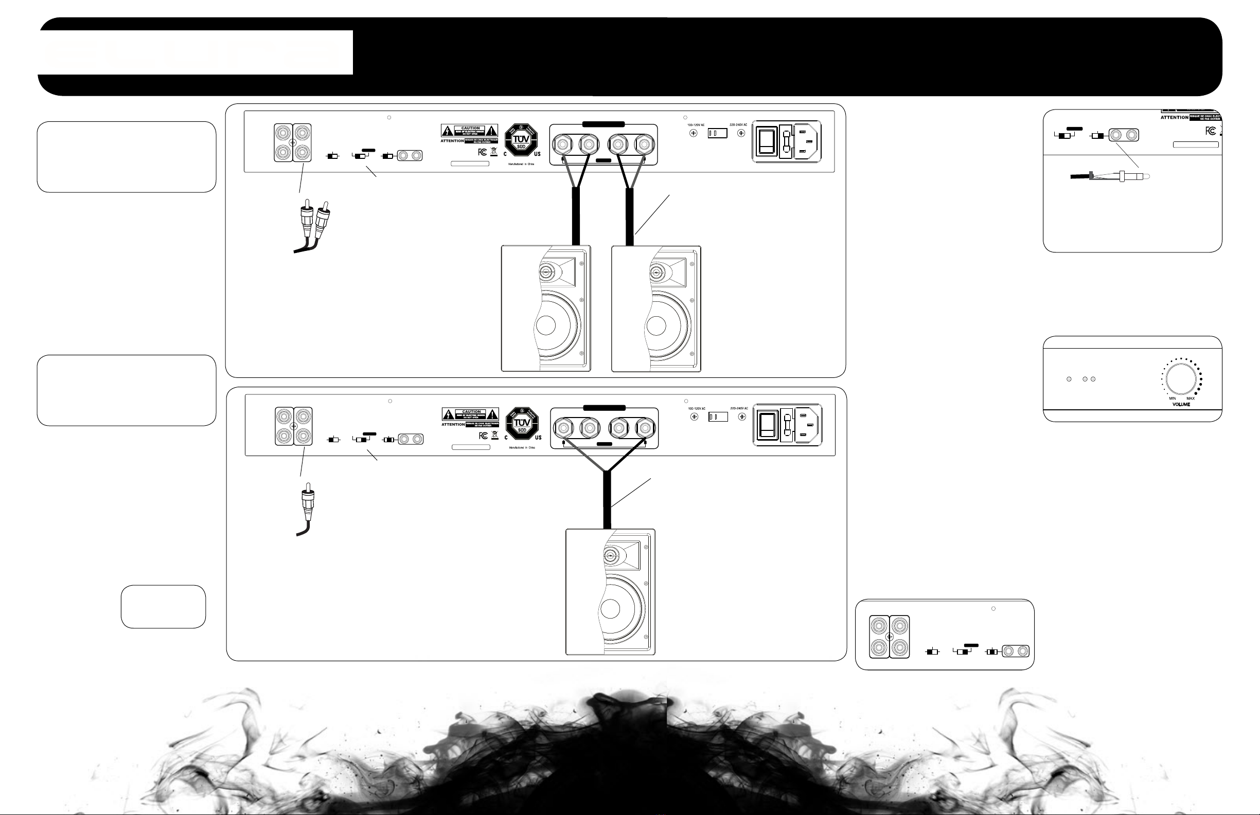
Bridging.
Bridging offers the user more power
to the speaker. The comprimise is
that you lose a channel of the am-
plifier and the lowest impedance in
bridge mode is 8 Ω. Bridging is an
excellent way to increase the power
to a pair of larger speaker. The dia-
gram to the left shows an amplifier
connected to a single speaker. For
a pair, you would need two amplifi-
ers and repeat the conenctions for
left and right source outputs and
speaker connections. See the image
to the left for more details.
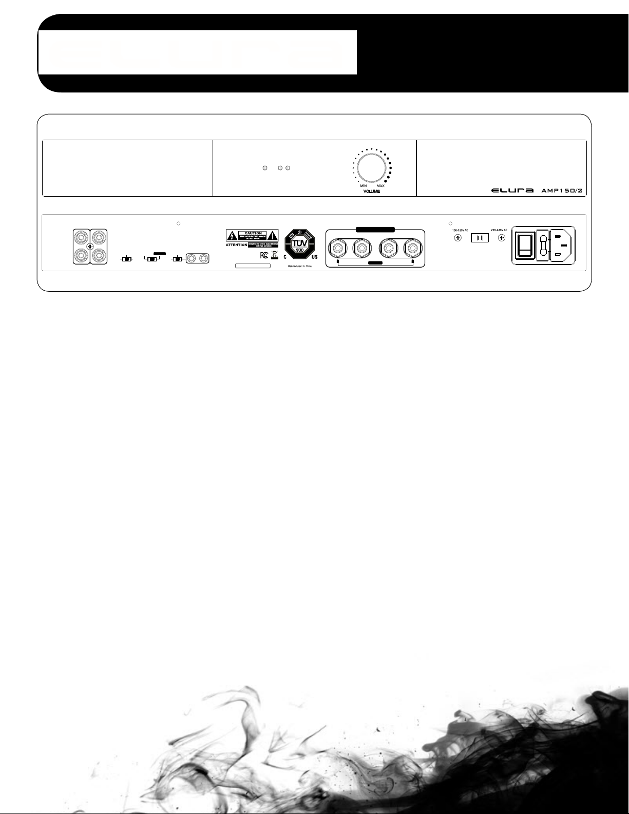
Amp Volume Settings.
The volume for the amplifier is on the
front panel offer integrated control of
the speaker output for Left / Right.
Auto Power Modes.
Speaker Connections.
The AMP 150/2 has 5-way binding
posts to makeconnecting your
speaker wire easy and secure. The
connector can be used to screw
down onto bare wire, or banana
jacks,spade connectors or pins.
Position and polarity are color
coded and marked to avoid phase
issues. Be sure to follow and main-
tain proper polarity and position.
Preamp Connections.
Preamplified connections are made
using Stereo RCA patch cables.
The AMP 150/2 provides a con-
venient IN and OUT loop. Use the
output to connect to another amp
or other device sharing the pre-
amp source signal. Other high-end
options include using the amplifier’s
built in EQ filters to amplify just the
low frequencies or the high frequen-
cies using the FR/HP/LP switch.
FR= Full Range
HP= High Pass
LP= Low Pass
S/N:
4/8Ω
NORMAL
BRIDGED
FR LP
R+
R-
L-
L+
8ΩONLY
-
+
ON
AUTO
POWER
MODE
IN OUT
TRIGGER DC 12V
HP
BRIDGED
8ΩONLY
SPEAKER OUTPUT
OUT IN
L
BRIDGED
R
CL2, 2 conductor,
16 AWG speaker wire
FR = Full Range
4/8 Ω Normal
Power Mode ON
To amplier IN
From
preamplied
source
Stereo 2-Channel
S/N:
4/8Ω
NORMAL
BRIDGED
FR LP
R+
R-
L-
L+
8ΩONLY
-
+
ON
AUTO
POWER
MODE
IN OUT
TRIGGER DC 12V
HP
BRIDGED
8ΩONLY
SPEAKER OUTPUT
OUT IN
L
BRIDGED
R
CL2, 2 conductor,
16 AWG speaker wire
FR = Full Range
BRIDGED 8 Ω ONLY
Power Mode AUTO
To amplier IN,
Left Input
Bridged
From
preamplied
source
Bridged Single Channel,
load can not be lower
than 8 Ω
Repeat for Left and
Right connections
for high powered
Stereo Pair
S/N:
4/8Ω
NORMAL
BRIDGED
FR LP
R+
R-
L-
L+
8ΩONLY
-
+
ON
AUTO
POWER
MODE
IN OUT
TRIGGER DC 12V
HP
BRIDGED
8ΩONLY
SPEAKER OUTPUT
OUT IN
L
BRIDGED
R
S/N:
4/8Ω
NORMAL
BRIDGED
FR LP
R+
R-
L-
L+
8ΩONLY
-
+
ON
AUTO
POWER
MODE
IN OUT
TRIGGER DC 12V
HP
BRIDGED
8ΩONLY
SPEAKER OUTPUT
OUT IN
L
BRIDGED
R
+
-
Use a mono 1/8” jack to connect to a
12VDC output from another source,
relay, or power supply.
( 9 to 12VDC, 100 mA minimum )
Tip Positive
Ground Sleeve
1 2
POWER
Front Panel LEDs.
The Elura amplifiers have LEDs on
the front panel to indicate the ampli-
fier’s power state and channel
status. The Power LED indicates
the amplifier is ON. There is a LED
indicating the channel state. The
LEDs can be used to identify and
trouble shoot channels that are
not working. If a channel is in fault
mode, power down the amp, identi-
fy and fix the issue. When complete
power up the amp to recheck it has
been resolved.
Power ON = Blue
Power OFF = Red
Channel Normal = Blue
Channel Fault = Red
Channel fault conditions are
shortcircuit, thermal, or overload
failures.
model AMP 150/2
high performance amplifier
Warranty.
All Elura products come with a 2
year limited liability warranty. This
warranty includes parts and labor re-
pairs on all components found to be
defective in material or workmanship
under normal conditions of use. This
warranty shall not apply to products
which have been abused, modified
or disassembled. Warranty items
only by authorized resellers.
Warranty not eligible for products
purchased through non-authorized
online sellers.
A product that fails under condi-
tions other than those covered will
be repaired at the current price of
parts and labor in effect at the time
of repair. Such repairs are warranted
for 90 days from the day of reship-
ment to the BUYER. If the unit is
delivered by mail, customers agree
to insure the unit or assume the risk
of loss or damage in transit. Un-der
no circumstances will a unit be
accepted without a return authoriza-
tion number. The warranty is in lieu
of all other warranties expressed or
implied, including without limitations,
any other implied warranty or fitness
or merchantability for any particular
purpose, all of which are expressly
disclaimed. Proof of sale may be
required in order to claim warranty.
www.elura.audio
S/N:
4/8Ω
NORMAL
BRIDGED
FR LP
R+
R-
L-
L+
8ΩONLY
-
+
ON
AUTO
POWER
MODE
IN OUT
TRIGGER DC 12V
HP
BRIDGED
8ΩONLY
SPEAKER OUTPUT
OUT IN
L
BRIDGED
R
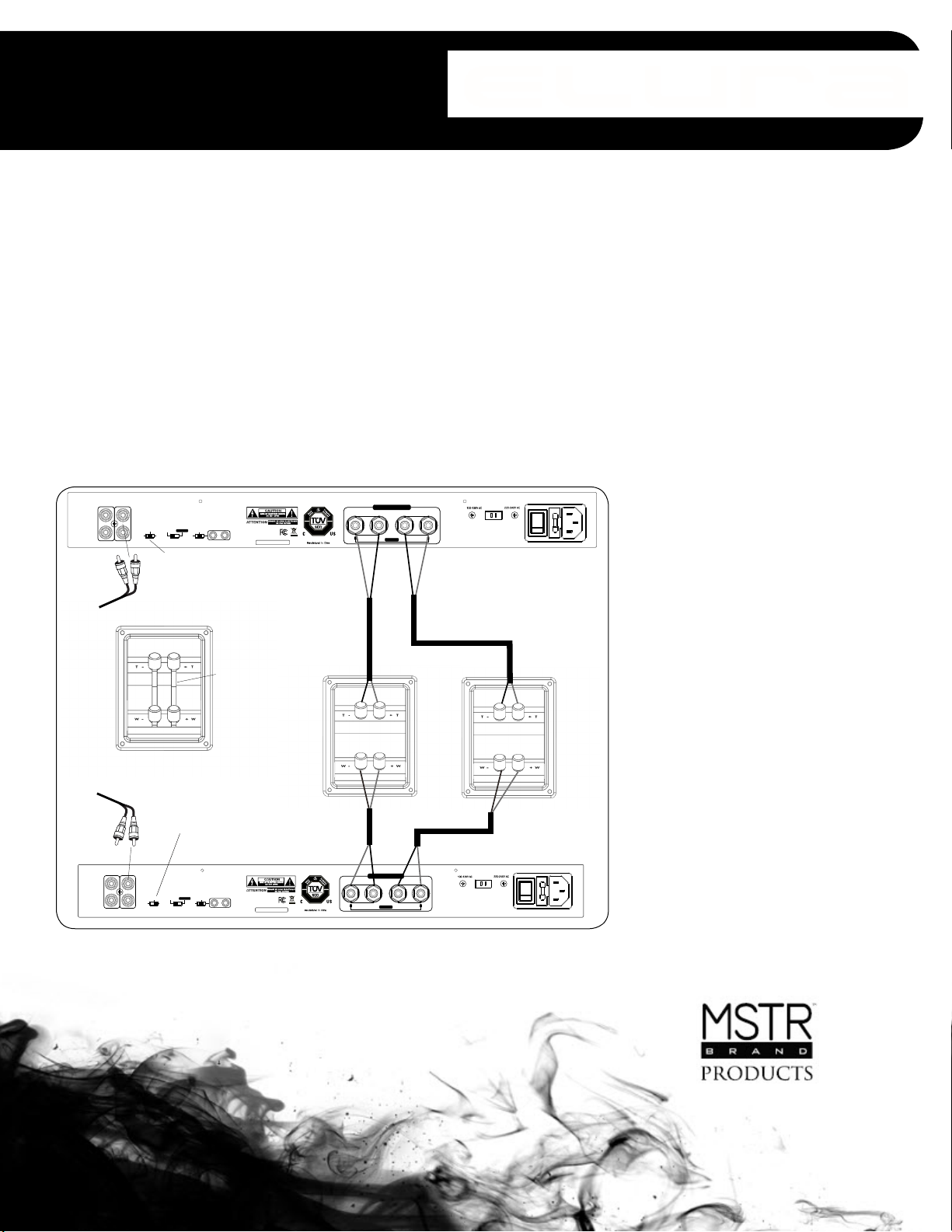
From audio source
to L/R input
High Pass
Position
Unscrew terminals and
remove the bridging clips
on the back of the speaker
Amplier #1 feeds the tweeters
in the speaker system
Amplier #1
Left speaker
terminal cup
Right speaker
terminal cup
S/N:
4/8Ω
NORMAL
BRIDGED
FR LP
R+
R-
L-
L+
8ΩONLY
-
+
ON
AUTO
POWER
MODE
IN OUT
TRIGGER DC 12V
HP
BRIDGED
8ΩONLY
SPEAKER OUTPUT
OUT IN
L
BRIDGED
R
Amplifer #2
Low Pass Position
From audio out of
Amplifer 1
Amplier #2 feeds the woofers
in the speaker system
Bi-amping.
Bi-amping your speakers using two
AMP150/2 amplifiers is an excellent
and efficient way to get the most out
of your speakers. In this case, the
frequencies are crossovered in the
amplifier and the speakers drivers are
fed the most power possible directly
to the tweeters and the drivers. Each
speaker is driven by an amplifier
channel bypassing the crossover
components. While this setup can be
a little more complicated, the
performance is top notch!
Specifications.
Output Power: 150W x 2 @ 4Ω 1kHz
THD+N: @4Ω=0.9%/ @8Ω=1.0%
Input Sensitivity: 600mV
Frequency Response: 10Hz - 20kHz
High Pass Filter: 150Hz - 20kHz /-3dB
Low Pass Filter: 10Hz - 150Hz / -3dB
Signal to Noise Ratio: -75dB
Auto Turn ON: 5mV
Turn OFF Delay: 8min
Supply Voltage: AC230V / 50Hz
AC110V / 60Hz
Other Elura Amplifier manuals


