Elura AMP 500/1 User manual

model AMP 500/1
subwoofer amplifier
POWER
EQ 1 EQ 3
POWER MODE
EQ 2
SPEAKER OUTPUT
LINE IN
L
R
LFE IN
CROSSOVER PHASE
(Sub 1 +Sub 2) m inimu m 4Ω
Total I mpeda nce
SUB 1
+
-
SUB 2
+
-
DC 12V
IN
OUT AUTO
ON
SETTINGS
VOLUME
TRIGGER
50 200 0°180°
S/N:
Overview.
Thank you for purchasing Elura
Amplifier products. Elura is a high
performance custom installed
product engineered for movie and
music enthusiasts. Each Elura
product is manufactured to the
highest quality standard using state
of the art components and built for
years of enjoyment.
Features.
• Digital high power amplification
• 4 Ohm Impedance Capable
• Thermal & Short Circuit
Protection
• Low Noise
• Small chassis
• Less Heat
•Efficient Class D design
• Rack mountable
• Automation circuit
• Detachable Power Cord
Contents.
• Amplifier
• Rack Mounting Hardware
• Power cord
• Manual
Warning.
To reduce the risk of electric shock,
do not expose this product to rain or
moisture. This product should not
be exposed to dripping or splashing
and avoid placing near any object
filled with water, such as a vase or
an aquarium.
Important Symbols.
The lighting flash arrowhead
triangular symbol is to alert the user
to the presence of uninsulated
‘dangerousvoltage’ within the
product sufficient enough to
constitute a risk of electric shock.
The arrowhead symbol with an
exclamation point is to alert the user
to the presence of an important
operational or maintenance
instruction.
Safety Instructions.
1. Read the instructions.
2. Keep the instructions.
3. Heed all warnings.
4. Follow the instructions.
5. Do not use near water.
6. Clean with a dry cloth.
7. Do not block ventilation slots.
8. Install in accordance to the
instructions.
9. Do not install near a heat source
or combustible source.
10. Do not defeat the polarized or
grounding plug.
11. Protect the power cord from
being crimped, cut or pinched.
12. Only attached accessories
specified within the instructions.
13. Use only on lower shelves with
a stand, cart or rack product
capable of holding the weight to
avoid injury from furniture tipping
over.
model AMP 500/1
subwoofer amplifier
www.elura.audio
Specifications.
Output Power: Line & LFE 500W @ 4Ω
Line & LFE 330W @ 6Ω
Line & LFE 250W @ 8Ω
THD+N: Line & LFE @4Ω=0.04%
Input Sensitivity: Line 124mV / LFE 162mV
Frequency Response: Line 15Hz - 260Hz / LFE 15Hz - 550Hz
Low Pass Crossover: 1W/4Ω 90Hz = 0-3dB, 90Hz - 260Hz
Low Pass Filter: 1W/4Ω, 260Hz=0dB, test point @ 525Hz, 13dB/Octave
Signal to Noise Ratio: 500W @4Ω / 90Hz, 90dB, 1W @4Ω / 90Hz, 65dB
Auto Turn Off Time: 16 min
Supply Voltage: AC230V / 50Hz, AC115V / 60Hz
model AMP 500/1
subwoofer amplifier
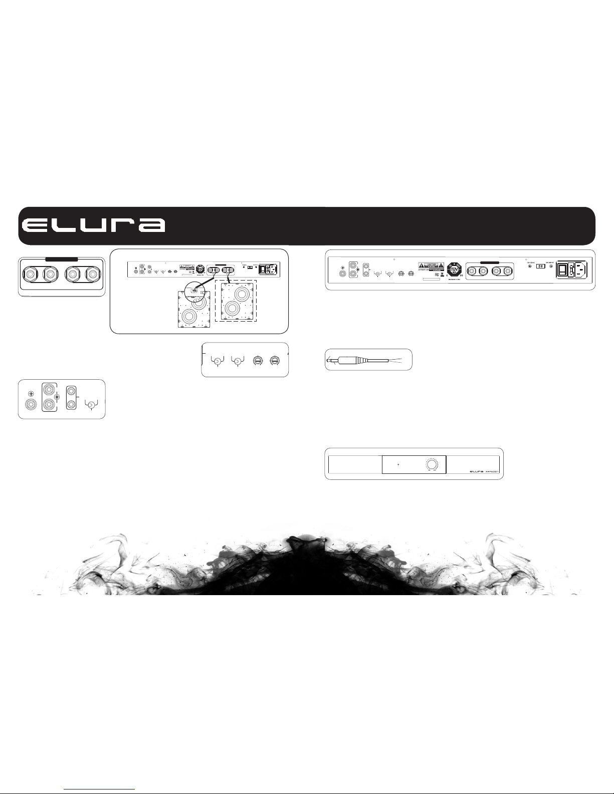
Speaker Connections.
EQ 1 EQ 3
POWER MODE
EQ 2
SPEAKER OUTPUT
LINE IN
L
R
LFE IN
CROSSOVER PHASE
(Sub 1+Sub 2) minimum 4Ω
Tota l Im pe da nc e
SUB 1
+
-
SUB 2
+
-
DC 12V
IN
OUT AUTO
ON
SETTINGS
TRIGGER
50 200 0°180°
S/N:
The AMP500/1 has 5 way binding
post connections for two
subwoofers. The connector can be
used to screw down on bare wire,
banana plugs, spades or pins.
Position and polarity are color
coded and marked to avoid phase
issues. Be sure to follow proper
polarity for each sub and position.
AV Receiver / Preamp
Connections.
Preamplified connections are made
using Stereo RCA patch cables or a
single digital RCA LFE patch cord.
A LFE connection, is a direct path to
the amplifier from the processor or
the AV receiver. The low frequency
effects are crucial for movies.
EQ 1 EQ 3
POWER MODE
EQ 2
SPEAKER OUTPUT
LINE IN
L
R
LFE IN
CROSSOVER PHASE
(Sub 1+Sub 2) minimum 4Ω
Tota l Im pe da nc e
SUB 1
+
-
SUB 2
+
-
DC 12V
IN
OUT AUTO
ON
SETTINGS
TRIGGER
50 200 0°180°
S/N:
EQ Settings.
There are 3 EQ placement settings,
manual crossover frequency, and
phase settings on the rear panel.
The EQ toggle offers three different
curves pending the placement
location and applications. Using the
LFE input bypasses these functions
and uses the cross over settings in
the AV receiver.
EQ 1, toggle left position, is set for a
normal bass response. Use this EQ
position if you are installing a SUB-
R88IW under normal conditions.
EQ2, center toggle postion, is a
reduced bass boost output. You can
use this setting if connecting 2 SUB-
R88IW or if the bass seems boomy
or excessive.
EQ3, toggle right position, is used to
ing the size and type of your left and
right speakers, the cutoff point offers
higher performance and less distor-
tion at higher volumes from the main
speakers.
EQ1 EQ3
POWERMODE
EQ2
SPEAKER OUTPUT
LINEIN
L
R
LFEIN
CROSSOVER PHASE
(Sub 1+S ub 2) min imum 4Ω
Total Imp edanc e
SUB 1
+
-
SUB 2
+
-
DC12V
IN
OUT AUTO
ON
SETTINGS
TRIGGER
50 200 0°180°
S/N:
Speaker connections
can be top or bottom
depending on desired
installation orientation
optional
second
SUBR88IW
can be
connected
EQ 1 EQ 3
POWER MODE
EQ 2
SPEAKER OUTPUT
LINE IN
L
R
LFE IN
CROSSOVER PHASE
(Sub 1+Sub 2) minimum 4Ω
Tota l Im pe da nc e
SUB 1
+
-
SUB 2
+
-
DC 12V
IN
OUT AUTO
ON
SETTINGS
TRIGGER
50 200 0°180°
further reduce the bass output from
the EQ2 setting and commonly
suggested for non-home theater
stereo based systems.
Every room is different and can offer
unique challenges based on size,
listener position, and the
construction of the room. The EQ
settings can help tailor the bass
levels to the desired level. Use a
sound level meter and fixed
frequency tones to measure the
output of each channel.
Crossover Setting.
The crossover point can be adjusted
using a small screwdriver. Adjust-
ments are from 50 to 200Hz. Pend-
Phase Setting.
Speaker phase can be adjusted
pending the speakers location in the
room and the prime listening
postion. Changing phase can
benefit the listener by repositioning
the low frequency wave in
association to front speaker sound
waves. The area where both the
subwoofer and the front speakers
are located can interfere with each
other. Phase adjustments can
change the negative interactions
based on the speaker locations, the
distances between them, the
listeners position, and the room
boundaries.
TRIGGERED = 12VDC tip positive
Amplifiers can produce noise when
left on. The noise is a buzz and is
heard when music isn’t playing in a
very quiet room. If you are using a
master switch to turn off power to
your audio equipment, always on
is acceptable. In loud environments,
always ON may be acceptable. In
quiet rooms, it is suggested to use
AUTO or TRIGGERED options.
Auto Power Modes.
The AMP500/1has three power
modes, ON / AUTO / TRIGGERED.
ON = Always ON
AUTO = Signal sensing via audio
Tip +
Ring -
Tip +
Ring -
Troubleshooting.
To avoid a popping noise when
turning off your subwoofer, turn
the subwoofer amplifier off
before the preamp signal from
the receiver is powered off. To
avoid the popping noise when
powering you system up, have
the preamp signal from the
receiver on before the
subwoofer powers up. Power
sequencing and triggers can be
used to avoid the issue. Many of
today's sophisticated AV
receivers offer power
sequencing and triggered
outputs. See the manufacturers
manuals for the AV receiver to
take advantage of this
sequencing option.
EQ 1 EQ 3
POWER MODE
EQ 2
SPEAKER OUTPUT
LINE IN
L
R
LFE IN
CROSSOVER PHASE
(Sub 1 +Sub 2) m inimu m 4Ω
Total I mpeda nce
SUB 1
+
-
SUB 2
+
-
DC 12V
IN
OUT AUTO
ON
SETTINGS
TRIGGER
50 200 0°180°
S/N:
AMP500/1 Rear Panel
POWER
VOLUME
Front Panel LEDs.
The Elura Subwoofer amplifier has
a LED on the front panel to indicate
the amplifier’s power state. The
Power LED indicates the amplifier is
ON.
Power ON = Blue
Power OFF = Red
Amp Volume Settings.
The volume for the amplifier is on the
front panel. It is a set an forget gain
control of the subwoofer output. If
there are 2 subwoofers connected,
the volume will control the output of
both products connected.
Warranty.
All Elura products come with a 2
year limited liability warranty. This
warranty includes parts and labor
repairs on all components found to
be defective in material or
workmanship under normal
conditions of use. This warranty
shall not apply to products which
have been abused, modified or
disassembled.
A product that fails under conditions
other than those covered will be
repaired at the current price of parts
and labor in effect at the time of
repair. Such repairs are warrantied
for 90 days from the day of
reshipment to the BUYER. If the unit
is delivered by mail, customers
agree to insure the unit or assume
the risk of loss or damage in transit.
Under no circumstances will a unit
be accepted without a return
authorization number. The warranty
is in lieu of all other warranties
expressed or implied, including
without limitations, any other implied
warranty or fitness or
merchantability for any particular
purpose, all of which are expressly
disclaimed. Proof of sale may be
required in order to claim warranty.
Table of contents
Other Elura Amplifier manuals


