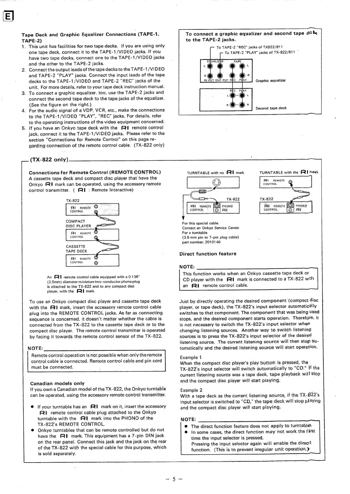
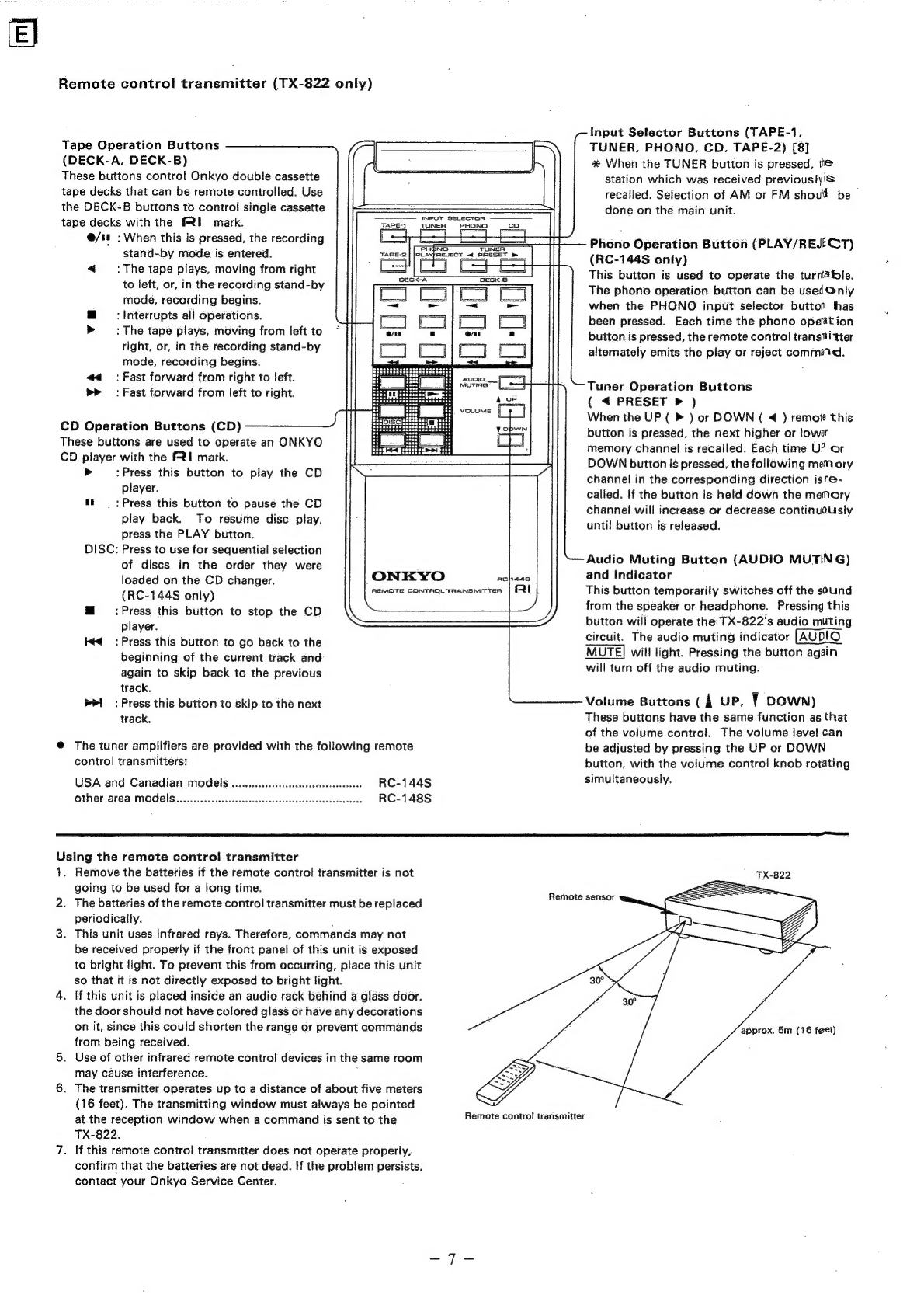
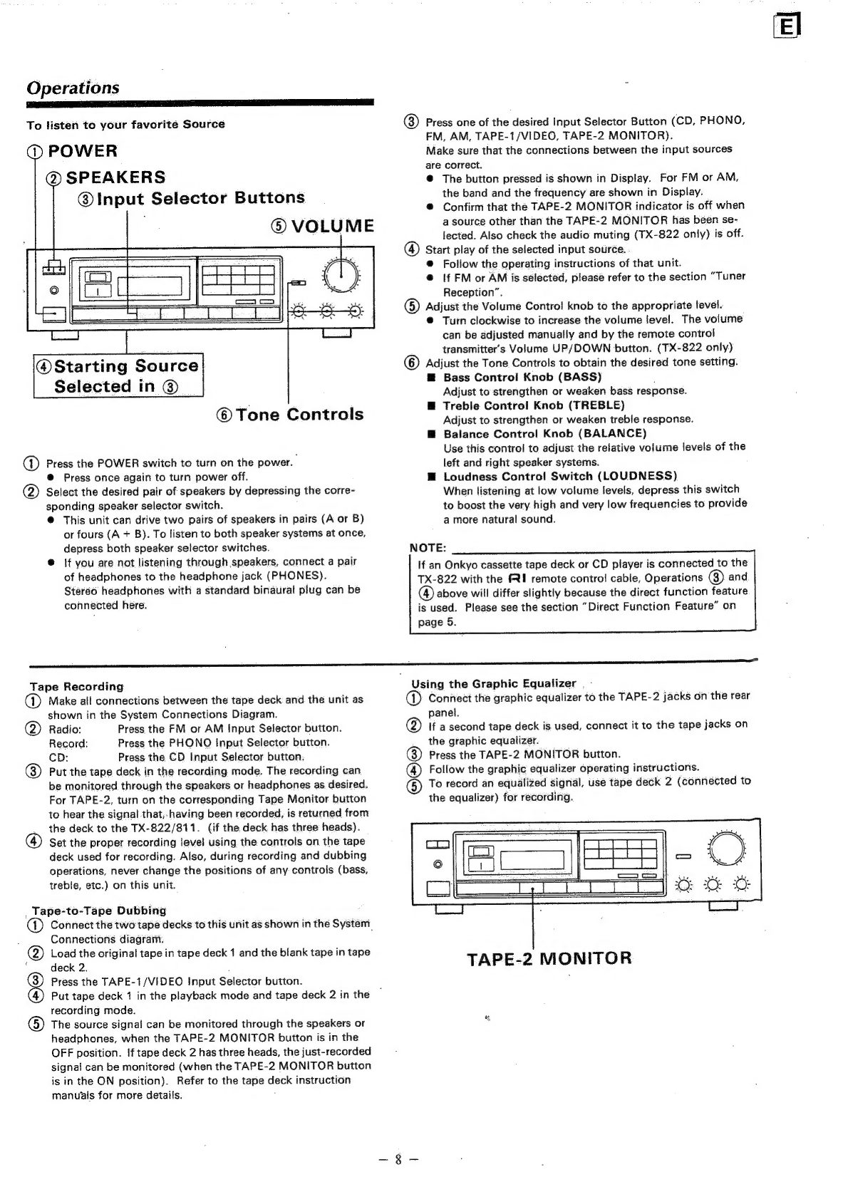
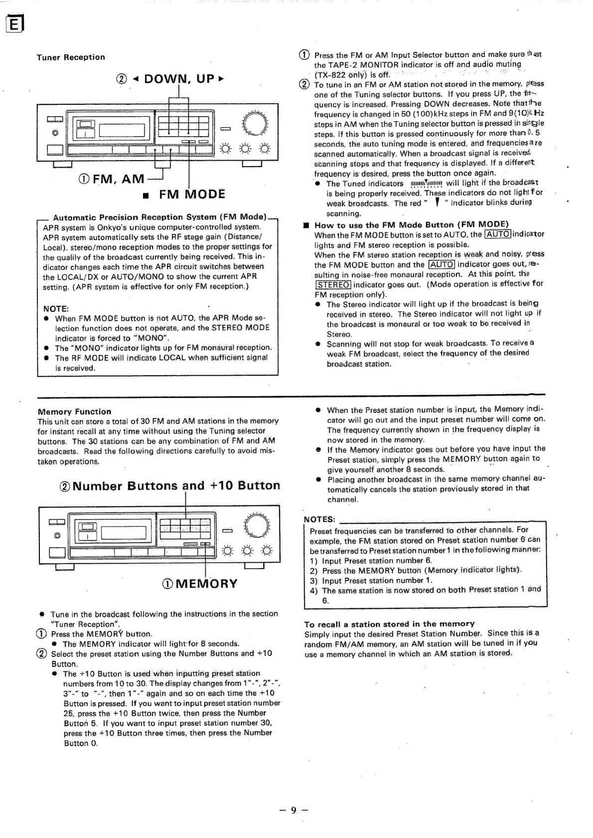
Onkyo TX-822 User manual

Artistry
in
Sound
ON
13340)
X-82
Quartz
Synthesized
Tuner
Amplifier
—
Quarz-Synthesizer-Empfanger-Verstarker
Ampli-tuner
a
synthétiseur
a
quartz
Amplificador-sintonizador
sintetizado
por
cuarzo
Quartz-Synthesizer-Tuner-Versterker
|
Quartz
syntestuner/forstarkare
Amplificatore
sintanizzatore/sintetizzato
¢
al
quarzo

e
Congratulations
on
your
pulehwse
of
the
ONK’
¥O
TX-
622,
1X
87
1
Tuner-Amplitier.
©
Please
read
this
manual
thoroughly
before
making
connections
and
turning
‘power
on.
e
Following
the
instructions
in
this
manual
will
enable
you
to
obtain
optimum
performanc
eC
and
listening
enjoyment
from
your
new
TX-822,
7X.
-81
7.
@
Please
retain
this
penual
for
future.
:
;
reference.
:
:
pate
CONTENTS
Features
Be
ahamianet
Important
safeQguards.............
cesses
eeestetetesseeeseees
ot
seal
PLECAUTIONS
...........ccccceceseesessssssteeeenesseseseneetarsessencuseeseneneodies
ee
Before
using
this
UNlit...........
eee
teeeeeeeeennenetes
Oeecarser
System
CONNECTIONS
«0.0...
eccsssessseessssescssesessesessnecsennnesennnansenneess
Control
positions
and
names
Operations.......ccccccecscssssssssescsccsesssseenesssenssesneeneceeesseneeeesesseesseneeeeseneeeeeeesenseseeAneeeeneeesseeeseee
tees
ee
AtAeAeSU
SAU
EGG
RTECS
E
ORE
AE
Troubleshooting
guide
Specifications
.:
:
Features
a
ee
aa
@
Plenty
of
clean
Power
TX-822:
40
watts
of
continuous
power
per
channel
into
8
ohms
with
no
more
than
0.3%
total
harmonic
distortion
(2.x
50
watts
continuous
power
at
4
ohms
DIN)
Canadian
model:
50
watts
of
continuous
power
per
channel
into
8
ohms
with
no
more
than
0.
3%
total
harmonic
distortion
(2
x
90
watts
dynamic
power
at
4
ohms)
TX-811:
40
watts
of
continuous.
power
per
channel
into
8
ohms
with
no
more
thai
0.3%
total
harmonic
distortion
ie)
x
50
watis
continuous
power
at
4
ohms
DIN)
@
Six
Program
Inputs
Including
Video
Sound
with
Logic
Controlled
Father:
Touch
Keys
°°
The
TX-822
and
TX-811
can
both
handle
six
input
sources:
FM,
AM,
phono,
CD
player,
tape-1/video
and
tape-2.
This
gives
you
plenty
of
flexibility
as
well
as
the
chance
to
expand
your
system
in
future.
The
logic
controlled
feather
touch
keys
make
for
smooth
switching
between
sources.
@
APR.
(Automatic
Precision
Reception)
System
Onkyo’s
exclusive
APR
system
lets
every:FM
broadcast
Sound
its
best.
It
constantly
monitors
the
signal
and
sélects
the
optimum
|
settings
for
two
reception
modes:
RF
local/DX
and
stereo
auto/mono.
The
APR
system
settings
are
shown
by
indicators
on
the
front
panel.
@
Multi-Function
Infrared
Remote
Control
Included
(TX-
-822).
:
The
included
remote
contro!
covers
all
of
the
TX-822’s
major
functions
including
volume
up/down,
‘audio
muting,
tuner
preset
station
channel
and
input
selector
switching.
It
can
also
contro!
the
major
functions
of
any
Onkyo
cassette
deck
or
CD
player
bearing
the
fRE
mark
after
you
make
the
appropriate
connections
with
the
TX-822:
:
@
30-Station
FM/AM
Random
Preset
Tuning
The
TX-822
and
TX-811
let
you
store
thirty
AM
and
FM
stations
in
memory
in
any
combination.
Avid
FM
fans
can
devote
most
or
all
of
the
memory
settings
to
FM
stations.
If
there
are
few
FM
stations
in
your
area,
simply
register
more
AM
stations
in
memory.
,
@
Two
Pairs
of
Speaker
Output
Terminals
e
Battery-Free
Backup
System
to
Protect
Memory
Contents
Important
safeguards
SE
IT
SEE
OE
oR
“WARNING”
ATTENTION
FOR
BRITISH
MODEL
“TO
REDUCE
THE
RISK
OF
FIRE
OR
ELECTRIC
SHOCK,
DO
NOT
®
Replacement
arid
mounting
of
an
AC
plug
on
the
power
supply
EXPOSE
THIS
APPLIANCE
TO
RAIN
OR
MOISTURE.”
cord
of
this
unit
should,
be
B
harlonnied
ol
v.
by
qualthied
service
personnel:
S
:
"
ghee
CAUTION
@
IMPORTANT:
The
wires
in
e@
mains
fase!
are
coloured
in
ac-
“TO
REDUCE
THE
RISK
OF
ELECTRIC
SHOCK,
DONOT
REMOVE
-
cordance
wi
pe
TOS
Be
ga
the
following
COVER
(OR
BACK).
NO
USER-SERVICEABLE
PARTS
INSIDE.
Bius:
~°
Neutral
REFER
SERVICING
TO
QUALIFIED
SERVICE
PERSONNEL.”
pak
Browns
.2<..
Live,
-
Ee
By
es
’ q :
As
thé
colours
of
the
wires
in
the
mains
lead
of
this
apparatus
may
@
4
Eo
megs
DaNnS
pewel
cord.
witha
polarized
plug,
not
correspond
with
the
coloured
markings
identifying
tt
the
terminals
CAUTION:
To
PREVENT
ELECTRIC
SHOCK
DO
NOT
USE
in,
your
plug,
proceed
as
follows:
THIS
(POLARIZED)
PLUG
WITH
AN
EXTENSION
CORD,
RE-
The
wire:
which
is
colotited
blue
must
be
éurinected
to
‘the
terminal
CEPTACLE
OR
OTHER
OUTLET
UNLESS
THE
BLADES
CAN
BE
_
.,
Which
is
marked
withthe
letter
N
or
coloured
plack.c:
éh
is
coloured
brown
must
be
connected
i
Ahetoriinal
_
which
is
marked
With
the
letter
Lo
coloured
red:
:
®@
This
apparatus
complies:
with
requirements
of
EC
directive
87/
308/EEC.
FULLY
INSERTED
TO
PREVENT
BLADE
EXPOSURE.

Observe
the
following
precautions
to
obtain
troublefree
performance
for
many
years.
1.
Avoid
places
subject
to
direct
sunlight
or
extremely
high
or
low
temperatures.
_
Avoid
damp
or
dusty
places
and
places
directly
affected
by
vibrations
from
the
speakérs.
In
particular,
avoid
placing
thé
unit
on
or
above
one
of
the
speakers.
_
Avoid
unstable
focations
and
high
places
from
which
the
unit
could
fall.
_
Ventilation
—
The
unit
should
be
situated
so
that
its
location
or
position
does
not
interfere
with
proper
ventilation.
For
ex-
ample,
the
unit
should
not
be
placed
on
a
bed,
sofa,
rug
of
similar
surface
that
could
block
the
ventilation
openings
or
placed
in
a
built-in
installation,
such
as
a
bookcase
or
cabinet,
that
could
impede
the
flow
of
air
through
the
ventilation
openings.
.
Heat
—
The
unit
should
be
situated
away
from
heat
sources
such
as
radiators,
heat
registers,
or
other
appliances
(including
amplifiers)
that
produce
heat.
Precautions
AR
I
OE,
1.
Warranty
Card
The
serial
number
is
written
on
the
rear
panel
of
this
unit.
Copy
the
serial
number
and
model
number
onto
your
warranty
card
and
keep
it
in
a
safe
place.
.
Recording
Copyright
Recording
of
copyrighted
material
for
other
than
personal
use
is
iNegal
without
permission
of
the
copyright
holder.
.
AC
Fuse
The
fuse
is
located
inside
the
chassis
and
is
not
user
serviceable.
if
power
does
not
come
on,
contact
your
Onkyo
service
center.
.
Care
From
time
to
time
you
should
wipe
off
the
front
and
rear
panels
and
the
cabinet
with
a
soft
cloth.
For
heavier
dirt,
dampen
a
soft
cloth
in
a
weak
solution
of
mild
detergent
and
water,
wring
it
out
dry,
and
wipe
off
the
dirt.
Following
this,
dry
immediately
with
a
clean
cloth.
Do
not
use
rough
material,
thinners,
alcohol
or
other
chemical
solvents
or
cloths
since
these
could
damage
the
finish
or
remove
the
panel
lettering.
.
Power
WARNING
BEFORE
TURNING
ON
POWER
FOR THE
FIRST
TIME,
READ
THE
FOLLOWING
SECTION
CAREFULLY.
Some
models
are
designed
for
use
only
with
the
power
supply
voltage
of
the
region
where
they
are
sold.
European
modeis
(except
U.K.):
Canadian
models:
U.K.
&
Australian
models:
Worldwide
models:
AC220V,
50Hz
AC120V,
60Hz
AC
240V,
50Hz
120
and
220V
switchable,
50/60Hz
®
Voltage
Selector
(Rear
Panel)
Worldwide
models
are
equipped
with
a
voltage
selector
to
__
cénforrn
with
local
power
supplies.
Be
sure
to
set
this
switch
to
match
the
voltage
of
the
power
supply
in
your
area
before
turriing
the
power
switch
on.
Voltage
is
changed.
by
sliding
the
groove
in
the
switch
with
a
screwdriver
to
the
right
or
left.
Confirm
that
the
switch
has
been
moved
all
the
way
to
the
right
or
left
before
turnifig
the
power
switch
on.
Models
without
a
voltage
selector
can
only
be
used
in
areas
where
the
power
supply
is
the
same
as
that
of
the
unit.
@
Tuning
Step
Frequency
Switch
(Bottom)
6.
Cleaning
of
the
internal
parts
should
be
performed
only
by
qualified
service
personnel...
7.
Spillage
—
Care
should
be
taken
so
that
objects
do
not
fall
and
liquids
are
not
spilled
into
the
enclosure
through
the
openings.
8.
Damage
Requiring
Service
~
The
unit
should
be
serviced
by
qualified
service
personne!
when:
A.
The
power
supply.
cord
or
the
plug
has
been
damaged;
or
B.
Objects
have
fallen
or
liquid
has
been
spilled
into
the
unit;
or
a
C.
The
unit
has
been
exposed
to
rain;
or
D.
The
unit
does
not
appear
to
operate
normally
or
exhibits
a
marked
change
in
performance;
or
;
E.
The
unit
has
been
dropped
or
the
enclosure
damaged:
9.
Servicing
—
The
user
should
not
attempt
to
service
the
unit
beyond
that
described
in
the
operating
instructions.
All
other
servicing
should
be
referred
to
qualified
service
personnel.
CH
220V
™
at
AC220V
220V
120V™
120V
at
AC120V
Worldwide
models
are
equipped
with
a
switch
that
controls
the
AM
(9kHz/10kHz)
and
FM
(50kHz/100kHz)
band
tuning
steps.
Be
sure
to
set
this
switch
to
match
the
tuning
step
frequency
in
your
area.
;
U.S.A.
and
Canada
10kH2/100kHz
Other
area
9kHz/50kHz
Memory
Preservation
This
unit
does
not
require
memory
preservation
batteries.
Avw:
built-in
memory
power
back-up
system
preserves
the
contents
;
of
the
memory
during
power
failures
and
even
when
the
unit
is
unplugged.
The
unit
must
be
plugged
in
and
the
power
switch
turned
on
and
off
once
in
order
to
charge
the
back-up
system.
Note
that
since
this
is
not’a
permanent
memory,
the
power
switch
must
be
turned
on
and
off
a
few
times
each
month
to
keep
the
back-up
system
operative.
The
memory
preservation
périod
after
power
has
been
turned
off
varies
depending
on
climate
and
placement
of
the
unit.
On
the
average,
memory
contents
are
protected
over
a
period
of
a
few.
weeks
after
the
last
time
power
has
been
turned
off.
This
périod
is
shorter
when
the
uhit
is
exposed
to.a
highly
humid
climate.

Before
using
this
unit
1.
Supplied
Accessories
T-shaped
FM
antenna
X
4
AM
loop
antenna
x
1
Precautions
when
using
batteries
®
The
remote
control
transmitter
is
powered
by
two
batteries.
Before
using
this.
unit
for
the
first
time,.insert
the
two
batteries
(included)
as
shown
in
the
diagram.
.
®
Average
battery
life
is
about
one
year.
This
period
may
be
shorter
depending
on
the
frequency
of
use
and
environment
(temper-
ature
and
humidity)
in
which
the
remote
control
transmitter
is
used.
System
connections
.
mE
EOE
NE
ORL
TONES
I
CL
FM
Antenna
Connections
Use
the
T-shaped
antenna
if
you
live
in
an
area
where
signal
strength
of
FM
broadcasts
is.
high.
Connect
the
antenna
to.
the
FM
75
ohms
terminals
and
place
the
antenna
on.a
wall
or
other
surface
in
the
position
in
which
reception
is
best.
If
signal
strength
is
fow
in
your
area,
use
a
multi-element
FM
outdoor
antenna.
Consult
your
Onkyo
authorized
service
center
about
the
right
type
of
antenna
for
your
area,
NOTES:
é
ze
oa
1.
Do.
not
connect
both
the
indoor
T-shaped
antenna
and
an
outdoor
FM
antenna.
If
you
decide
to
install
an
outdoor.
antenna,
be
sure
to
disconnect
the
indoor
T-shaped
antenna.
2.
Do
not
use
the
same
antenna
for
both
FM
and
TV
reception
since
the
FM
and
TV
signals
can
interfere
with
each
other.
If
you
must
use
a
common
FM/TV
antenna,
use
a
directional
linkage
type
splitter.
Directional
linkage
type
splitter
To
receiver
To
TV
(or
VCR)
TX-822
only
RI
remote
contro!
cable
x
1.
Remote
control
transmitter
xt
Batteries
x
2
©
|f
the
remote
control
transmitter
does
not
operate
even
thou
gh
front
pariel
coritrols
function
normally,
the
batteries
should
be
replaced.
Usé
only
batteries
listed
in
the
following
chart,
.
Do
not
leave
an
expired
battery
in
the
case
as
it
may
leak
or
damage
the
battery
case.
.
When
inserting
the
batteries,
be
sure
the
(+)
and
(—)
ends
ate
properly
aligned.
.
Do
not
use
nickel-cadmium
(rechargeable)
batteries.
.
Do
not
use
one
specified
(manganese)
battery
and
one
dl-
kaline
Battery
at
the
same
timé.
.
Replace
both
batteries
at
once;
do
not
use
one
old
and
one
new
battery
together.
AM
Joop
antenna
assembly
Connect.to
the
AM
antenna
terminals.
®
Remove
the
vinyl
tie
and.
take
out
the
connection
line.
Bend
in
the
reverse
direction.
a.
With
the
antenna
on
top
of
any
stable
surface:
b.
With
the
antenna
attached
to
a
wall
Installation
hole
Mount
on
a
wall,
etc.

Do
not
connect
both
indoor
and
outdoor
FM
antennas.
If
you
decide
to.
install
an
outdoor
antenna,
be
sure
to
disconnect
the
indoor
feeder
antenna.
AM
toop
anterina
Models
for
some
areas
are
equipped
with
a
screw-type
FM
antenna
terminal
(75/300
ohms).
indoor
T-shaped
antenna
Outdoor
FM
Antenna
PHONO
CD
TAPEA/VIDEO
TAPE.2
Outdoor
AM
antenna
TX-822
only
General
Switch
the
main
power
switch
off
before
performing
connections.
Also
be
sure
to
perform
left
and
right
channel
connections
properly.
>
Twist
SPEAKER
(A)
R
Lk.
Ollo
Lift
the
lever
and
insert
the
wire.
When
the
wire
has
been
inserted
firmly
into
the
hole,
release
the
lever.
i
AUGLTAGE
SELECTORS,
_
Worldwide
models
only
ANTENNA
GND
\
N
N
x
\
s
|
XN
Ground
connection
is
not
s
necessary
for
turntable
without
ground
fead
‘
i)
'
i}
'
1
4
1
1
t
1
i}
og
|
veers
iy
/
REMOTE
a
L
CONTROL
F
1
i
A
y
y
R
@)
|
a
oo
:
1
3
al
TUNE
8
{|
4
i
8
MODEL
NO.
—_
I:
RATING
—
=
ONH¥O
CORPORATION
NADE
IN
JEPAN
AC
POWER
SUPPLY
CORD
O O
L
t L
R
R R
&
C)
SPEAKER
IMPEDANCE:
baal
ee
;
4
ohms
MIN./speaker
TURNTABLE
COMPACT
CASSETTE
TAPE
CASSETTE
TAPE
R
8
ohms
MIN./speaker
DISC
DECK
1
DECK
2
SPEAKER
(B)
(Canadian
mode!)
PLAYER
or
or
GRAPHIC
VIDEO
CASSETTE
EQUALIZER
RECORDER
AM
Antenna.
Connections
An
AM
loop
antenna
is
included
in
the
installation
instructions
bag.
Take
out
the
connection
line
and
connect
it
to
the
AM
antenna
terminals.
Thi§
loop
antenna
can
be
placed
on
top
of
any
stable
surface
or
attached
to
a
wall.
Try
séveral
positions
to
determine
which
gives.
the
best
reception.
Be
sure
the
antenna
is
not
near
a
speaker,
power
cord,
television
set,
VCR,
or
motorized
appliances:
When
using
an
external
AM
antenna,
do
not
remove
the
loop
an-
tenna;
connect
both
antennas
to
the
AM
antenna
terminals.
NOTE:
onde
_
AM
reception
is
easily
affected
by
television
sets
and
VCRs.
Therefore,
AM
reception
may
be
poor
if
this
unit
is
placed
too
close
to
a
TV
or
a
VCR,
Speaker
Connections
(SPEAKERS)
“4.
Connect
the
spéakers
to
A
and/or
B
terminals.
2.
When
connecting
speakers,
proper
polarity
is
important.
Always
connect
the
(+)
terminal
(red)
on
this
equipment
to
the
(+)
terminal
on
the
speaker
and
the
(—)
terminal
(black)
on
this
equipment
to
the
(—)
terminal
on
the
speaker.
3.
Do
not
connect
a
single
speaker
in
parallel
to
the
right
and
left
channel
outputs.
4.
Use
speaker
cables
that
have
a
low
inipedaricé
and
that
are
as
short
as
possible.
*
Attach
speaker
cables
to
the
rear
panel
speaker
terminals
with
care,
being
sure
that
connections
are
made
firmly
and
that
there
is
No
possibility
of
a
short
circuit
occurring.
‘NOTE:
When
both
the
Aand
B
Speaker
Selector
switches
are
dapieseed,
the
A
and
B
speaker
systems
operate
in
a
series
connection.
If
only
one
pair
of
speakers
is
connected,
no
sound
at
all
will
be
heard.
Compact
Disc
Player
or
Other
Component
Connections
(CD)
Connect
the
output
leads
of
the
CD
player
or
an
additional
audio
component
to
the
CD
jacks.
An
Onkyo
CD
player
with
remote
contro!
that
has
the
(I
mark
can
be
operated
by
the
TX-822.
(Please
refer
to
“Connections
for
Remote
Control”
on
page
5.)
For
more
details,
refer
to
your
CD
player
instruction
manual.
Turntable
Connections
(PHONO)
Connect
the
output
leads
of
the
turntable
to
the
PHONO
jacks.
Bé
sure
to
connect
the
ground
(earth)
lead
wire
from
the
turntable
to
the
ground
terminal
(GND)
(Antenna
terminal).
Lack
of
proper
ground
connection
will
cause
hum.
Turntables
not
provided
with
GND
wires
do
not
need
to
be
connected.
1.
Place
the
turntable
on
a
firm
shelf
or
deck
free
from
vibrations
(especially
those
generated
by
the
speaker
system).
If
the
turntable
is
permitted
to
pick
up
such
unwanted
vibrations,
not
only
with
the
performance
of
the
unit
drop,
but
distortion
in
the
bass
frequencies
and
howling
in
the
speakers
may
also.
occur.
2.
Check
the
turntable
instruction
manual
for
any
other
precaution
s.
3.
The
loud
noises
that
occur
when
connecting
and
disconnecting
~
the
turntable
leads,
replacing
the
cartridge
or
lowering
the
tonearm
could
damage
the
speakers.
Always
turn
the
power
switch
off
before
making
connections.

Tape
Deck
and
Graphic
Equalizer
Connections
(EAEE:
-1,
TAPE-2)
1.
This
unit
has
facilities
for
two
tape
decks.
If
you
are
using
only
one
tape
deck,
connect
it
to
the
TAPE-1/VIDEO
jacks.
If
you
have
two
tape
decks,
connect
one
to
the
TAPE-1/VIDEO
jacks
and
the
other
to
the
TAPE-2
jacks.
.
Connect
the
output
leads
of
the
tape
decks
to
the
TAPE-1/VIDEO
and
TAPE-2
“PLAY”
jacks.
Connect
the
input
leads
of
the
tape
decks
to
the
TAPE-1/VIDEO
and
TAPE-2
“REC”
jacks
of
the
unit.
For
more
details,
refer
to
your
tape
deck
instruction
manual.
.
To
connect
a
graphic
equalizer,
too,
use
the
TAPE-2
jacks
and
connect
the
second
tape
deck
to
the
tape
jacks
of
the
equalizer.
(See
the
figure
on
the
right.)
For the
audio
signal
of
a
VDP,
VCR,
etc.,
make
the
connections
to
the
TAPE-1/VIDEO
“PLAY”,
“REC”
jacks.
For
details,
refer
to
the
operating
instructions
of
the
video
equipment
concerned.
.
If
you
have
an
Onkyo
tape
deck
with
the
fQI
remote
control
jack,
connect
it
to
the
TAPE-1/VIDEO
jacks.
Please
refer
to
the
section
“Connections
for
Remote
Control”
on
this
page
re-
garding
connection
of
the
remote
control
cable.
(TX-822
only)
(TX-822
only)
Connections
for
Remote
Control
(REMOTE
CONTROL)
A
cassette
tape
deck
and
compact
disc
player
that
have
the
Onkyo
fi
mark
can
be
operated,
using
the
accessory
remote
control
transmitter.
(
(RE:
Remote
Interactive)
TX-822
FI
REMOTE
(Om
CONTROL
COMPACT
DISC
PLAYER
FRI
REMOTE
CONTROL
CASSETTE
TAPE
DECK
£
REMOTE
©
Dace
An
§RE
remote
control
cable
equipped
with
a
0.136”
(3.5mm)
diameter
miniature
two-conductor
phone
plug
is
attached
to
the
TX-822
and
to
any
compact
disc
player,
with
the
f-3—
mark.
To
use
an
Onkyo
compact
disc
player
and
cassette
tape
deck
with
the
f1
mark,
insert
the
accessory
remote
contro!
cable
plug
into
the
REMOTE
CONTROL
jacks.
As
far
as
connecting
sequence
is
concerned,
it
doesn’t
matter
whether
the
cable
is
connected
from
the
TX-822
to
the
cassette
tape
deck
or
to
the
compact
disc
player:
The
remote
control
transmitter
is
operated
by
facing
it
towards
the
remote
control
sensor
of
the
TX-822.
NOTE:
Remote
control
operation
is
not
possible
when
only
the
remote
control
cable
is
connected.
Remote
control
cable
and
pin
cord
must
be
connected.
Canadian
models
only
if
you
own
a
Canadian
model
of
the
TX-822,
the
Onkyo
turntable
can
be
operated,
using
the
accessory
remote
control
transmitter.
®
{ff
your
turntable
has
an
fQ1_
mark
on
it,
insert
the
accessory
fR1
remote
control
cable
plug
attached
to
the
Onkyo
turntable
with
the
FRE
mark
into
the
PHONO
of
the
TX-822's
REMOTE
CONTROL.
@
Onkyo
turntables
that
can
be
remote
controlled
but
do
not
have
the
RI
mark.
This
equipment
has
a
7-pin
DIN
jack
on
the
rear
panel.
Connect
this
jack
and
the
jack
on
the
rear
of
the
TX-822
with
the
special
cable
for
this
purpose,
which
is
sold
separately.
To
connect
a
graphic
equalizer
and
second
tape
dec
by
to
the
TAPE-2
jacks.
To
TAPE-2
“REC”
jacks
of
TX822/811
To-TAPE-2
“PLAY”
jacks
of
TX-822/811
~
Graphic
equalizer
Second
tape
deck
TURNTABLE
with
the
FR
EP
mark
TURNTABLE
with
no
FRE
mark
fo.
&
FRI
REMOTE
202
|
CONTROL
%
i
nemore
RON
cHone:
CONTROL
RIE
|
Ce
TX-822
i
remote
KON
prone
CONTROL
RI
For
this
special
cable.
Contact
an
Onkyo
Service
Center.
For
a
turntable
(3.5
mm
pin
to
7-pin
plug
cable)
part
number;
2010140
TX-822
Direct
function
feature
NOTE:
This
function
works
when
an
Onkyo
cassette
tape
deck
or
CD
player
with
the
FRI
mark
is
connected
to
a
TX-822
with
an
fR1
remote
control
cable.
Just
by
directly
operating
the
desired
component
(compact
disc
player,
or
tape
deck),
the
TX-822’s
input
selector
automatically
switches
to
that
component.
The
component
that
was
being
used
stops,
and
the
desired
component
starts
operation.
Therefofe;
it
is
not
necessary
to
switch
the
TX-822’s
input
selector
when
changing
listening
sources.
Another
way
to.
switch
listening
sources
is
to
press
the
TX-822’s
input
selector
of
the
desired
listening
source.
The
current
listening
source
will
then
stop
au-
tomatically
and
the
desired
listening
source
will
start
operation.
Example
1
When
the
compact
disé
player's
play
button
is
pressed,
the
TX-822’s
input
selector
will
switch
automatically
to
“CD.”
if
the
current
listening
source
was
a
tape
deck,
tape
playback
will
Stop
and
the
compact
disc
player
will
start
playing.
Example
2
With
a
tape
deck
as
the
current
listening
source,
if
the
TX-822’s
input
selector
is
switched
to
“CD,”
the
tape
deck
will
stop
playing
and
the
compact
disc
player
will
start
playing.
NOTE:
@
The
direct
function
fasnue
dogs
not
apply
to
turntable.
@
|nsome
cases,
the
direct
function
may
not
work
the
f#tst
time
the
input
selector
is
pressed.
Pressing
the
input
selector
again
will
enable
the
direct
function.
(This
is
to
prevent
irregular
unit
operation.»

Front
panel
For
more
information
about
buttons
or
controls,
turn
to
the
page
number
listed
in
the
[
Headphone
Jack
(PHONES)
Remote
Control
Sensor
(REMOTE
SENSOR)
[7]
(TX-822
only)
Control
positions
and
names
Speaker
Selector
Switches
(SPEAKERS)
[8]
FM
APR
Indicators
ONEVO
ovaisz
synitiiesizeo
TUNER
AMPLIFIER,
RIT
»
@
The
features,
specifications,
and
display
for
the
TX-822
and
TX-811
are
slightly
different.
Read
this
manual
carefully
to
operate
the
model
you
have
purchased
correctly.
Number
Buttons
and
+10
Button
(1~9,
0,
+10)[9]
Memory
Button
(MEMORY){9]
Loudness
Control!
Switch
(LOUDNESS)[8]
Volume
Control
Knob
(VOLUME)[8]
Tuning
Selector
Buttons
(
<
DOWN,
UP
P
)
[9]
Power
Switch
(POWER)
[8]
Display
and
indicators
Memory
indicator
INPUT
SELECTOR
=
Input
Selector
Buttons
(TAPE-2
MONITOR,
TAPE-1/VIDEO,
AM,
FM,
PHONO,
CD)
[8]
Audio
Muting
Indicator
(TX=822
only)
Tape-2
Monitor
Indicator
Input
Selector/Preset
Station
Display
ave
iro
|
ant
ioe
FM
Mode
Button
(FM
MODE)
[9]
Bass
Control!
Knob
(BASS)
[8]
Treble
Control
Knob
(TREBLE)
[8]
Balance
Control
Knob
(BALANCE)
[8]
FM
Stereo
Indicator
FM
Mode
Indicator
Tuned
Indicators
Frequency
Display

Remote
control
transmitter
(TX-822
only)
Tape
Operation
Buttons
(DECK-A,
DECK-B)
These
buttons
control
Onkyo
double
cassette
tape
decks
that
can
be
remote
controlled.
Use
the
DECK-B
buttons
to
control
single
cassette
tape
decks
with
the
FRI
mark.
CD
Operation
Buttons
(CD)
These
buttons
are
used
to
operate
an
ONKYO
CD
player
with
the
(RI
mark.
TAPE-1
INFUT
SELECTOR
TUNER
PHONO
@/ts
:
When
this
is
pressed,
the
recording
stand-by
mode
is
entered.
<
=:
The
tape
plays,
moving
from
right
to
left,
or,
in
the
recording
stand-by
mode,
recording
begins.
@
=:
interrupts
all
operations.
»
:The
tape
plays,
moving
from
left
to
right,
or,
in
the
recording
stand-by
mode,
recording
begins.
<=:
Fast
forward
from
right
to
left.
>>
:
Fast
forward
from
left
to
right.
>
:Press
this
button
to
play
the
CD
player.
1!
=:
Press
this
button
to
pause
the
CD
play
back.
To
resume
disc
play,
press
the
PLAY
button.
DISC:
Press
to
use
for
sequential
selection
of
discs
in
the
order
they
were
loaded
on
the
CD
changer.
(RC-144S
only)
@
Press
this
button
to
stop
the
CD
player.
4
:
Press
this
button
to
go
back
to
the
beginning
of
the
current
track
and
again
to
skip
back
to
the
previous
track.
>i:
Press
this
button
to
skip
to
the
next
track.
The
tuner
amplifiers
are
provided
with
the
following
remote
control
transmitters:
USA
and
Canadian
models
Other
area
MOdEIS.......
eee
eee
ceneeeesteesesteeensseeteeresee
RC-144S
RC-148S
ONKYO
ma
REMOTE
CONTROL
TRANSMITTER
Input
Selector
Buttons
(TAPE-1,
TUNER,
PHONO,
CD.
TAPE-2)
[8]
%
When
the
TUNER
button
is
pressed,
te
station
which
was
received
previouslyiS
recalled.
Selection
of
AM
or
FM
should
be
done
on
the
main
unit.
Phono
Operation
Button
(PLAY/REJECT)
(RC-144S
only)
This
button
is
used
to
operate
the
turnlable.
The
phono
operation
button
can
be
used
Only
when
the
PHONO
input
selector
button
has
been
pressed.
Each
time
the
phono
opelation
button
is
pressed,
the
remote
control
transmitter
alternately
emits
the
play
or
reject
comménd.
Tuner
Operation
Buttons
(
«4
PRESET
P
)
When
the
UP
(
»
)
or
DOWN
(
€
)
remote
this
button
is
pressed,
the
next
higher
or
lower
memory
channel
is
recalled.
Each
time
UP
or
DOWN
button
is
pressed,
the
following
menory
channel
in
the
corresponding
direction
isre-
called.
If
the
button
is
held
down
the
memory
channel
will
increase
or
decrease
continuously
until
button
is
released.
Audio
Muting
Button
(AUDIO
MUTING)
and
Indicator
This
button
temporarily
switches
off
the
sound
from
the
speaker
or
headphone.
Pressing
this
button
will
operate
the
TX-822's
audio
muting
circuit.
The
audio
muting
indicator
[AUDIO
MUTE|
will
light.
Pressing
the
button
again
will
turn
off
the
audio
muting.
Volume
Buttons
(4
uP,
7
Down)
These
buttons
have
the
same
function
as
that
of
the
volume
control.
The
volume
level
can
be
adjusted
by
pressing
the
UP
or
DOWN
button,
with
the
volume
control
knob
rotating
simultaneously.
Using
the
remote
control
transmitter
1.
2.
Remove
the
batteries
if
the
remote
control
transmitter
is
not
going
to
be
used
for
a
long
time.
The
batteries
of
the
remote
control
transmitter
must
be
replaced
periodically.
This
unit
uses
infrared
rays.
Therefore,
commands
may
not
be
received
properly
if
the
front
panel
of
this
unit
is
exposed
to
bright
light.
To
prevent
this
from
occurring,
place
this
unit
so
that
it
is
not
directly
exposed
to
bright
fight.
.
tf
this
unit
is
placed
inside
an
audio
rack
behind
a
glass
door,
the
door
should
not
have
colored
glass
or
have
any
decorations
on
it,
since
this
could
shorten
the
range
or
prevent
commands
from
being
received.
.
Use
of
other
infrared
remote
control
devices
in
the
same
room
may
cause
interference.
.
The
transmitter
operates
up
to
a
distance
of
about
five
meters
(16
feet).
The
transmitting
window
must
always
be
pointed
at
the
reception
window
when
a
command
is
sent
to
the
TX-822.
.
lf
this
remote
control
transmitter
does
not
operate
properly,
confirm
that
the
batteries
are
not
dead.
If
the
problem
persists,
contact
your
Onkyo
Service
Center.
Remote
sensor
approx.
5m
(16
feet)
Remote
control
transmitter

Operations
Perr
SSE
Soe
IQA
eS EE
Tee
ORE
i
eae
a
he
aes
|
To
listen
to
your
favorite
Source
@Q
POWER
@
SPEAKERS
@ItInput
Selector
Buttons
@©
VOLUME
@
Starting
Source
Selected
in
@
©
Tone
Controls
@
Press
the
POWER
switch
to
turn
on
the
power.
@
Press
once
again
to
turn
power
off.
@)
Select
the
desired
pair
of
speakers
by
depressing
the
corre-
sponding
speaker
selector
switch.
@
This
unit
can
drive
two
pairs
of
speakers
in
pairs
(A
or
B)
or
fours
(A
+
B).
To
listen
to
both
speaker
systems
at
once,
depress
both
speaker
selector
switches.
©
If
you
are
not
listening
through
speakers,
connect
a
pair
of
headphones
to
the
headphone
jack
(PHONES).
Steréo
headphones
with
a
standard
binaural
plug
can
be
connected
here.
@
Press
one
of
the
desired
Input
Selector
Button
(CD,
PHONO,
FM,
AM,
TAPE-1/VIDEO,
TAPE-2
MONITOR).
Make
sure
that
the
connections
between
the
input
sources
are
correct.
@
The
button
pressed
is
shown
in
Display.
For
FM
or
AM,
the
band
and
the
frequency
are
shown
in
Display.
®@
Confirm
that
the
TAPE-2
MONITOR
indicator
is
off
when
a
source
other
than
the
TAPE-2
MONITOR
has
been
se-
lected.
Also
check
the
audio
muting
(TX-822
only)
is
off.
®
Start
play
of
the
selected
input
source.
®@
Follow
the
operating
instructions
of
that
unit.
@
|f
FM
or
AM
is
selected,
please
refer
to
the
section
“Tuner
Reception”.
6)
Adjust
the
Volume
Contro!
knob
to
the
appropriate
level.
@
Turn
clockwise
to
increase
the
volume
level.
The
volume
can
be
adjusted
manually
and
by
the
remote
control
transmitter’s
Volume
UP/DOWN
button.
(TX-822
only)
®
Adjust
the
Tone
Controls
to
obtain
the
desired
tone
setting.
@
Bass
Control
Knob
(BASS)
:
Adjust
to
strengthen
or
weaken
bass
response.
@
Treble
Control
Knob
(TREBLE)
Adjust
to
strengthen
or
weaken
treble
response.
™@
Balance
Control
Knob
(BALANCE)
Use
this
controi
to
adjust
the
relative
volume
levels
of
the
left
and
right
speaker
systems.
@
Loudness
Control
Switch
(LOUDNESS)
When
listening
at
low
volume
levels,
depress
this
switch
to
boost
the
very
high
and
very
low
frequencies
to
provide
a
more
natural
sound.
NOTE:
If
an
Onkyo
cassette
tape
deck
or
CD
player
is
connected
to
the
TX-822
with
the
FI
remote
contro!
cable,
Operations
(8)
and
®
above
will
differ
slightly
because
the
direct
function
feature
is
used.
Please
see
the
section
’Direct
Function
Feature”
on
page
5.
Tape
Recording
@
Make
all
connections
between
the
tape
deck
and
the
unit
as
shown
in
the
System
Connections
Diagram.
@
Radio:
Press
the
FM
or
AM
Input
Selector
button.
Record:
Press
the
PHONO
Input
Selector
button.
CD:
Press
the
CD
Input
Selector
button.
8)
Put
the
tape
deck
in
the
recording
mode.
The
recording
can
be
monitored
through
the
speakers
or
headphones
as
desired.
For
TAPE-2,
turn
on
the
corresponding
Tape
Monitor
button
to
hear
the
signal
that,-having
been
recorded,
is
returned
from
the
deck
to
the
TX-822/811.
(if
the
deck
has
three
heads).
@)
Set
the
proper
recording
level
using
the
controls
on
the
tape
deck
used
for
recording.
Also,
during
recording
and
dubbing
operations,
never
change
the
positions
of
any
controls
(bass,
treble,
etc.)
on
this
unit.
,
Tape-to-Tape
Dubbing
@
Connect
the
two
tape
decks
to
this
unit
as
shown
in
the
System.
.
Connections
diagram.
@
Load
the
original
tape
in
tape
deck
1
and
the
blank
tape
in
tape
deck
2.
:
Press
the
TAPE-1/VIDEO
Input
Selector
button.
Put
tape
deck
1
in
the
playback
mode
and
tape
deck
2
in
the
recording
mode.
The
source
signal
can
be
monitored
through
the
speakers
or
headphones,
when
the
TAPE-2
MONITOR
button
is
in
the
OFF
position.
!f
tape
deck
2
has
three
heads,
the
just-recorded
signal
can
be
monitored
(when
the
TAPE-2
MONITOR
button
is
in
the
ON
position).
Refer
to
the
tape
deck
instruction
manuais
for
more
details.
:
Using
the
Graphic
Equalizer
| -
@
Connect
the
graphic
equalizer
to
the
TAPE-2
jacks
on
the
rear
panel.
If
a
second
tape
deck
is
used,
connect
it
to
the
tape
jacks
on
the
graphic
equalizer.
Press
the
TAPE-2
MONITOR
button.
Follow
the
graphic
equalizer
operating
instructions.
To
record
an
equalized
signal,
use
tape
deck
2
(connected
to
the
equalizer)
for
recording.
=i)
ca
ce
Oe
Oe
TAPE-2
MONITOR

Tuner
Reception
®
<«
DOWN,
UP>
s
FM
MODE
Automatic
Precision
Reception
System
(FM
Mode)
APR
system
is
Onkyo’s
unique
computer-controlled
system.
APR
system
automatically
sets
the
RF
stage
gain
(Distance/
Local),
stereo/mono
reception
modes
to
the
proper
settings
for
the
qualily
of
the
broadcast
currently
being
received.
This
in-
dicator
changes
each time
the
APR
circuit
switches
between
the
LOCAL/DX
or
AUTO/MONO
to
show
the
current
APR
setting.
(APR
system
is
effective
for
only
FM
reception.)
NOTE:
@
When
FM
MODE
button
is
not
AUTO,
the
APR
Mode
se-
tection
function
does
not
operate,
and
the
STEREO
MODE
indicator
is
forced
to
“MONO”.
®
The
“MONO”
indicator
lights
up
for
FM
monaural
reception.
@
The
RF
MODE
will
indicate
LOCAL
when
sufficient
signal
is
received.
®
Press
the
FM
or
AM
Input
Selector
button
and
make
sure
that
the
TAPE-2
MONITOR
indicator
is
off
and
audio
muting
'
(TX-822
only)
is
off.
@
To
tune
in
an
FM
or
AM
station
not
javedt
in
the
memory,
pi@ss
one
of
the
Tuning
selector
buttons.
If
you
press
UP,
the
fre~
quency
is
increased.
Pressing
DOWN
decreases.
Note
thatthe
frequency
is
changed
in
50
(100)kHz
steps
in
FM
and
9(10)k
Hz
steps
in
AM
when
the
Tuning
selector
button
is
pressed
in
sitgle
steps.
If
this
button
is
pressed
continuously
for
more
than
0.5
seconds,
the
auto
tuning
mode
is
entered,
and
frequencies
are
scanned
automatically.
When
a
broadcast
signal
is
received,
scanning
stops
and
that
frequency
is
displayed.
If
a
different
frequency
is
desired,
press
the
button
once
again.
‘@
The
Tuned
indicators
mum%aninn
will
light
if
the
broadcist
is
being
properly
received.
These
indicators
do
not
light
For
weak
broadcasts.
The
red”
Y
”
indicator
blinks
during
scanning.
M@
How
to
use
the
FM
Mode
Button
(FM
MODE)
When
the
FM
MODE
button
is
set
to
AUTO,
the
[AUTO]indicator
lights
and
FM
stereo
reception
is
possible.
When
the
FM
stereo
station
reception
is
weak
and
noisy,
press
the
FM
MODE
button
and
the
indicator
goes
out,
fe-
sulting
in
noise-free
monaural
reception.
At
this
point,
the
indicator
goes
out.
(Mode
operation
is
effective
for
FM
reception
only).
@
The
Stereo
indicator
will
light
up
if
the
broadcast
is
being
received
in
stereo.
The
Stereo
indicator
will
not
light
up
if
the
broadcast
is
monaural
or
too
weak
to
be
received
in
Stereo.
®@
Scanning
will
not
stop
for
weak
broadcasts.
To
receive
a
weak
FM
broadcast,
select
the
HeAUGHEY
of
the
desired
broadcast
station.
Memory
Function
This
unit
can
store
a
total
of
30
FM
and
AM
stations
in
the
memory
for
instant
recall
at
any
time
without
using
the
Tuning
selector
buttons.
The
30
stations
can
be
any
combination
of
FM
and
AM
broadcasts.
Read
the
following
directions
carefully
to
avoid
mis-
taken
operations.
@
Number
Buttons
and
+10
Button
@®
MEMORY
@
Tune
in
the
broadcast
following
the
instructions.in
the
section
"Tuner
Reception”.
@
Press
the
MEMORY
button.
@®
The
MEMORY
indicator
will
light
for
8
seconds.
@
Select
the
preset
station
using
the
Number
Buttons
and
+10
Button.
@
The
+10
Button
is
used
when
inputtirig
preset
station
numbers
from
10
to
30.
The.
display
changes
from
1”-",
2”-",
-"to
“-”,
then
1”-"
again
and
so
on
each
time
the
+10
Button
is
pressed.
If
you
want
to
input
preset
station
number
25,
press
the
+10
Button
twice,
then
press
the
Number
Button
5.
If
you
want
to
input
preset
station
number
30,
press
the
+10
Button
three
times,
then
press
the
Number
Button
0.
@
When
the
Preset
station
number
is
input,
the
Memory
indi-
cator
will
go
out
and
the
input
preset
number
will
come
on.
The
frequency
currently
shown
in
the
frequency
display
is
now
stored
in
the
memory.
®
If
the
Memory
indicator
goes
out
before
you
have
input
the
Preset
station,
simply
press
the
MEMORY
button
again
to
give
yourself
another
8
seconds.
,
®
Placing
another
broadcast
in
the
same
memory
channel
au-
tomatically
cancels
the
station
previously
stored
in
that
channel.
NOTES:
Preset
frequencies
can
bé
transferred
to
other
channels.
For
example,
the
FM
station
stored
on
Preset
station
number
6
can
be
transferred
to
Preset
station
number
1
in
the
foliowing
manner:
1)
Input
Preset
station
number
6.
2)
Press
the
MEMORY
button
(Memory
indicator
lights).
3)
Input
Preset
station
number
1.
4)
The
same
station
is
now
stored
on
both
Preset
station
1
and
6.
To
recall
a
station
stored
in
the
memory
Simply
input
the
desired
Preset
Station
Number.
Since
this
is.a
random
FM/AM.
memory,
an
AM
station
will
be.tuned
in
if
you
use
a
memory
channel
in
which
an
AM
station
is
stored.

Trouble
shooting
guide
Pr
eds
aD
ae
ee
ER
Ga
eR
ES
aaa
NOTE
(TX-822
only):
lf
a
problem
occurs,
first
operate
the
unit
using
the
front
panel
controls
to
confirm
that
it
is
not
due
to
a
malfunction
(or
worn
out
batteries)
of
the
remote
contro!
transmitter.
No
power.
@
Power
cord
is
disconnected.
@
Connect
power
cord.
:
@
AC
fuse
blown.
@
Contact
Onkyo
Service
Center.
Power
but
no
sound.
@
Tape
monitor
switch
on.
@
Switch
to
off.
@
Audio
muting
switch
on.(TX-822
only)
|
@
Switch
to
off
by
remote
control
transmitter.
®
Bad
connections.
®@
Check
input
leads,
speaker
leads,
pin
plugs,
etc.
®
Amplifier
protection
circuitry
has
been
|
@
Contact
Onkyo
Service
Center.
activated.
Hum,
fow
frequency
noise.
@
Poor
or
no
input
ground.
@
Check
outer
conductor
of
input
plugs.
.
@
Poor
or
no
phono
motor
ground.
@
Check
for
proper
ground
connection.
Howling
when
the
volume
is
turned
up.
|
@
Turntable
and
speakers
are
too
close
@
Move
them
farther
apart.
together.
:
‘
Rough
or
scratchy
sound.
High
range
is
e
Stylus
of
pick-up
is
worn.
®@
Replace.
not
clear.
®
Stylus
tip
is
dirty.
@
Clean.
@
Treble
control
too
high.
@
Turn
treble
control
down.
AM
stations
cannot
be
received.
@
AM
loop
antenna
is
not
attached.
®
Connect
the
included
AM
loop
antenna
to
the
AM
antenna
terminals.
Buzzing
noise
on
AM
(particularly
con-
|
@
Noise
from
electrical
apparatus
such
as
|
@
Move
AM
loop
antenna
to
different
position.
spicuous
at
night
or
with
weak
stations).|
fluorescent
lamp.
®
Set
up
outdoor
AM
antenna.
High
pitched
noise
or
buzzing
noise
on
|
@
Noise
from
TV.
®
Place
the
AM
loop
antenna
as
far
as
possible
from
AM.
the
TV.
@
Move
unit
away
from
TV
set.
Crackling
noise
on
AM
and
FM.
®
Noise
caused
by
turning
fluorescent
@
Move
antenna
as
far
as
possible
from
the
fluores-
}.
lamp
on
and
off.
cent
Jamp.
;
®@
Noise
from
automobile
ignition.
@
Install
and
FM
outdoor
antenna
as
far
as
possible
from
the
road.
®
Change
the
position
or
direction
of
the
outdoor
antenna.
FM
tuned
and
stereo
indicators
light
but
sound
is
distorted
and
stereo
separation
is
bad.
@
Station
is
too
strong.
@
Multiple
reflection
of
the
radio
waves
because
of
tall
buildings
or
mountains.
©
Change
to
T-shaped
antenna.
@
Use
antenna
which
has
better
directivity
and
select
a
point
where
the
distortion
is
least.
FM
tuned
and
stereo
indicators
flicker
®
Station
is
too
weak.
@
Install
an
outdoor
FM
antenna.
on
and
off
and
hiss
is
heard
on
FM.
©
Stereophonic
FM
broadcasts
cover
only|
@
Change
the
position
or
direction
of
the
outdoor
about
half
the
distance
of
an
ordinary
antenna.
;
broadcasts.
~
No
station
is
recalled
when
a
preset
sta-
|
@
The
power
switch
has
not
been
turned
|
@
The
memory
contents
are
lost
if
the
power
switch
tion
number
is
input.
on
for
a
long
time
or
the
power
cord
has|_is
not
turned
on
a
few
times
each
month.
Store
been
unplugged
for
a
long
time.
all
stations
again
and
remember
to-turn
the
power
.
on
a
few
times
each
month.
Front
panel
controls
function
but
remote|
@
No
batteries
in
remote
control
transmit-|
@
insert
batteries.
control
transmitter
does
not.
(TX-822
ter.
®
Replace
batteries.
only)
®
Batteries
have
worn
out.
The
tuning
steps
by
which
the
tuned
frequericy
changes
on
each
band
have
been
set
at
the
factory
to
the
proper
value
for
the
country
where
each
unit
is
to
be
sold.
If
you
use
the
unit
in
a
country
where
a
different
tuning
step
is
required
or
if
the
broadcast
frequencies
in
your
country
change
so
that
you
can
not
tune
in
radio
statioris
precisely,
contact
your
authorized
Onkyo
Service
Center.
—10-

Specification
AMPLIFIER
SECTION
Power
Output:
Musical
Power
Output:
Continuous
Power
Output:
Total
Hagnonic
Distortion:
IM
Distortion:
Damping’
Factor:
Frequency
Response:
RIAA
Deviation:
Sensitivity
and
Impedance:
Phéno
Overload:
Signal-to-Noise
Ratio:
Tone
Controls:
Muting:
-
TUNER
SECTION
FM:
Tuning
Range:
Usable
Sensitivity:
50dB
Quieting
Sensitivity:
Capture
Ratio:
Image
Rejection
Ratio:
1F
Rejection
Ratio:
Signal-to-Noise
Ratio:
Selectivity
AM
Suppression
Ratio:
Harmonic
Distortion:
Frequency
Response:
Stereo
Separation:
AM:
Tuning
Range:
Usable
Sensitivity:
Image
Rejection
Ratio:
IF
Rejection
Ratio:
Signal-to-Noise
Ratio:
Harmonic
Distortion:
GENERAL
Power
Supply:
Dimensions
(W
x
H
x
D):
Weight:
TX-822
40
watts
per
channe!,
min.
RMS,
at
8
ohms,
both
channels
driven,
from
40Hz
to
20kHz,
with
no
more
than
0.3%
THD.
(Canadian
models:
50
watts
per
channel,
min.
RMS,
at
8
ohms,
both
channels
driven,
from
40Hz
to
20kHz,
with
no
more
than
0.3%
THD.)
2
x
95
watts
at
4
ohms,
1kHz
(DIN)
2
x
68
watts
at
8
ohms,
1kHz
(DIN)
2
x
50
watts
at
4
ohms,
1kHz
(DIN)
2
x
45
watts
at
8
ohms,
1kHz
(DIN)
0.3%
at
rated
power
0.1%
at
30
watt
output
0.3%
at
rated
power
0.1%
at
30
watt
output
35
at
8
ohms
20
—
30,000
Hz
+.
1dB
20
-
20,000
Hz
+
0.8dB
Phono:
2.5mV/50
kohms
CD/Tape
Play:
150mV/50
kohms
Tape
Rec:
150mV/3.5
kohms
120mV
RMS
at
1kHz,
0.3%
THD
Phono:
80dB
(at
5mV
input,
{HF-A)
CD/Tape:
400dB
(IHF-A)
Bass:
+
10dB
at
100Hz
Treble:
+
10dB
at
10kHz
-
0
European
models:
87.5
—
108.0MHz
(50kHz
steps)
Canadian
models:
°
*
87.5
—
108.0MHz
(100kHz
steps)
Mono:
12.4dBf,
1.2uV,
75
ohms
1.2uV
(S/N
26dB,
40kHz
Devi.)
75
ohms
DIN
Stereo:
19.2dBf,
2.5nV,
75
ohms
25uV
(S/N
46qB,
40kHz
Devi.)
75
ohms
DIN
Mono:
18.2dBf,
2.2uV,
75
ohms
Stereo:
38.2dBf,
22uV,
75
ohms
1.5dB
85dB
90dB
‘Mono:
70dB
Stereo:
65dB
50dB
DIN
(£300kHz,
40kHz
dev.)
50dB
Mono:
,
0.15%
Stéreo:
0.30%
30
-
15,000Hz
+
1.5dB
40dB
at
1kHz
30dB
at
100
—
10,000Hz
European
models:
522
—
1611kHz
(9kHz
steps)
Canadian
models:
530
—
1710kHz
(10kHz
steps)
Saudi
Arabia
&
Worldwide
models:
531
—
1602kHz
(SkHz
steps)
30LV
40dB
40dB
40dB
0.8%
European
models:
AC220V,
50Hz
Canadian
models:
AC120V,
60Hz
U.K&
Australian
models:
AC
240V,
50Hz
Worldwide
models:
120
and
220V
switchable,
50/60Hz
435
x
115
x
320
mm
17-1/8"
x
4-1/2"
x
12-9/16"
6.7
kg.,
14.8
Ibs.
Remote
control
transmitter
RC-148S/RC-144S
(TX-822
only)
Transmitter:
Signal
range:
Power
supply:
Infrared
:
-
Approx.
5
meters
(16ft.
4”)
Two
“AA”
batteries
(1.5V
x
2)
TX-811
40
watts
per
channel,
min.
RMS,
at
8
ohms,
both
channels
driven,
from
40Hz
to
20kHz,
with
no
more
than
0.3%
THD.
2
x
95
watts
at
4 ohms,
1kHz
(DIN)
2
x
68
watts
at
8
ohms,
1kHz
(DIN)
2
x
50
watts
at
4
ohms,
1kHz
(DIN)
2
x
45
watts
at
8
ohms,
1kHz
(DIN)
0.3%
at
rated
power
0.1%
at
30
watt
output
0.3%
at
rated
power
0.1%
at
30
watt
ouput
35
at
8
ohms
20
-
30,000
Hz
+
14B
26
—
20,000
Hz
+
0.8dB
Phono:
2.5mV/50
kohms
CD/Tape
Play:
150mV/50
kohms
Tape
Rec:
150mV/3.5
kohms
120mV
RMS
at
1kHz,
0.3%
THD
Phono:
80dB
(at
5mvV
input,
IHF-A)
CD/Tape:
100dB
(IHF-A)
Bass:
+
10dB
at
100Hz
Treble:
+
10dB
at
10kHz
European
models:
87.5
—
108.0MHz
(50kHz
steps)
Canadian
models:
87.5
—
108.0MHz
(100kHz
steps)
Mono:
12.4dBf,
1.2nV,
75
ohms
1.2nV
(S/N
26dB,
40kHz
Devi.)
75
ohms
DIN
Stereo:
19.2dBf,
2.5uV,
75
ohms
25uV(S/N
46dB,
40kHz
Devi.)
75
ohms
DiN
Mono:
18.2dBf,
2.2nV,
75
ohms
Stereo:
38.2dBf,
22nV,
75
ohms
1.5dB
85dB
90dB
Mono:
70dB
Stereo:
65dB
50dB
DIN
(+300kHz,
40kHz
dev.)
50dB
;
Mono:
0.15%
Stereo:
0.30%
30
—-
15,000Hz
+
1.5dB
40dB
at
1kHz
30dB
at
100
-
10,000Hz
European
models;
.
522
—
1611kHz
(9kHz
steps)
Canadian
modelis:
530
—
1710kHz
(10kHz
steps)
~
Saudi
Arabia
&
Worldwide
models:
531
—
1602kHz
(9kHz
steps)
30pV
40dB
40dB
40dB
0.8%
European
models:
AC220V,
50Hz
Canadian
models:
AC120V,
60Hz
U.K&
Australian
models:
AC
240V,
50Hz
Worldwide
models:
120
and
220V
switchable,
50/60Hz
435x115
x
320
mm
17-1/8"
x
4-1/2”
x
12-9/16"
6.7
kg.,
14.8
Ibs.
Specifications
and
features
are
subject
to
change
without
notice.
This manual suits for next models
1
Table of contents
Other Onkyo Amplifier manuals

Onkyo
Onkyo TX-SV313PRO User manual

Onkyo
Onkyo A-15 User manual

Onkyo
Onkyo TX-SV434 User manual

Onkyo
Onkyo A-8830 User manual

Onkyo
Onkyo TX-910 User manual

Onkyo
Onkyo A-44 User manual

Onkyo
Onkyo A-8170 User manual

Onkyo
Onkyo TX-SV313PRO User manual

Onkyo
Onkyo MCA1120 User manual

Onkyo
Onkyo Grand Integra M-510 User manual

Onkyo
Onkyo P-308 User manual

Onkyo
Onkyo P-304 User manual

Onkyo
Onkyo M-5200 User manual

Onkyo
Onkyo TX-800 User manual

Onkyo
Onkyo A-7022 User manual

Onkyo
Onkyo TX-7230 User manual

Onkyo
Onkyo TX-SV303Pro User manual

Onkyo
Onkyo A-SV610PRO User manual

Onkyo
Onkyo TX-SV525 User manual

Onkyo
Onkyo A-7022 User manual