Elvaco CMeX10S Installation guide
INTRODUCTION
The CMeX10S/11S/12S/13S is an M-Bus master for up to 256 M-Bus unit
loads. For a complete description of the product or for information in
Swedish, visit the Elvaco AB website, www.elvaco.com.
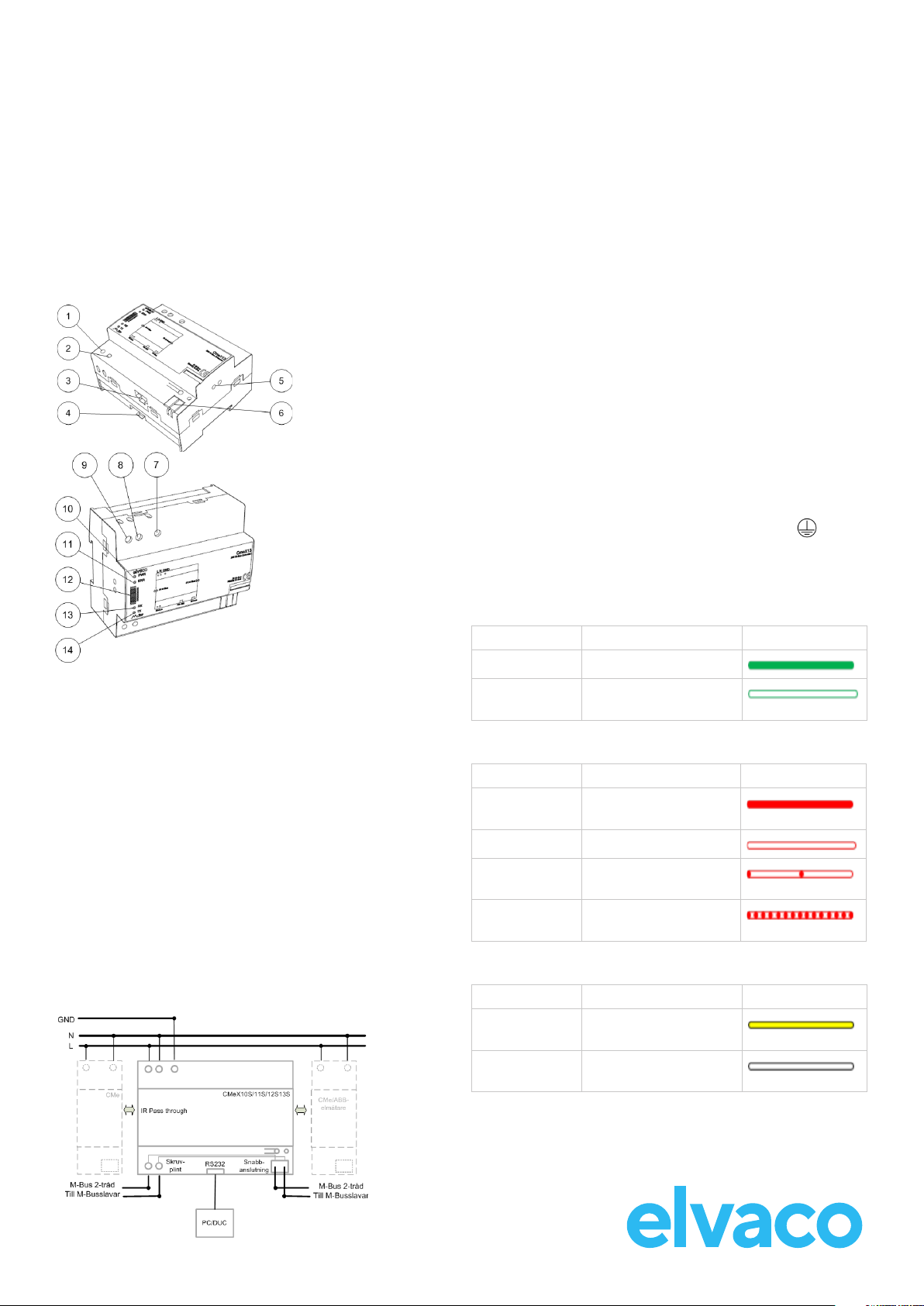
OVERVIEW
1. M-Bus out
2. M-Bus out
3. RS232 in
4. DIN-rail lock
5. IR interface
6. M-Bus out
7. Protective earth
8. Power supply N
9. Power supply L
10. Power LED (green)
11. Error LED (red)
12. Serial number
13. RX LED (yellow)
14. TX LED (yellow)
MOUNTING
The product should be mounted on a DIN-rail. The DIN-lock (4) on the
bottom is used to mount and demount the unit from the DIN-rail. To
fully comply with safety regulations, a DIN-rail enclosure must cover the
terminals and a disconnector switch on power supply must be used.
M-BUS 2-WIRE BUS
M-Bus is a multi-drop 2-wire bus with no polarity. Use a cable of area
0.25-1.5 mm2, e.g. a standard telephone cable (EKKX 2x2x0.5). Connect
the wiring to the connector (1, 2) or the push wire connector (6). Do not
exceed the maximum cable length of 5000 m.
IMPORTANT
• CMeX10S/11S/12S/13S handles from 32 up to 256 unit loads. Be
sure to use the correct model in your application. Overloading the
bus will turn on the ERR LED and turn o the M-Bus bus.
• All connected M-Bus unit loads must have unique primary or
secondary M-Bus addresses depending on addressing mode.
IR INTERFACE
The IR interface can be used beside an ABB electricity meter or
another CMeX module. Remove the IR shield (5) and mount the
CMeX10S/11S/12S/13S on the left side of the meter or CMeX module and
leave no space between the products. Do not remove the shield unless
the IR interface is used.
RS232 INTERFACE
Use the RS232 interface to use the CMeX10S/11S/12S/13S as an M-Bus
master from RS232 to M-Bus 2-wire interface.
POWER SUPPLY
The installation should be performed by a qualied electrician or an
installer with the required knowledge. If the product is mounted in an
overvoltage category 3 (OVC III) environment, an external transient
protection must be installed before the CMeX10S-13S. The power supply
should be connected via a switch so the unit can be switched o during
service work. The main supply should be connected to screw terminal
(8) and screw terminal (9). Main supply voltage should be in the range of
100-240 VAC, 50/60 Hz, fused with 10A. Connect ground
to screw terminal (7).
LED INDICATIONS
Green PWR LED
PWR LED indicates mains supply.
Mode Description Visual
Permanently on Mains power connected
Permanently o No mains power
connected
Red ERR LED
ERR LED indicates M-Bus 2-wire bus status.
Mode Description Visual
Permanently on Short circuit of the M-Bus
2-wire bus
Permanently o Normal mode, idle
Short flash every
second
No M-Bus unit loads
connected
Flashing for 1
second
M-Bus unit load collision
Yellow RX LED
RX LED indicates communication from M-Bus unit loads to DTE.
Mode Description Visual
On/Flashing M-Bus unit load is
transmitting data
O M-Bus unit load is not
transmitting data
CMeX10S-13S
DIN-mounted M-Bus master for 32-256 M-Bus unit loads

© 2022, Elvaco AB. All rights reserved. The documentation and product are provided on an “as is” basis only and may contain deciencies or in-
adequacies. Elvaco AB takes no responsibility for damages, liabilities or other losses by using this product. No part of the contents of this manual
may be transmitted or reproduced in any form by any means without the written permission of Elvaco AB. Printed in Sweden.
CMeX10S-13S Quick manual A4 English
Document id: 1090031
Version: 5.1
M-Bus
M-Bus standard EN 13757
M-Bus baud rate 300, 2400 Bit/s
Maximum connected M-Bus
unit loads
(1T=1.5mA)
CMeX10S: 32T (48mA)
CMeX11S: 64T (96mA)
CMeX12S: 128T (192mA)
CMeX13S: 256T (384mA)
Maximum cable length 5000 m
Maximum load capacitance 1.5 uF
Nominal voltage 42 VDC
IR interface Yes
Pass through Yes. Maximum of 4 CMeX Series products side
by side
Compatibility All M-Bus meters, all ABB meters with IR
interface, CMeX Series products
Approvals
EMC EN 61000-6-2, EN 61000-6-3, FCC 47 CFR
Safety EN 62368-1 2018, UL 62368-1:2014 Ed.2],
CSA C22.2#62368-1:2014 Ed.2]
TECHNICAL SPECIFICATIONS
Yellow TX LED
TX LED indicates communication from DTE to M-Bus unit loads.
Mode Description Visual
On/Flashing DTE is transmitting data
O DTE is not transmitting
data
TROUBLESHOOTING
Make sure that the product is switched o before the covers to the
screw terminals are demounted.
All LEDs are permanently off
There is a problem with the supply voltage. Please verify 100-240 VAC. If
the problem persists, the product may be malfunctioning.
Red LED is permanently on
This indicates an error on the M-Bus 2-wire bus. Please verify no short-
circuit of the bus. The voltage of the bus should be between 21-42 VDC.
Cannot read connected M-Bus unit loads
Please verify M-Bus status:
• Voltage over M-Bus unit load devices should be between 21-42
VDC.
• All M-Bus unitl load devices must have unique secondary or
primary M-Bus addresses depending on addressing mode.
• M-Bus unit load device baud rates.
TX LED is permanently on
When CMeX10S/11S/12S/13S is stacked with other CMeX Series
modules and there is a short circuit on a product which is mounted on
the left side of the issued product, the TX LED may be permanently on.
Verify left side mounted products for no short circuit.
SIMPLIFIED DECLARATION OF CONFORMITY
Hereby, Elvaco declares that the products are in compliance with the
following directives:
EU:
- 2014/30/EU (EMC)
- 2014/35/EU (LVD)
- 2011/65/EU + 2015/863 (RoHS)
UK:
- 2016 No. 1091
- 2016 No. 1101
- 2012 No. 3032
North America:
- FCC 47 CFR Part 15 Subpart B
- ICES-001 Issue 4
- CB certicate No. SE-103859
- ETL No:5017602
The complete Declaration of Conformity can be found at www.elvaco.
se/en > Search on product.
SAFETY
The warranty does not cover damage to the product caused by usage in
any other way than described in this manual. Elvaco AB can not be liable
for personal injury or property damage caused by usage in any other way
than described in this manual.
CONTACT
Technical support
E-mail: support @elvaco.com
Online: www.elvaco.com
Mechanics
Protection class IP20
Dimensions 90x65x108 mm
Weight 220 g
Connection M-Bus Pin terminal solid wire 0.6-0.8 Ø mm and screw
terminal cable 0.25-2.5 mm², 0.5 Nm tightening
torque
Mounting DIN mounted
Power supply Screw terminal cable 0.75-2.5 mm², 0.5 Nm
tightening torque
Electrical
Nominal voltage 100-240 VAC
Voltage range -10 % to +10 % of nominal voltage
Frequency 50/60 Hz
Power consumption (max) 25 W
Power consumption (nom) 0.07 W x M-Bus unit loads + 1.5 W
Overvoltage category CAT 2
Environmental
Operating temperature range -30 °C to +55 °C
Storage temperature range -40 °C to +85 °C
Pollution Degree 2
Operating altitude 0-2000 m
This manual suits for next models
3
Other Elvaco Extender manuals


