Satel CA-64 DR User manual

®
EXPANDER FOR
"DALLAS" CHIP READERS
CA-64 DR
ca64dr_en 07/08
The CA-64 DR expander for DALLAS chip readers is a device designed to interact with the
CA-64 and INTEGRA alarm control panels. It supports the DALLAS chip readers which
transfer data in the Touch Memory (DALLAS) standard. The expander can work
simultaneously with two heads of this type. Its function is to control the access to and operate
the electromagnetic door lock (or to control the operation of another device requiring the
access control). This manual is drawn up for the expander with firmware version 1.06 or later.
Note: Using of all available in the module functions is possible only in case of interact with
control panels of INTEGRA.
1. Module description
Figure 1. Diagrammatic view of the module electronics board.
Legend:
1 – LED indicator of the process of communication between control panel and expander:
−blinking – data exchange with the panel;
−ON – no data exchange with the panel (the module and the control panel connecting
wire is damaged, identification of module is not carried out or the STARTER program
is started in the control panel).
2 – package of DIP switches designed for setting individual address of the module (see:
DIP SWITCHES).
3 – LED indicator of the relay ON state.
4 – relay. The C, NC and NO of the relay are galvanically isolated from electric circuits of
the module. In normal state the C terminal is shorted to the NC terminal, while the NO

SATEL CA-64 DR
2
terminal is isolated. On actuation of the relay, the C terminal becomes shorted to the
NO terminal, and the NC terminal becomes cut off (which is signaled by the LED going
on).
Description of terminals:
+12V – power supply input
CLK, DTA – expander bus
COM – common ground
TMP – module tamper detection input (NC) – if not used, it should be shorted to
ground.
C, NC, NO – relay terminals
SIGA – data input, head A
SIGB – data input, head B
BPA – sound signaling control, head A – for the acoustic signaling to work it is
necessary to connect the sounder (buzzer) to the terminal
BPB – sound signaling control, head B – for the acoustic signaling to work, it is
necessary to connect the sounder (buzzer) to the terminal
LD1A – LED green color control, head A
LD1B – LED green color control, head B
LD2A – LED red color control, head A
LD2B – LED red color control, head B
+GA – not used
+GB – not used
DISA – not used
DISB – not used
ON – relay control input (NC) – if not used, it should be shorted to ground.
DRZWI – door status control input (NC) – if not used, it should be shorted to ground.
The RESET pins are used in the manufacturing process and should not be shorted.
1.1 DIP switches
By using the DIP switches you can set an individual address of device. The address should
be set with the switches from 1 to 5. This address must differ from those of the other modules
connected to the control panel expander bus. In order to determine the expander address,
add up the numbers set on particular DIP switches, according to Table 1.
Switch number 1 2 3 4 5
Numerical equivalent
(for switch in ON position) 1 2 4 8 16
Table 1.
The five switches allow addresses to be assigned to 32 expanders (numbers from 0 to 31).
Addresses of the expanders connected to one bus may not be repeated, while the
addressing sequence is optional. It is recommended that you assign consecutive addresses,
starting from zero, to expanders and other modules connected to one bus. This will permit
problems to be avoided during extension of the alarm system.
Position of the switches 6 and 7 is irrelevant. The switch 8 must be set in ON position.

CA-64 DR SATEL
3
Fig. 2. Example of DIP-switch settings.
Fig. 3. Example of DIP-switch settings.
2. Mounting and installation
The expansion modules can be mounted in the CA-64 OBU-EXA metal housing, or in the
OPU-1 A plastic ones.
Note: Prior to starting the module hookup, switch off power supply of the security system.
1. Fasten the expander board in its housing.
2. Using cables, connect the terminals CLK, DTA and COM to the expander bus on the
control panel main board.
3. Using the DIP switches, set up the appropriate expander address. Set the switch 8 in ON
position.
4. Connect the DALLAS head leads in according to the DALLAS chip reader manual.
5. If the acoustic signaling is to be carried out, connect the sounder (buzzer) to the BPA/BPB
and COM terminals.
6. Where the door is to be opened with a monostable switch, the leads of that button are to
be connected to the terminals ON and COM.
7. Connect the leads of the tamper contact on expander housing to the terminals TMP and
COM. Where two expanders are installed in the housing, the TMP input of one expander
is to be shorted to ground, and the contact leads are to be connected to the TMP input of
the other expander.
8. Connect leads of the door status control detector to the terminals DRZWI and COM.
9. Connect the leads for operation control of the door electromagnetic lock to the relay
terminals C, NC and NO.
10.Connect the module power supply leads to the terminals +12V and COM. The expander
supply voltage need not be provided from the control panel main board. A power supply
unit or another expander with power supply can be used for this purpose.
3. Starting the expander
1. Turn on power supply of the security system. The LED indicating communication with the
alarm control panel will come on with steady light.
address:
6
address:
22

SATEL CA-64 DR
4
2. Call the "Expander identification" function in the LCD keypad (ÆService mode ÆStructure
ÆHardware ÆIdentification). The identification completed, the LED indicating
communication with the alarm control panel will start blinking.
Note: In the process of identification, the control panel writes to the module memory
a special (16-bit) number intended to detect the module presence in the system.
Replacement of the expander with another one (even having the same address set up
on the switches) without a new identification will trigger an alarm (module tamper –
verification error).
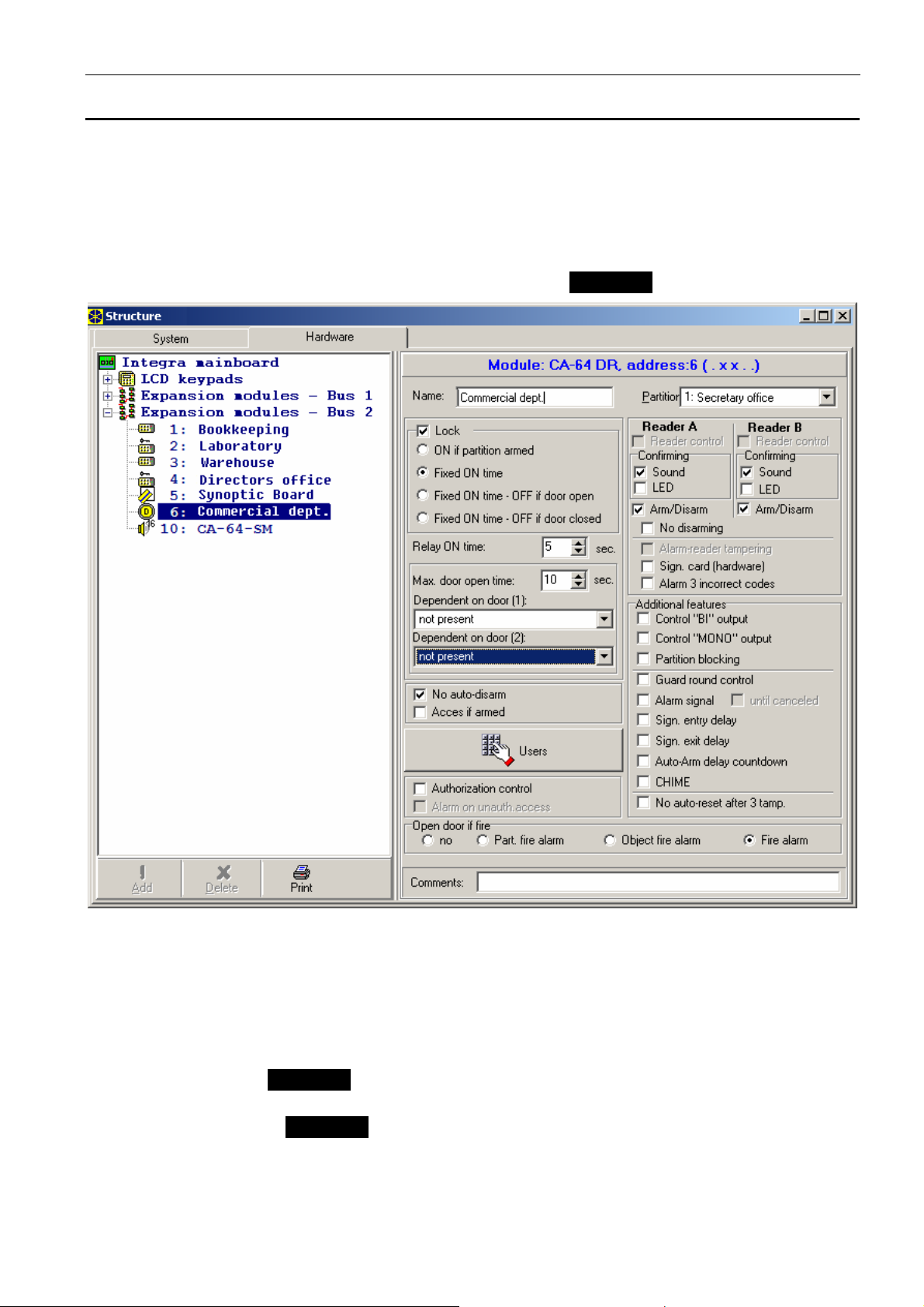
3. Using the LCD keypad or computer (DLOAD64 or DLOADX program, depending on the
control panel type), perform programming of the module functions and assign the users
authorized to use the given reader.
4. Save the module settings in the control panel memory.
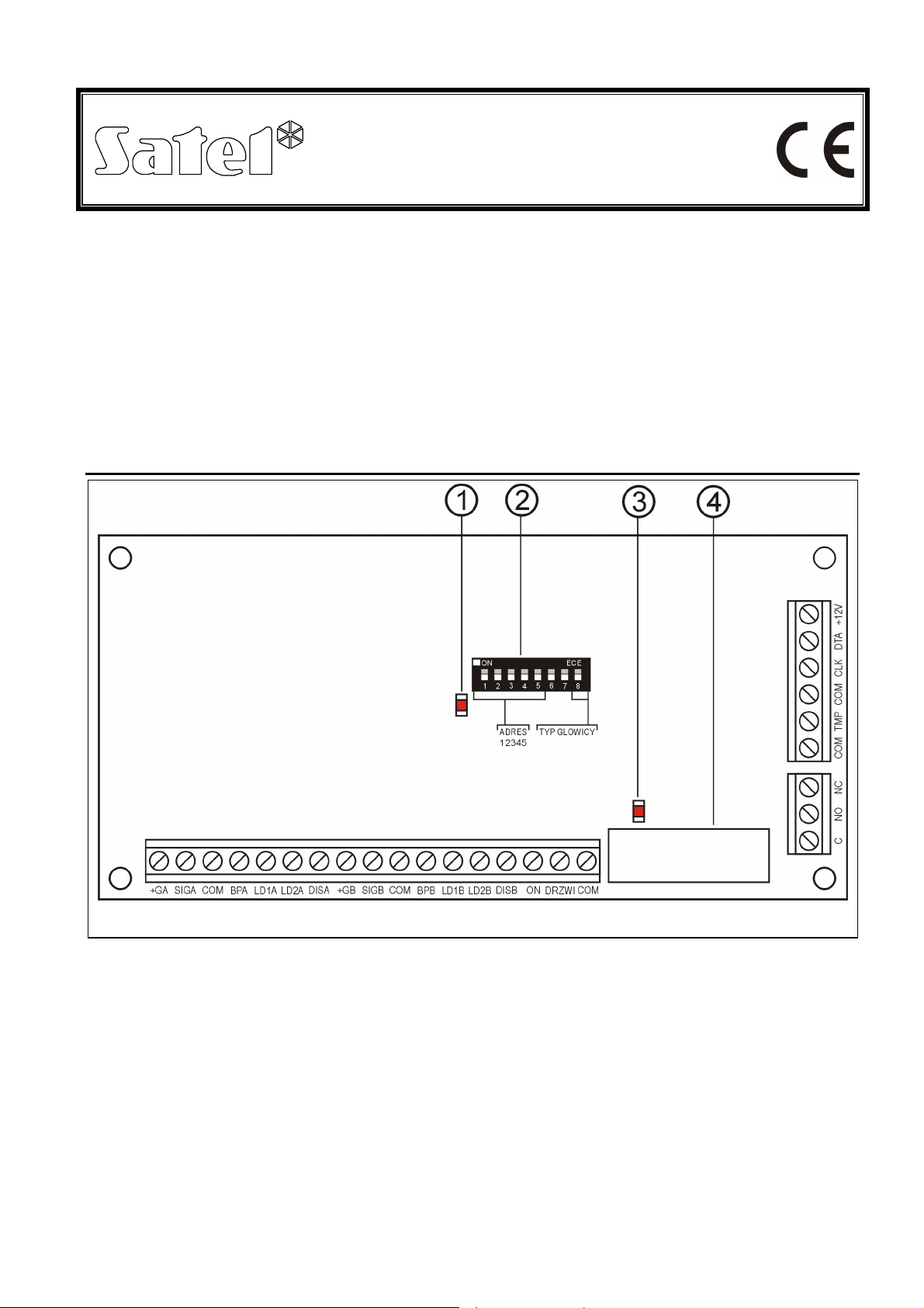
4. Description of expander operation
The expander can simultaneously interact with two heads (designated in this manual with the
letters Aand B), which read out the unique code of a DALLAS chip. To use the chip, touch
the head socket with it and press it in slightly, so as to close the expander electric input
circuit.
Touching the reader with the chip will be recognized by the expander similarly as the entry of
password from the partition keypad, confirmed by pressing the key. Holding the chip (for
about 3 seconds) will be recognized as the entry of password from the partition keypad,
confirmed by pressing the key. The way of reaction to touching the reader with the chip
or to holding the chip depends on the expander settings. By using the DALLAS chip you can:
−control the expander relay. To perform the relay control, touch the reader with the chip.
The relay can be used to control the door electromagnetic lock, latch, lighting, actuating
devices (ventilation, pumps, etc.). The mode of relay operation depends on the
programmed function.
−disarm the system and clear alarms. Disarming/alarm clearing takes place when the
reader is touched with the chip, unless the "ON if partition armed " function is selected for
the relay. If this is the case, the chip must be held longer.
−arm the partition (only INTEGRA control panels). In order to do so, activate the "Arming"
option for the selected reader and held the chip longer.
Having received the DALLAS chip code from the reader, the expander will send the code to
the alarm control panel. The panel will verify whether the user of the particular chip is
authorized to operate the expander. Information on positive or negative verification is sent to
the expander, and from there – to the reader, which can signal accordingly by means of
LEDs whether the command has been carried out or rejected (the way of signaling depends
on the control panel firmware and is described below in this document). Additionally, the
signaling can be effected by means of external LEDs or a buzzer connected to the expander.
If the verification is positive, the expander will perform the command according to its
preprogrammed settings.
The expander has the ON input to control operation of the relay independently of the
readers. The relay can be controlled by means of this input in the same way as provided for
the heads. For example, this input can be used instead of the head B to open the door when
leaving the room. In the normal state, the common ground (0V) should be connected to the
ON input. In order to activate the relay, disconnect the input from the ground. It is possible to
connect e.g. an NC type monostable switch or a remote control set to the ON input.
Performance of the relay control function through the head A will generate a "User access"
type of event, and through the head B – the "User exit" type of event in the system. Control of
the ON input will not be recorded in the memory of events.

CA-64 DR SATEL
5
5. Programming the module settings
The expander can be programmed by means of LCD keypad (ÆService mode ÆStructure
ÆHardware ÆExpanders ÆSettings Æexpander selection) or computer with a suitable
program (DLOAD64 or DLOADX). The settings and options available for programming are
described below. Abbreviations from the LCD keypad display are shown at some of the
functions in square brackets.
Note: Some options are only available when the module is working in conjunction with the
INTEGRA control panels. These are marked by the INTEGRA name.
Fig. 4. DLOADX program window with options related to expanders of DALLAS chip readers.
Name – the option to give an individual (16-character) name to the module. This option can
be accessed in the LCD keypad as follows: ÆService mode ÆStructure ÆHardware
ÆExpanders ÆNames Æexpander selection.
Partition – assignment of the module to a partition selected from the list.
Lock operation – option available in the LCD keypad – its activation provides access to the
Lock submenu. INTEGRA
Lock – option available in the DLOADX program – its activation provides access to the lock
operation options. INTEGRA
The options "Lock operation" (LCD) and "Lock" (DLOADX) refer to operating the
electromagnetic door lock (or another device that requires the access control to be
operated) by means of the reader. This function is made available to any user selected in
the "Users" option. The operation is effected by control of the relay contacts.

SATEL CA-64 DR
6
Lock feature
ON if partition armed [On if part. armed] – selecting this option sets the bistable operating
mode of the relay (i.e. the status of NO and NC relay contact changes to the opposite
one when the partition is armed and returns to the normal state when the partition is
disarmed). INTEGRA
Note: The expander relay is activated after the partition is armed by any means. Return of
the relay to its normal state will take place after reading in the chip to the head
connected to the particular expander (holding the chip – if the system is armed;
touching the reader – if the system has been disarmed).
Fixed ON time – the DALLAS chip code having been read out, the relay gets activated for
the time period entered in the "Relay ON time", and then returns to its normal state.
Fixed ON time – OFF if door open [ON, open ÆOFF] – the relay is active until the door
is opened (the DRZWI input disconnected from common ground), but not longer than
for the "relay ON time".
Fixed ON time – OFF if door closed [ON, closeÆOFF] – the relay is active during the
time when the door is open (the DRZWI input disconnected from common ground)
and deactivates on closing the door (reconnection of the DRZWI input to common
ground), but not longer than for the "relay ON time".
Relay ON time – the time period during which the relay is active. Duration of the "relay ON
time" can be from 1to 255 seconds.
Authorization control [Unauthor. event] – opening the door without using the chip will
generate an "Unauthorized door opening" event, it can also be signaled on the output
type 93 (UNAUTHORIZED DOOR OPENING).
Alarm on unauth. access – when the partition to which the module is assigned is armed,
unauthorized opening of the door will trigger the alarm and can be additionally signaled
on the output type 94 (ALARM –UNAUTHORIZED DOOR OPENING).
Max. door open time – this option defines the time after expiry of which the module will
report the "long open door" event to the control panel and activate the audible alarm.
The duration can be set from 0to 255 seconds. Setting the zero will deactivate the door
status control function.
Dependent on door 1 (or Dependent on door 2)– this function provides a list to choose the
door which must be closed for the lock to operate. Monitoring of the door state is
effected through the DRZWI input or the zone type 57 (TECHNICAL –DOOR OPEN). Two
dependent doors can be selected. The function allows to create a "sluice" type passage.
No auto-disarm [Code* n. disarm] – with this option enabled, touching the reader with the
DALLAS chip will neither disarm the partition nor activate the relay (will prevent the door
from being opened).
Acces if armed [Code* in arm] – with this option enabled, touching the reader with the
DALLAS chip will not disarm the partition, but it will activate the relay (and enable
opening of the door). The option is available when the NO AUTO DISARM [Code* n.
disarm] is enabled.
Master users/Users – this function defines master users/users authorized to use the
readers.
Readers – functions directly related to the DALLAS chip readers.
Sound confirmation [Reader A sound/Reader B sound] – after the DALLAS chip code
has been read out by the control panel, appropriate sound signals will be generated
(see SIGNALING).
LED confirmation [Reader A LED/Reader B LED] – after the DALLAS chip code has
been read out by the control panel, visual signals will be generated on the LEDs, in
much the same way to the audible signals (see SIGNALING).

CA-64 DR SATEL
7
Arming [Reader A arm./Reader B arm.] – this option defines whether the partition can be
armed by using the DALLAS chip. Hold the chip at the reader to arm the partition.
INTEGRA
Hardware signaling of readout – activation of this option will start the chip code readout
signaling which is independent of the control panel. INTEGRA
Alarm – 3 incorrect codes – with this option enabled, alarm will be generated after three
attempts to read in an invalid DALLAS chip. INTEGRA
Control BI output – reading the code of chip assigned to the "Bi output control" type of
codes will control the output type 25 (BI SWITCH) in the given partition (if the code is
authorized to access the given partition and is included in the list of module users).
Control MONO output – reading the code of chip assigned to the "Mono output control" type
of codes will control the output type 24 (MONO SWITCH) in the given partition (if the
code is authorized to access the given partition and is included in the list of module
users).
Partition blocking – reading the chip of the guard or a user having the "Temporary partition
blocking" type of code when the partition is armed will temporarily block the time of
entry in the partition the module is assigned to. The bypass duration is determined in
the partition parameters (for the guard) or in the user code parameters.
Guard control – reading the chip of the user having the "Guard" type of code will be
recorded as completion of the round.
Signaling – options related to signaling by LEDs of the reader or by the buzzer connected to
expander. INTEGRA
Alarm signaling (fixed time) – acoustic alarm signaling in the given partition (through the
total duration of alarm).
Alarm signaling (until canceled) [Alarm (latch)] – acoustic alarm signaling in the given
partition until the alarm is cleared.
Signaling entry delay – acoustic signaling of the countdown of entry delay time.
Signaling exit delay – acoustic signaling of the countdown of exit delay time.
Auto-Arm delay countdown – acoustic signaling of auto-arming delay countdown in the
group to which the module is assigned.
No auto-reset after 3 tampers – each expander will automatically disable its tamper alarm
function after three consecutive (not cleared) tamper detection alarms, which prevents
the same events from being saved repeatedly in the control panel memory. This option
allows the blocking function to be deactivated.
Open door if fire [Doors on fire] – control mode for the door blocking during fire alarm:
−no – fire alarm has no effect on the door blocking,
−Partition fire alarm – fire alarm in the partition will unblock the door controlled by the
module,
−Object fire alarm – fire alarm in the object will unblock the door controlled by the
module,
−fire alarm – fire alarm in the system will unblock the door controlled by the module.
6. Signaling
The mode of acoustic/optical signaling is conditional upon the alarm control panel program.
The expander has two outputs to control the LEDs' status and one output to control audible
signaling. The DALLAS chip readers come with a built-in two-color LED. It is also possible to
connect extra LEDs or a buzzer to the expander.

SATEL CA-64 DR
8
Meanings of the sound signals generated on reading the DALLAS chip code are as follows:
•one short beep (accompanied by a single flash of the LED) – acknowledgement of the chip
code readout – a hardware function, performed by the expander;
•two short beeps – starting the chip read-in function, acknowledgement of the first chip
read-in;
•one long beep – arming refused – there are violated zones for which the "Priority" option is
activated;
•two long beeps – chip code not recognized by the panel,
•three long beeps – chip code recognized, but the user is not authorized to get access to
the lock (relay control);
•four short and one long beeps – acceptance of the chip code and activation of the relay,
the second correct readout of the user's new chip,
•five short beeps – dependent door open (the relay has failed to activate);
•short beeps (with no duration limit) – too long open door;
•a sequence of two short beeps repeated three times – the code of the given DALLAS chip
user needs to be changed (the "Notify of necessity to change access code" is selected in
the control panel).
Additionally, in case of operating with INTEGRA control panels, the following situations can
be signaled acoustically:
•Alarm in partition – continuous beep.
•Fire alarm – one long beep every second.
•Countdown of entry delay – short beeps every 3 seconds.
•Countdown of exit delay – long beeps every 3 seconds terminated with a series of short
beeps (lasting 10 seconds) and one long beep. The mode of "exit delay" signaling
indicates that the countdown is drawing to an end before arming.
•Auto-arming delay countdown (timer-controlled partitions) – a series of 7 sounds (of
diminishing length).
Meanings of visual signaling:
•LED blinking red – no communication between module and control panel (cable
connecting module with control panel is damaged, identification of module is not carried
out yet or the STARTER program is running in the control panel;
•LED blinking red with varying frequency – exit delay countdown
•green LED light – the system is disarmed;
•red LED light – the system is armed (only in case of operating with INTEGRA control
panel);
•LED blinking alternately red and green:
−alarm (only in case of operating with INTEGRA control panel);
−waiting for the first read-in of the new chip;
−waiting for the repeated read-in of the new chip.
The installer can also activate the "LED confirmation" option. In this case, the LED color will
change from green to red after the chip readout in accordance with the above described
audible signaling.

CA-64 DR SATEL
9
7. Technical data
Supply voltage .................................................................................................. 10.5V...14V DC
Maximum current consumption (without heads) ...............................................................70mA
Maximum relay switchable voltage ..............................................................................AC 250V
Maximum relay switchable current.........................................................................................2A
Environmental class................................................................................................................. II
Operating temperature range.............................................................................-10 °C...+55 °C
Dimensions of module electronics board ................................................................ 68x140 mm
Weight.................................................................................................................................. 89g

The latest EC declarations of conformity and certificates are available for
downloading on the website www.satel.pl
SATEL sp. z o.o.
ul. Schuberta 79
80-172 Gdańsk
POLAND
tel. + 48 58 320 94 00
info@satel.pl
www.satel.pl
Table of contents
Other Satel Extender manuals

Satel
Satel INT-IORS User manual

Satel
Satel ACX-220 User manual

Satel
Satel INT-PP User manual

Satel
Satel CA-64 O-OC User manual

Satel
Satel CA-64 SR User manual

Satel
Satel CA-64 PP User manual

Satel
Satel INT-R User manual

Satel
Satel ACX-200 User manual

Satel
Satel INT-IORS User manual

Satel
Satel ACX-201 User manual

Satel
Satel CA-64 ADR User manual

Satel
Satel CA-64 OPS-OC User manual

Satel
Satel ACX-201 User manual

Satel
Satel ACX-210 User manual

Satel
Satel CA-64 EPS User manual

Satel
Satel ACX-210 User manual

Satel
Satel INT-E User manual

Satel
Satel INT-R User manual

Satel
Satel CA-64 PP User manual

Satel
Satel CA-64 EPS User manual