Elvid VSW-4H-USB User manual

USER
MANUAL
VSW-4H-USB
4-Input HDMI Switcher with USB Output

2
The Elvid VSW-4H-USB Broadcast Video Switcher is a powerful yet compact unit that puts advanced switching and professional video effects
at your ngertips. Great for livestreaming and broadcast applications, this switcher will boost the production value of any multicamera
presentation, concert, panel discussion, or interview.
The VSW-4H-USB features four HDMI inputs that support up to full HD 1080p video, and a USB input to upload your graphics, logos, and
artwork to the switcher’s media library. Two congurable mic/stereo line inputs can add live narration or music to the production. Perform
creative transitions, mix audio, and use the pattern generator and extensive pattern library to set up downstream and upstream keyers, all
from the intuitive control panel. Flexible output options let you place a multiview screen in your control room or at your workstation, and a
second monitor that displays the live broadcast or any one of the incoming video sources. The switcher’s built-in encoder automatically scales
and deinterlaces incoming video signals and outputs video to user-selected resolutions up to 1080p. The live broadcast can be outputted to a
broadcast device, projector, or recorder, and simultaneously streamed to the internet via the USB output.
THANK YOU FOR CHOOSING ELVID.

3
Precautions ..................................................................................................................................................................................................................................................................4
Overview .......................................................................................................................................................................................................................................................................5
Powering the Switcher ............................................................................................................................................................................................................................................6
Connecting the Inputs..............................................................................................................................................................................................................................................7
Connecting the Outputs ......................................................................................................................................................................................................................................... 8
Checking Your Video Inputs ...................................................................................................................................................................................................................................9
Conguring the Outputs .......................................................................................................................................................................................................................................10
User Interface ............................................................................................................................................................................................................................................................11
Switching ....................................................................................................................................................................................................................................................................13
PIP and POP ..............................................................................................................................................................................................................................................................15
Screen Patterns ........................................................................................................................................................................................................................................................16
Freezing a Picture ....................................................................................................................................................................................................................................................17
Using the Upstream Keyer ...................................................................................................................................................................................................................................18
Using the Downstream Keyer ............................................................................................................................................................................................................................20
Working with Audio................................................................................................................................................................................................................................................21
System ........................................................................................................................................................................................................................................................................23
Connecting to a Network .....................................................................................................................................................................................................................................24
Tally .............................................................................................................................................................................................................................................................................25
Firmware Updates ..................................................................................................................................................................................................................................................26
Menus .........................................................................................................................................................................................................................................................................27
Specications ...........................................................................................................................................................................................................................................................32

4
• Please read and follow these instructions, and keep this manual in a safe place.
• Keep this product away from water and any ammable gases or liquids.
• Do not expose this product to humidity or extreme heat or cold.
• Make sure this product is powered off when plugging it into a power source.
• Use only the correct, recommended voltage.
• Do not attempt to disassemble or repair this product—doing so will void the warranty, and Elvid will not be responsible for any damage.
• Handle this product with care. Avoid any impacts to this product.
• Do not block the vents in this product.
• Disconnect this product from its power source before storage and during electrical storms.
• Do not use chemical solutions to clean this product. Clean it with only a soft, dry cloth.
• Make sure that this product is intact and that there are no missing parts.
• All images are for illustrative purposes only.
PRECAUTIONS
5
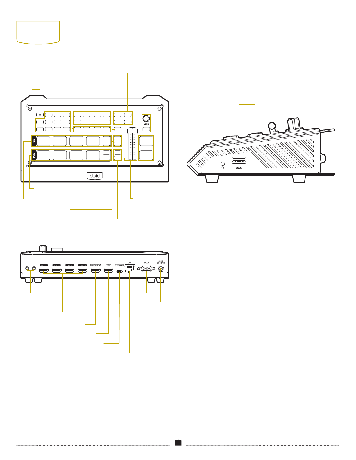
OVERVIEW
CONTENTS INCLUDE
• Power supply (12 V, 2 A)
• USB cable (USB Standard-A to Type-C)
• Tally connector (DE-15)
LINE 1 LINE 2
VSW-4H-USB
MASTER
MIC 1 MIC 2
CHROMA
ON AIR ON AIR MIX
WIPE
PIP1
HDMI 2HDMI 1 HDMI 3 HDMI 4 LUMA
ON AIR ON AIR DIP
INV
EXIT
CUT
AUTO
PIP2
AFV
1 2 3 4
AUDIO ON
VOL+ VOL- DSK
ON AIR ON AIR
SPEED1
SPEED2
MUTE
FTB
PATTERN
STILL
1 2 3 4
PATTERN
STILL
PATTERN
STILL
MV
LOGO
Mic/Line input
1 and 2
HDMI inputs 1–4
Multiview output
Program (PGM) output
USB Type-C™ port (output)
LAN port
Tally port
Power input
USB Standard-A port (input)
3.5 mm headphone output
Power
Program (PGM) selectors (1–4)
Preview (PVW) selectors (1–4)
Audio controls
Downstream key (DSK)
selectors
Chroma/Luma
key selectors
Multiview
selector
Transition
effects
Menu
controls
Cut/Auto selectors
T-Bar
Mute/Fade to Black controls
Speed selectors

6
POWERING
THE
SWITCHER
1. Make source and output device connections.
2. Plug the power cord into the switcher and tighten the locking ring
until secure. Plug the power adapter into an outlet.
3. Press the Power button to turn on the switcher.
To turn off:
1. Press and hold the Power button for 3 seconds.
2. Turn the Menu knob to select YES in the onscreen prompt, then
press the knob to select. The switcher will power down after 3
seconds.

7
CONNECTING
THE INPUTS
VIDEO SOURCES
Plug HDMI cameras and other HDMI sources into the switcher’s
HDMI inputs 1–4.
Each of the HDMI windows will display the video signals when
viewing in the Multiview screen.
COMPUTER CONNECTIONS
Computers can be connected to the switcher via an HDMI cable or
with an appropriate adapter.
Note: When connecting a computer to one of the HDMI inputs, you
may need to set the computer display setting to mirror the primary
screen.
AUDIO CONNECTIONS
Connect microphones, an audio player, smartphone, or a wireless
receiver to the switcher’s audio inputs with a 3.5 mm TRS audio
cable.
The audio input accepts stereo unbalanced microphone and line-level
signals. To set the inputs to receive a mic- or line-level signal, see
Working with Audio
below.

8
CONNECTING
THE OUTPUTS
The switcher has a USB and two HDMI outputs. The HDMI outputs
can be connected to monitors, a projector, or broadcast device.
The USB output lets your computer simultaneously monitor the
Multiview, Program (PGM), or a user-selected signal, and stream it to
the internet.
Both HDMI and USB ports can be congured to output HDMI 1–4,
PGM, Clean PGM, Preview (PVW), Color Bar, or Multiview screens.
MULTIVIEW OUTPUT
The Multiview output displays seven windows onscreen: HDMI 1–4,
Preview (PVW), Program (PGM), and Status/Menu.
Use the MV button to force the Multiview output to display the
default Multiview layout.
PROGRAM (PGM) OUTPUT
The PGM output displays the nal output that’s sent to the recorder
or broadcast device. This signal is what your audience will see.
USB OUTPUT
Use the included USB cable to connect the switcher to a computer.
The computer can be used as a monitor or to stream video to the
internet.

9
CHECKING
YOUR VIDEO
INPUTS
Make sure the switcher is receiving all connected video signals.
In Program view, press the PGM buttons to check your video's
connections.
In Multiview, press the PVW buttons to check your video
connections.

10
CONFIGURING
THE OUTPUTS
The Output menu congures the switcher’s three output ports.
The Multiview port is preset to display the Multiview screen. The
Program and USB ports are preset to display the Program screen.
Each port can output any one of the HDMI 1–4, Program (PGM),
Clean Program (Clean PGM), Preview (PVW), Color Bar , and
Multiview signals.
To congure the outputs:
1. Press the Menu knob to open the menu in the status window.
2. Scroll down to Output and press the Menu knob to open the
submenu.
3. In the Interfaces submenu, choose the output signal for each port
by scrolling and then pressing the Menu knob to select it.
4. Press the Exit button to return to the main menu. Press the Exit
button again to return to the status window.
THE MULTIVIEW BUTTON
The Multiview port can be congured to display the HDMI 1–4,
Program (PGM), Clean Program (Clean PGM), Preview (PVW) signals,
or a color bar.
For example, the monitor connected to the Multiview port can
display the Clean PGM without overlays, while the monitor
connected to the PGM port will display the on-air program with
upstream and downstream effects.
The MV button toggles the Multiview screen display. If an alternate
signal is congured to be output from the Multiview port, pressing
the MV button will quickly toggle the Multiview output to display the
Multiview screen. While the Multiview screen is toggled on, the MV
button will remain backlit.
This function is useful for quickly checking the switcher's status or
accessing the menu.
Pressing the MV button again will toggle the congured output
signal.

11
USER
INTERFACE
MENU NAVIGATION
Menus are accessible only in the status window of the Multiview
screen.
PGM: The Program window displays the on-air signal that’s being
recorded and/or broadcast. Set the Program signal by selecting one
of the HDMI 1–4 PGM buttons.
PVW: The Preview window appears only in Multiview mode. Use the
preview window to prepare an input to be switched to the program
output. Set the Preview signal by selecting one of the HDMI 1–4
PVW buttons.
HDMI 1–4: The HDMI windows display the signals that are received
by all connected sources. When there’s no source, the HDMI window
is black. A green tally border appears around the window that’s
switched to preview output. A red tally border appears around the
window that’s switched to the program output.
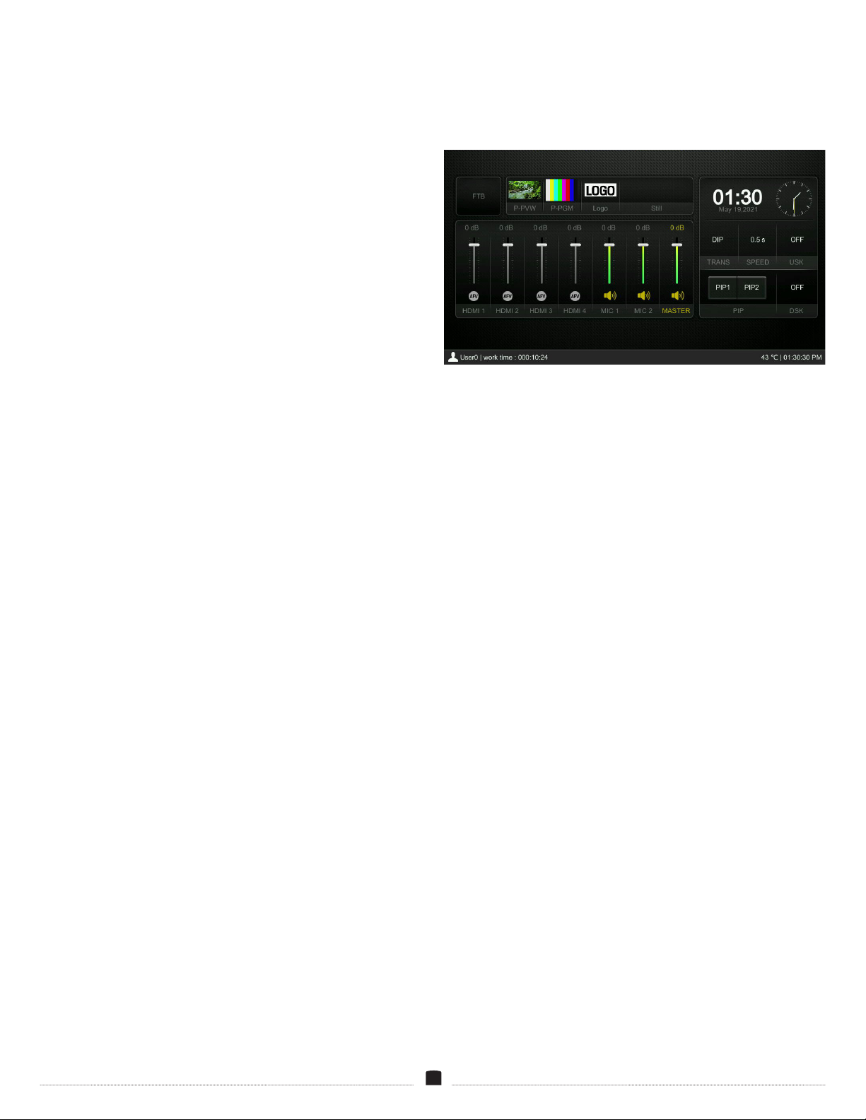
Status Window: The status window displays the audio mixer where
you can adjust the audio settings for the six audio input signals and
the master volume.
The status window also displays the date and time, pattern selection
for the PGM and PVW screens, the selected logo and still images,
and the transition selections. The active status of PIP1, PIP2,
upstream key, downstream key, and Fade to Black are also displayed.
Input Information: The HDMI 1–4 windows include overlays that
display resolution and frame rate information for each input video
signal. See
Menus/Multiview
below to turn the overlays on or off.
Note: The layout and the displayed information on each screen can
be customized to your production’s needs. For complete information
on editing and customizing these features, see
Menus/Multiview
below.
• Press the Menu knob. The menu display will open in the status
window.
• Turn the Menu knob to scroll through the main menus. Press the
Menu knob to select a menu and open its submenu.
• Scroll to a submenu item and press the Menu knob to select it. Turn
the Menu knob to change the value of the option, and press the
knob to accept the change and return to the submenu.
Press the Exit button to return to the previous menu. Press the Exit
button repeatedly to return to the status screen.
MULTIVIEW SCREEN
Connect the Multiview HDMI output to a monitor to display the
Multiview screen.
12
USING THE AUDIO MIXER
The audio mixer displays seven channels that can be individually
congured and adjusted. The switcher’s control panel features seven
buttons that correspond to each audio channel.
Press the corresponding button on the control panel, and it will blink
when the channel is activated.
When the channel is active, adjust the output volume by turning the
Menu knob.
The volume can also be adjusted with the VOL+ or VOL- buttons,
which raise or lower the volume in 3 dB increments.
Audio On: Press to turn on the audio to the selected HDMI or audio
channel, and a speaker icon will appear at the base of the fader.
Press the Audio on button again to turn the channel off. When Audio
On is set, the audio will always be on, even if the source video is
not routed to the Program output. For more on audio settings, see
Working with Audi
o below.
Note: Mic 1 and 2 inputs need to be congured to receive mic- or line-
level signals. See
Working with Audio
below.
AFV: Audio Follow Video (AFV) is available for the four HDMI
channels. When set to AFV, the audio will automatically turn on
when that video signal is routed to PGM. With AFV activated on
multiple HDMI channels, the audio will switch or fade as you switch
or wipe to a different channel.
For full details of all user-denable settings in the Multiview window
settings, see
Menus/Multiview
below.

13
SWITCHING
The VSW-4H-USB offers four transition options: cut, wipe, mix, and
DIP. Cut instantly transitions from PVW to PGM. Transitions like
wipe, mix, and DIP appear as an effect and can be congured to your
needs and production style.
CUT
1. Select the video signals with the PGM and PVW buttons. The
selected PGM button will glow red. The selected PVW button will
glow green.
2. Press the CUT button. The Preview signal will cut to the Program
window. The signal that was in the Program window will now
appear in the Preview window.
3. Press the CUT button again to cut back to the rst signal.
In the HDMI 1–4 windows, the PGM video is highlighted with a red
border. The PVW video has a green tally border.
WIPE
Transitions from the Preview signal to the Program signal with a
preselected pattern and speed.
To use the wipe effect, rst select the Wipe button on the control
panel.
Using the AUTO Button
1. Select the video signals with the PGM and PVW buttons. The
PGM button that is on-air will be red. The selected PVW button
will be green.
2. Select the Speed 1 or Speed 2 button.
To adjust the transition speed of the Speed 1 and Speed 2 buttons,
see
Transition Speed
below.
3. Press the AUTO button. The Preview signal will transition to the
Program window with the selected wipe transition at the selected
speed. The signal that was in the Program window will now
appear in the Preview window.
4. Press the AUTO button again to transition back to the rst HDMI
signal using the same wipe effect.
Using the T-Bar
1. Select the video signals with the PGM and PVW buttons. The
PGM button that’s on-air will glow red. The selected PVW button
will glow green.
2. Slide the T-Bar all the way to the top or bottom. The transition will
proceed at the speed you move it.
3. The transition is not complete until the T-Bar is completely up or
down. When the T-Bar reaches the top or bottom, the status of
both HDMI signals will reverse in the HDMI windows and HDMI
buttons.
Selecting a Transition Pattern
The switcher has 11 preset transition patterns.
Select a pattern from the Transitions menu (see
Menus/Transitions
below). The selected pattern will play when you press the AUTO
button or use the T-Bar.
Transition Speed
The amount of time a transition takes when the AUTO button is
pressed.
To set the transition speed, select the Speed 1 or Speed 2 button
before you press the AUTO button. The selected Speed button will
glow.
Speed 1 is preset to 0.5 seconds, and Speed 2 is preset to 1.5
seconds. The transition speed can be set in the Transitions menu (see
Menus/Transitions
below).
MIX
The Mix transition effect cross dissolves the Preview and Program
signals. As one fades out, the other fades in. This transition can be
controlled with the AUTO button or the T-Bar.
To use the mix effect, rst select the Mix button on the control panel.
1. Select the video signals with the PGM and PVW buttons. The
selected PGM button will glow red. The selected PVW button will
glow green.
2. Select the Speed 1 or Speed 2 button.
3. Press the AUTO button. The Preview signal will transition to the
Program window. The signal that was in the Program window will
now appear in the Preview window.
4. Press the AUTO button again to transition back to the rst HDMI
signal using the same mix effect.

14
DIP
Dip to Color transition (DIP) fades the Program signal to black and
then fades up the Preview signal.
To use the DIP transition effect, rst select the DIP button on the
control panel.
1. Select the video signals with the PGM and PVW buttons. The
selected PGM button will glow red. The selected PVW button will
glow green.
2. Select the Speed 1 or Speed 2 button.
3. Press the AUTO button. The Preview signal will transition to the
Program window. The signal that was in the Program window will
now appear in the Preview window.
4. Press the AUTO button again to transition back to the rst HDMI
signal using the same dip effect.
Note: To set the screen color the DIP effect fades to, see the
Menus/
Transitions
section below.
FADE TO BLACK AND MUTE
The FTB button quickly fades the live on-air signal to black and
mutes the audio. This feature is good for emergencies or to end a
broadcast.
Pressing the FTB button again will restore video and audio.
The Mute button mutes the master volume without affecting the
video. Press again to restore the audio at its previous volume.
15
PIP AND POP
The PIP and POP features place two separate windows onscreen,
each with its own separate video source.
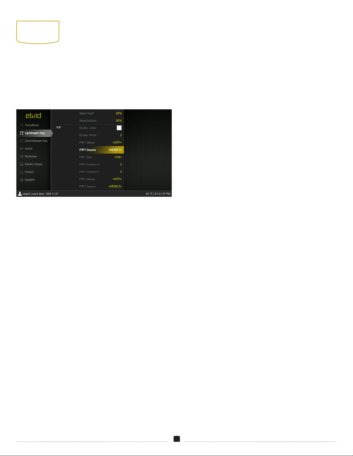
PICTURE IN PICTURE (PIP)
1. Open the Upstream Key menu and scroll to PIP.
2. Select PIP1 Source and PIP2 Source menus to set the video source
or image that will appear in each window.
Note: Other aspects of the PIP windows like window size, window
position, and border color and width can be congured in this
menu. See Menus/Transition below.
3. Press the PIP1 and/or PIP2 buttons on the control panel, and the
two PIP windows will appear at the top left and right sides of the
PVW screen.
4. Press the ON AIR buttons to add or remove the PIP windows to or
from the PGM screen.
When PIP is activated, it’s preset to appear only in the Preview
window. Use the PIP1 Status and PIP2 Status menus to set whether
the PIP windows appear in the Program window or in both Program
and Preview windows when you press the ON AIR buttons. See
Menus/Transitions
below.
PICTURE ON PICTURE (POP)
POP places two windows over the background screen, each spanning
50% of the screen’s width and height at the center of the screen.
When POP is enabled in the Upstream Key menu, it automatically
overrides PIP.
If the POP windows are congured to appear on the Preview screen,
press the PIP1 or PIP2 ON AIR buttons to add them to the Program
window.
To congure PIP and POP, see
Menus/Upstream Key
below.

16
SCREEN
PATTERNS
The switcher generates patterns that are displayed in the Program
and Preview windows when no source signal is selected or when the
PATTERN button is enabled. Select between Black, Color Bar, Color 1,
Color 2, and Image. The PGM pattern is preset to Color Bar, and the
PVW pattern is preset to Image.
SWITCHING TO A PATTERN
Pressing the Pattern button interrupts the video and audio signal
and replaces it with a generated pattern.
To resume the video and audio signal, select an HDMI source with
the PGM and PVW buttons.
SETTING PATTERNS
The Pattern menu selects what images will be displayed when the
PATTERN button is enabled. To select the onscreen pattern from the
Media Library, follow these steps:
In the Multiview screen, press the Menu knob to open the menus.
Scroll down, and select the Media Library.
PATTERNS
Select between Black, Color Bar, Color 1, Color 2, and Image.
Black / Color Bar
Select Black to display a black screen. Select Color Bar to display the
preset color bar.
Image
Default Image: Choose from 39 preloaded images in the library. Use
the Menu knob to scroll to the desired pattern, and press the Menu
knob to select it.
Local Image: Uploads and saves images from a USB ash drive, and
displays saved images in the local image library.
To select local images, insert a ash drive into the switcher’s USB
port, and scroll to Local Image in the Pattern menu. The images on
the ash drive will be displayed.
Use the Menu knob to scroll to the desired images, and press the
Menu knob to select images as the default patterns on the PGM and
PVW screens, or delete them from the library.
Capture Image: Captures screenshots from PGM, Clean PGM, or
HDMI 1–4 screens. This menu displays the image library for image
selection or deletion.
Use the Menu knob to scroll to and select or delete the image that
will appear when the PATTERN button is activated.
Select a blank frame and select a source. The switcher will capture
whatever is onscreen when the selection is made.
Color 1/Color 2
Hue: Select a hue from 0° to 360° on the displayed color wheel. Use
the Menu knob to adjust the hue in 1° increments.
Saturation:Adjust the saturation level of the selected hue from 0%
and 100%.
Luminance: Adjust the luminance level of the selected hue from 0%
(black) to 100% (white).

17
FREEZING A
PICTURE
Press the Still button to freeze the picture in the PGM or PVW
screens. Press the STILL button again to return to the video signal.
Still images can be captured and stored in the Media Library. See
Patterns
above.

18
USING THE
UPSTREAM
KEYER
The upstream keyer lets you layer video, titles, graphics, and
animation over a live video or graphic background with the Luma and
Chroma Keys. Any key applied to the preview window will transition
to the program window.
Luma Key and Chroma Key effects are congured in the Upstream
Key menu.
LUMA KEY
Select Luma Key when the video or graphic you want to show
onscreen is brighter than the background. Luma keys work best with
high-contrast images like white elements on a black background, so
you can use the contrast to cut out the black background and replace
it with live video or broadcast graphics.
Luma Status Menu
The Luma Status menu sets the output of the luma effect.
OFF: The luma key effect is not visible.
KEY (PVW): Displays the luma key effect on only the Preview
window.
ON AIR (PGM): Displays the luma key effect on only the Program
window.
KEY & ON AIR: Displays the luma key effect on both windows.
To quickly change the output status, use the LUMA and ON AIR
buttons on the control panel.
Key Source: This is the primary layer on which you will add the ll.
The ll will show in the transparent areas of the key. You can select
an image, a live video from HDMI 1–4, or a color.
Fill Source: This is the layer that will show in all the transparent
areas of the key.
To create a luma key effect, follow these steps:
1. Open the Upstream Key menu and scroll to the Luma Key section.
2. In the Key Source menu, select a pattern from the menu.
Important! If an image is selected for the key source, it must be
selected in the Media Library. (See
Screen Patterns
above.)
3. In the Fill Source menu, select an image, video, or color from the
menu.
4. Insert the background by selecting a video source from the
program selectors. The full Luma Key effect will appear on the
Preview window.
5. Add the effect to the live broadcast. Press the On Air button to
instantly add it to the Program window. Or use a transition effect
to add it to the Program window.
6. To turn the effect off, press the LUMA button on the control panel.
See the
Upstream Key
menu for a description of all the congurable
Luma Key features.
Clip and Gain
Clip: Clip adjusts the Key source’s transparency threshold. Raise the
key clip percentage to increase the level at which the key becomes
transparent. Lower the percentage to decrease the transparency level
and reveal more of the background. If the screen is black, the clip is
too low. If the key is not visible, the clip is too high.
Gain: In Luma Key, gain adjusts the transition between transparent
and opaque areas of the key. Raise the gain to see partial
transparencies. Lower the level to see only opaque and transparent
areas without any partial transparency. In Chroma Key, gain adjusts
the transparency of areas that are similar to the key color. Apply
more Key Gain if the light areas become too transparent.
Using the Same Key and Fill Source
The Luma Key can be used to add a graphic, logo, or image to
a background. This differs from the downstream keyer (see
Downstream Keyer
below) because it can be transitioned onto a
background with the AUTO or CUT buttons, or the T-bar.
1. In the Key Source menu, select a graphic or image.
2. In the Fill Source menu, select the same image or graphic.
3. Use the ON AIR button to instantly add it to the Program window,
or use the AUTO or CUT buttons or the T-bar to transition the
effect to the Program window.
Invert Key
Selecting the Invert Key menu option turns it on. When turned on, it
inverts the key and ll sources.

19
CHROMA KEY
Chroma key creates a key with a specic color. Any area with that
color will be transparent. Chroma key is effective when shooting
talent in front of a green or blue screen. The chroma key removes the
specied color, and whatever image or graphic is on the background
behind it will be visible.
To create a chroma key effect, follow these steps:
1. Open the Upstream Key menu, and scroll to the Chroma Key
section.
2. In the Key Source menu, select a chroma key source from the
menu options.
Important! If Image is selected for the key source, it must be
selected in the Media Library. See
Screen Patterns
above.
3. The switcher’s chroma key is preset to green. The selected color
is displayed in the Fetch Color menu. To select another color, use
the Fetch Color control, or set the color manually using the RGB
menus.
RGB: Each color menu spans from 0 (no color) to 255 (full color).
For example, full green is R=0, G=255, B=0. If you know the
color’s RBG setting, use the RGB menu to manually set it.
Fetch Color: The Fetch Color control lets you select a color from
the onscreen image of your key source.
In the submenu, select Refresh Image to capture the screen
image. A small square cursor will appear onscreen. Use the Fetch
X and Fetch Y menus to move the cursor to a spot where the
desired color appears. Press the Menu knob to accept the X and
Y cursor positions. The color and corresponding RGB setting will
appear at the bottom of the menu.
4. Insert the background by selecting a video source from the
preview selectors. The full chroma key effect will appear in the
Preview window.
5. Add the effect to the live broadcast. Press the On Air button to
instantly add it to the Program window. Or use a transition effect
to add it to the Program window.
6. To turn the effect off, press the CHROMA button on the control
panel.
See
Upstream Key
for a description of all the congurable chroma
key features.
Chroma Status Menu
The Chroma Status menu sets the output of the chroma effect.
OFF: The chroma key effect is not visible.
KEY (PVW): Displays the chroma effect only in the Preview window.
ON AIR (PGM): Displays the chroma effect only in the Program
window.
KEY & ON AIR: Displays the chroma effect in both windows.
To quickly change the output status, use the CHROMA and ON AIR
buttons on the control panel.
Invert
Selecting the Invert Key menu option turns it on. When turned on, it
swaps the key and ll sources.
MASK (LUMA & CHROMA KEY)
Luma and Chroma Key menus feature mask adjustment menus.
When the Mask Enable menu is on, an adjustable rectangle can be
congured to crop out any portions of the luma/chroma key effect
you want to hide.
For example, if talent is talking in front of a green screen, but you
want to cut out a microphone that’s in the picture frame, resize the
mask until the microphone is no longer visible.
1. Select the Mask Enable menu to turn the mask feature on.
2. Use the Menu knob to adjust the top, bottom, and sides of the
luma or chroma key. Use the Menu knob to change the values,
and press the Menu knob to accept the setting.
3. Select the Mask Enable menu again to turn it off.

20
USING THE
DOWNSTREAM
KEYER
The downstream key overlays all video that’s switched to the
Program window. Graphics that are added with the downstream
key remain on the Program window regardless of transitions. This is
useful for logos, lower thirds, and other graphics that need to remain
onscreen throughout the program.
To create a downstream key effect, follow these steps:
1. Open the Downstream Key menu.
2. Select a Key Source from the menu options. The key source is the
graphic that appears onscreen.
3. Select a ll source from the from the menu options.
• Selecting the same image as the key and ll source will place a
static graphic onscreen.
• Selecting a separate ll source allows you to augment the key
source with a background color, pattern, or video.
Important! If an image is selected for the key or ll source, it must be
selected in the Media Library. See
Screen Patterns
above.
4. To add the downstream key to the Preview Window, press the
DSK button on the control panel, or select KEY (PVW) in the DSK
Status menu.
5. To add the downstream key to the Program Window, press the On
Air button on the control panel, or select ON AIR or KEY & ON AIR
in the DSK Status menu.
6. To remove the downstream key from the Preview window, press
the DSK button again. Press the On Air button again to remove
the downstream key from the Program window.
See
Downstream Key
for a description of all the congurable chroma
key features.
Invert
Selecting the Invert Key menu option turns it on. When turned on, it
inverts the key and ll sources.
Clip and Gain
Clip: Clip adjusts the Key source’s threshold. Raise the key clip
percentage to increase the level at which the key cuts a hole.
Decrease the percentage to reveal more of the background. If the
screen is black, the clip is too low. If the key is not visible, the clip is
too high.
Gain: In luma key, key gain adjusts the transparency of the key’s light
or white areas. In chroma key, key gain adjusts the transparency of
areas that are similar to the key color. Apply more Key Gain if the
light areas become too transparent.
LOGO
The logo feature is another downstream key effect that lets you
import a graphic that you can resize and position anywhere onscreen.
The logo feature supports PNG, BMP, JPG, GIF, JPEG, PPM, PBM, TIF,
JPS, MPO, and TGA formats.
The Logo feature supports image sizes from 10×10 to 600×600
pixels.
To add a logo to your program, follow these steps:
1. In the Downstream Key menu, scroll down to the Logo section
and select Logo Selection. This opens the media library.
2. Scroll to the desired logo with the Menu knob. Press the Menu
knob to select it, and then to conrm the selection.
• If a logo hasn’t been stored in the media library, select one of the
blank images by pressing the Menu knob, and import a graphic
from a USB ash drive. After importing the graphic, select it by
pressing the Menu knob.
3. Use the Position X and Position Y menus to adjust the logo’s
position on the screen.
4. Use the Size menu to resize the logo. The Size menu is preset to
1.0, full size.
5. Select the Opacity menu to adjust the transparency of the logo.
The opacity is preset to 100, full opacity.
6. To add the logo to only the Preview window, press the Logo
button on the control panel, or select KEY (PVW) in the Logo
Status menu.
7. Press the On Air button next to the Logo button on the control
panel to instantly add it to the Program window.
8. To turn the logo off, press the Logo or On Air button again.
TIE
The Tie option links the downstream key to the preview window.
When the Tie option is turned on, anything “tied” to the preview
window will switch to the program output. This allows you to build
a screen with keys and logos, and switch all the elements to the
program output.
Other manuals for VSW-4H-USB
1
Table of contents
Other Elvid Switch manuals

Popular Switch manuals by other brands


serverLink
serverLink ATS user manual

EtherWAN
EtherWAN EX48000A Series quick start guide

nvent
nvent SCHROFF Advantage Series instructions

McDATA
McDATA 316095-B21 - StorageWorks Edge Switch 2/24 Installation and service manual

Keysight
Keysight P9400A Operating and service guide

Tecfluid
Tecfluid M21 instruction manual