manuals.online logo
Brands
  1. Home
  2. •
  3. Brands
  4. •
  5. Elvox
  6. •
  7. Security Camera
  8. •
  9. Elvox 5VL0 User manual

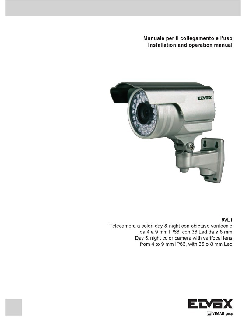
Elvox 5VL0 User manual

Manuale per il collegamento e l’uso
Installation and operation manual
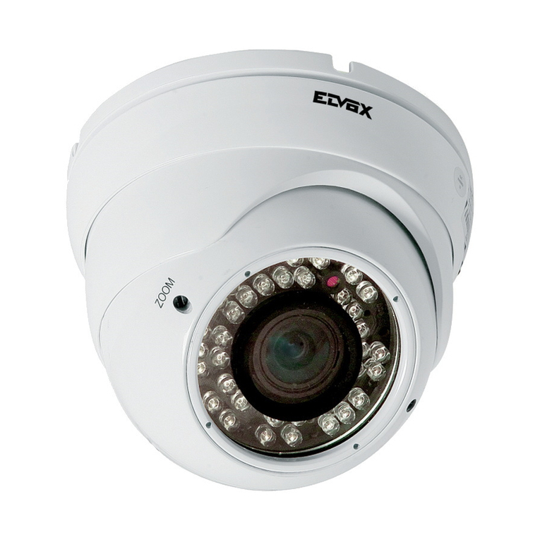
5VL0
Telecamera a colori day & night con obiettivo varifocal da 4 a 9 mm IP66. n° 36 Led da ø 5 mm
Day & night color camera with varifocal lens from 4 to 9 mm IP66. n° 36 Led ø 5 mm
IEN
Features:
SONY CCD
480 TV Lines
36 IR LED 5mm ø
IR Range 30m
4-9mm Vari-focus lens from Outer Change
Output cable from the bracket
Double glazing to limit contamination Infrared
Auto-activation of infrared control device
CDS in low light conditions
Caratteristiche:
CCD SONY
480 linee TV
36 LED IR da 5 mm ø
Portata IR 30 m
Lente Varifocale da 4-9 mm
Uscita cavo di collegamento dalla staffa
Doppi vetri per limitare i disturbi agli infrarossi
Auto-attivazione degli infrarossi con dispositivo di controllo
CDS in condizioni di bassa luminosità
Speciche:
Modello 5VL0
Sensore d’immagine CCD SONY da 1/3”
Elementi d’immagine ( H*V ) NTSC:510×492, PAL:500×582
Risoluzione orizzontale 480 linee TV
Rapporto segnale/rumore > 50dB
Frequenza di clock (MHZ) NTSC:19.0699 , PAL:18.9375
Sistema di scansione Interlacciato 2:1
Illuminazione minima 0 Lux (con LED IR accesi)
Sincronizzazione Sinc. negativa, interna
Otturatore elettronico automatico NTSC:1/60s~1/100,000s,PAL:1/50s~1/100,000s
Correzione di gamma 0,45
Portata IR 30 metri
Attivazione IR Sotto i 10 Lux con CDS
Accensione IR Controllo automatico CDS
Uscita video 1Vpp, 75 Ohm
Controllo di guadagno Automatico
Alimentazione 12 Vcc (±10%) / 500mA
Obiettivo 4-9 mm
Tenuta all’acqua IP66
Dimensioni (mm) 75ø x 145
Peso (g) 850
Temperatura di conservazione -30~ +60 °C UR 95% max
Temperatura di esercizio -10~ +45 °C UR 95% max
Model 5VL0
Pick Up Element SONY 1/3” CCD
Effective Picture Elements ( H*V ) NTSC:510×492, PAL:500×582
Horizontal Resolution 480 TV Lines
S/N Ratio More than 50dB
Clock Frequency (MHZ) NTSC:19.0699 , PAL:18.9375
Scanning System 2:1 interlace
Minimum Illumination 0 Lux (with IR LED ON)
Synchronous System Internal, Negative sync.
Auto Electronic Shutter NTSC:1/60s~1/100,000s,PAL:1/50s~1/100,000s
Gama Characteristic 0.45
IR Distance 30 Meters
IR Status Under 10 Lux by CDS
IR Power On CDS Auto Control
Video Output 1Vpp,75 Ohm
Auto Gain Control Auto
Power/Current 12VDC(±10%)/500mA
Lens 4-9 mm
Water Resistance IP66
Dimension (mm) 75ø x 145
Weight (g) 850
Storage Temperature -30~ +60 °C RH95% Max
Operating Temperature -10~ +45 °C RH95% Max
Specication:
IEN
Zoom Focus
N.B. Riposizionare i tappi nei fori dopo aver
eseguito le opportune regolazioni.
Note: place the covers in the holes after ma-
king the proper adjustments.
Monitor
Alimentazione 12Vdc 1,5A
12Vdc 1,5A supply
Video
GND
Staffa di montaggio
Mounting bracket
Alimentatore
Power supply
Art. 46902.015
-+
Connettore di alimentazione - Power supply connector
1. No Picture after providing power
- May be the power supply voltage abnormity, please check
the power supply voltage and pole whether exactitude.
- Please check all the connecting cable and monitors
whether be connected correctly or not.
2. The picture level direction have owing interference
ripples
- May be caused by the power supply AC ripples, it need
lter the wave of the power supply.
- Check the monitor and peripheral equipments used.
3. The picture background color changes continuously
- The uorescent lamp’s electromagnetic eld cause color
roll. This is proper phenomenon of the cameras.
- Reduce the uorescent lamp numbers or increase the di-
stance between the camera and the uorescent lamps can
improve it.
- Use power supply external sync. camera can solve it.
4. The picture smear too mass
- The power supply’s voltage unstable.
- Connecting cables not connect correctly or have high im-
pedance.
1. Con la telecamera alimentata non c’è l’immagine nel
monitor
- Controllare che non ci sia un sovraccarico nell’alimenta-
zione, vericare che la tensione e la polarità siano esatte.
- Vericare il collegamento del coassiale verso il monito.
2. L’immagine presenta oscillazioni
- La causa potrebbe essere data dall’alimentatore non ben
ltrato
- Controllare monitor ed apparati usati
3. Il colore di fondo dell’immagine cambia continua-
mente
-
Il campo elettromagnetico creato dalle lampade uorescenti
può causare questo inconveniente alla telecamera.
- Ridurre il numero delle lampade uorescenti oppure
aumentare la distanza tra la telecamera e le lampade,
questo può migliorare la situazione
- Oppure utilizzare altri tipi di telecamere che vengano sin-
cronizzate dall’alimentazione.
4. L’immagine perde di qualità
- La tensione di alimentazione non è stabilizzata.
- Il cavo coassiale non è collegato correttamente oppure
l’impedenza non è corretta.
ANOMALIE E POSSIBILI SOLUZIONI TROUBLE AND SOLUTION
Connettore segnale video - Video signal connector
Schema di collegamento - Wiring diagram:
Telecamera
Camera
Art. 5VL0
Video
12Vdc
Vimar SpA: Viale Vicenza, 14
36063 Marostica VI - Italy
Tel. +39 0424 488 600 - Fax (Italia) 0424 488 188
Fax (Export) 0424 488 709
www.vimar.com
49400813A0 00 15 04
VIMAR - Marostica - Italy
AVVERTENZE PER L’INSTALLATORE
- Leggere attentamente le avvertenze contenute nel presente documento in
quanto forniscono importanti indicazioni riguardanti la sicurezza di installa-
zione, d’uso e di manutenzione.
-
Dopo aver tolto l’imballaggio assicurarsi dell’integrità dell’apparecchio. Gli
elementi dell’imballaggio (sacchetti di plastica, polistirolo espanso, ecc.) non
devono essere lasciati alla portata dei bambini in quanto potenziali fonti di
pericolo. L’esecuzione dell’impianto deve essere rispondente alle norme CEI
vigenti.
- È necessario prevedere a monte dell’alimentazione un appropriato interrut-
tore di tipo onnipolare facilmente accessibile con separazione tra i contatti di
almeno 3mm.
- Prima di collegare l’apparecchio accertarsi che i dati di targa siano rispon-
denti a quelli della rete di distribuzione.
- Questo apparecchio dovrà essere destinato solo all’uso per il quale è stato
espressamente concepito, e cioè per sistemi di T.V.C.C.. Ogni altro uso è da
considerarsi improprio e quindi pericoloso. Il costruttore non può essere con-
siderato responsabile per eventuali danni derivanti da usi impropri, erronei ed
irragionevoli.
- Prima di effettuare qualsiasi operazione di pulizia o di manutenzione, disin-
serire l’apparecchio dalla rete di alimentazione elettrica, spegnendo l’inter-
ruttore dell’impianto.
- In caso di guasto e/o di cattivo funzionamento dell’apparecchio, togliere l’ali-
mentazione mediante l’interruttore e non manometterlo. Per l’eventuale ripa-
razione rivolgersi solamente ad un centro di assistenza tecnica autorizzato
dal costruttore. Il mancato rispetto di quanto sopra può compromettere la
sicurezza dell’apparecchio.
- Non ostruire le aperture o fessure di ventilazione o di smaltimento calore e
non esporre l’apparecchio a stillicidio o spruzzi d’acqua.
- L’installatore deve assicurarsi che le informazioni per l’utente siano presenti
sugli apparecchi derivati.
- Tutti gli apparecchi costituenti l’impianto devono essere destinati esclusiva-
mente all’uso per cui sono stati concepiti.
- ATTENZIONE: per evitare di ferirsi, questo apparecchio deve essere assicu-
rato alla parete secondo le istruzioni di installazione.
- Questo documento dovrà sempre rimanere allegato alla documentazione
dell’impianto.
Direttiva 2002/96/CE (WEEE, RAEE).
Il simbolo del cestino barrato riportato sull’apparecchio indica che il
prodotto, alla ne della propria vita utile, dovendo essere trattato se-
paratamente dai riuti domestici, deve essere conferito in un centro
di raccolta differenziata per apparecchiature elettriche ed elettroniche
oppure riconsegnato al rivenditore al momento dell’acquisto di una
nuova apparecchiatura equivalente.
L’utente è responsabile del conferimento dell’apparecchio a ne vita alle appro-
priate strutture di raccolta. L’adeguata raccolta differenziata per l’avvio succes-
sivo dell’apparecchio dismesso al riciclaggio, al trattamento e allo smaltimento
ambientalmente compatibile contribuisce ad evitare possibili effetti negativi
sull’ambiente e sulla salute e favorisce il riciclo dei materiali di cui è composto
il prodotto. Per informazioni più dettagliate inerenti i sistemi di raccolta disponi-
bili, rivolgersi al servizio locale di smaltimento riuti, o al negozio in cui è stato
effettuato l’acquisto.
Rischi legati alle sostanze considerate pericolose (WEEE).
Secondo la nuova Direttiva WEEE sostanze che da tempo sono utilizzate co-
munemente su apparecchi elettrici ed elettronici sono considerate sostanze
pericolose per le persone e l’ambiente. L’adeguata raccolta differenziata per
l’avvio successivo dell’apparecchio dismesso al riciclaggio, al trattamento e allo
smaltimento ambientalmente compatibile contribuisce ad evitare possibili effetti
negativi sull’ambiente e sulla salute e favorisce il riciclo dei materiali di cui è
composto il prodotto.
Il prodotto è conforme alla direttiva europea 2004/108/CE e successive.
SAFETY INSTRUCTIONS FOR INSTALLERS
- Carefully read the instructions on this leaet: they give important informa-
tion on the safety, use and maintenance of the installation.
- After removing the packing, check the integrity of the set. Packing compo-
nents (plastic bags, expanded polystyrene etc.) are dangerous for children.
Installation must be carried out according to national safety regulations.
- It is convenient to t close to the supply voltage source a proper ominipolar
type switch with 3 mm separation (minimum) between contacts.
- Before connecting the set, ensure that the data on the label correspond to
those of the mains.
- Use this set only for the purposes designed, i.e.for CCTV systems. Any
other use may be dangerous. The manufacturer is not responsible for da-
mage caused by improper, erroneous or irrational use.
- Before cleaning or maintenance, disconnect the set.
- In case of failure or faulty operation, disconnect the set and do not open it.
- For repairs apply only to the technical assistance centre authorized by the
manufacturer.
- Safety may be compromised if these instructions are disregarded.
- Do not obstruct opening of ventilation or heat exit slots and do not expose
the set to dripping or sprinkling of water.
- Installers must ensure that manuals with the above instructions are left on
connected units after installation, for users’ information.
- All items must only be used for the purposes designed.
- WARNING: to avoid the possibility of hurting yourself, this unit must be
xed to the wall according to the installation instructions.
- This leaet must always be enclosed with the equipment.
Directive 2002/96/EC (WEEE)
The crossed-out wheelie bin symbol marked on the product indi-
cates that at the end of its useful life, the product must be handled
separately from household refuse and must therefore be assigned
to a differentiated collection centre for electrical and electronic equi-
pment or returned to the dealer upon purchase of a new, equivalent
item of equipment.
The user is responsible for assigning the equipment, at the end of its life, to the
appropriate collection facilities.
Suitable differentiated collection, for the purpose of subsequent recycling of
decommissioned equipment and environmentally compatible treatment and di-
sposal, helps prevent potential negative effects on health and the environment
and promotes the recycling of the materials of which the product is made. For
further details regarding the collection systems available, contact your local
waste disposal service or the shop from which the equipment was purchased.
Risks connected to substances considered as dangerous (WEEE).
According to the WEEE Directive, substances since long usually used on
electric and electronic appliances are considered dangerous for people and
the environment. The adequate differentiated collection for the subsequent
dispatch of the appliance for the recycling, treatment and dismantling (com-
patible with the environment) help to avoid possible negative effects on the
environment and health and promote the recycling of material with which the
product is compound.
Product is according to EC Directive 2004/108/EC and following norms.
Other Elvox Security Camera manuals

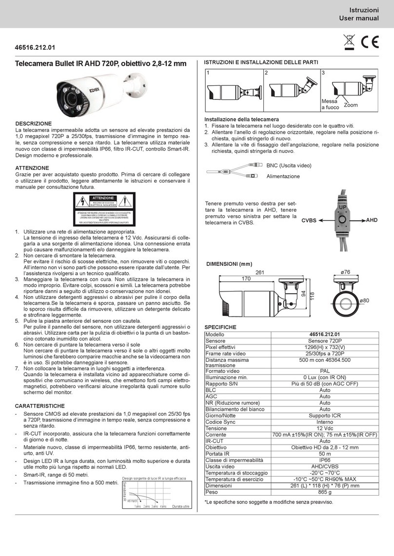
Elvox FW-V 3.00 User manual

Elvox

Elvox FW-V 3.00 User manual

Elvox 46516.212B User manual

Elvox

Elvox 46516.212B User manual

Elvox 46516.212.01 User manual

Elvox

Elvox 46516.212.01 User manual

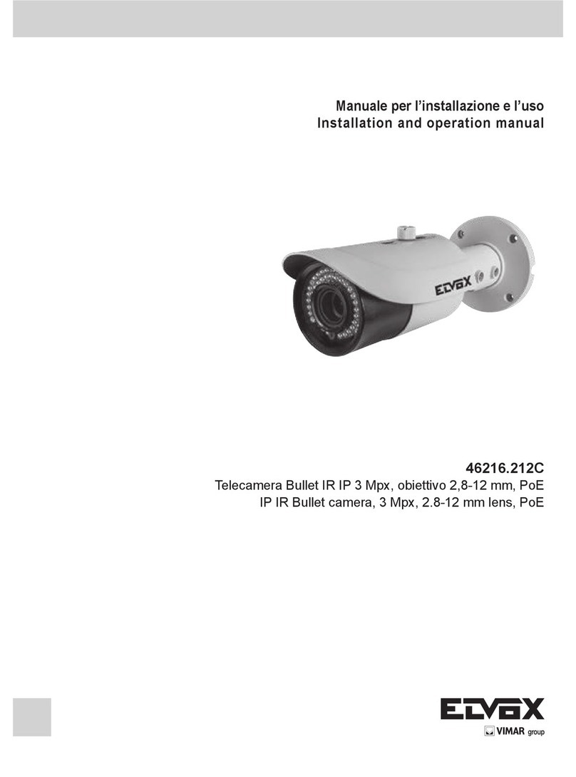
Elvox 46216.212C User manual

Elvox

Elvox 46216.212C User manual

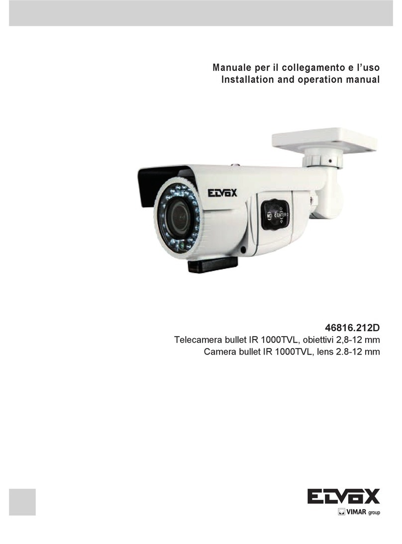
Elvox 46816.212D User manual

Elvox

Elvox 46816.212D User manual

Elvox 46237.036 User manual

Elvox

Elvox 46237.036 User manual

Elvox 68TC/K User manual

Elvox

Elvox 68TC/K User manual

Elvox 46816.212C User manual

Elvox

Elvox 46816.212C User manual

Elvox 46235.020 User manual

Elvox

Elvox 46235.020 User manual

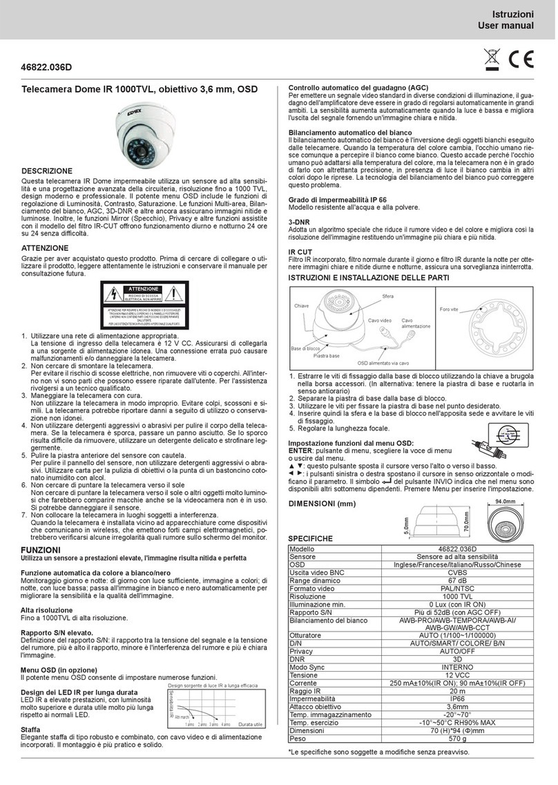
Elvox 46822.036D User manual

Elvox

Elvox 46822.036D User manual

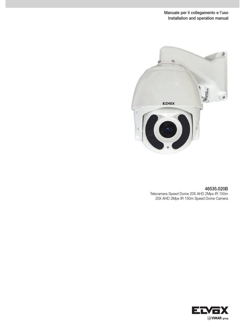
Elvox 46535.020B User manual

Elvox

Elvox 46535.020B User manual

Elvox 5VL4/660 User manual

Elvox

Elvox 5VL4/660 User manual

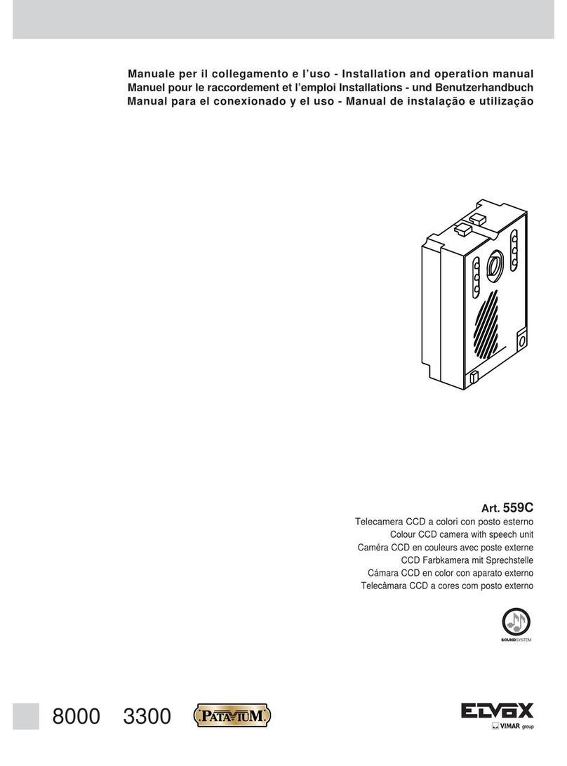
Elvox 559C User manual

Elvox

Elvox 559C User manual

Elvox 46826.212D User manual

Elvox

Elvox 46826.212D User manual

Elvox 5VL1 User manual

Elvox

Elvox 5VL1 User manual

Elvox 52L5 User manual

Elvox

Elvox 52L5 User manual

Popular Security Camera manuals by other brands

Idis DC-B1203X quick guide

Idis

Idis DC-B1203X quick guide

TRENDnet TV-IP602WN Quick installation guide

TRENDnet

TRENDnet TV-IP602WN Quick installation guide

ATIK Cameras 4000 quick start guide

ATIK Cameras

ATIK Cameras 4000 quick start guide

Axis Fixed Dome Network Camera AXIS P3301 user manual

Axis

Axis Fixed Dome Network Camera AXIS P3301 user manual

Wisenet PNM-9322VQP user manual

Wisenet

Wisenet PNM-9322VQP user manual

Amiccom Y12 user manual

Amiccom

Amiccom Y12 user manual

Zip IP-CAM890 instruction manual

Zip

Zip IP-CAM890 instruction manual

Foscam FI9821P user manual

Foscam

Foscam FI9821P user manual

Honeywell Lyric C1 Quick installation guide

Honeywell

Honeywell Lyric C1 Quick installation guide

Axis AXIS Q8721-E installation guide

Axis

Axis AXIS Q8721-E installation guide

Speco O8FB1M quick start guide

Speco

Speco O8FB1M quick start guide

Vitek VTC-TNB8RMA4B quick start guide

Vitek

Vitek VTC-TNB8RMA4B quick start guide

OpenEye OE-C1011D4 user manual

OpenEye

OpenEye OE-C1011D4 user manual

Eyeris ERN-R3645N Installation and operating instruction manual

Eyeris

Eyeris ERN-R3645N Installation and operating instruction manual

Doss L Series user manual

Doss

Doss L Series user manual

Axis P14 Series Repainting instructions

Axis

Axis P14 Series Repainting instructions

urmet domus 1092/132 instructions

urmet domus

urmet domus 1092/132 instructions

Triax TDV IP manual

Triax

Triax TDV IP manual

manuals.online logo
manuals.online logoBrands
  • About & Mission
  • Contact us
  • Privacy Policy
  • Terms and Conditions

Copyright 2025 Manuals.Online. All Rights Reserved.