Elvox 68TC/K User manual

Art. 68TC/K, 68TU/K
TELECAMERA CCD CON POSTO ESTERNO PER PER VI-
DEOKIT 2 FILI E TARGA 13K1
CCD CAMERA WITH SPEECH UNIT FOR 2-WIRE VIDEO-
KIT AND PANEL 13K1
CAMÉRA CCD AVEC POSTE EXTÉRIEUR POUR VIDEO-
KIT 2 FILS ET PLAQUE 13K1
Il prodotto è conforme alla direttiva europea 2004/108/CE, 2006/95/CE e successive.
Product is according to EC Directive 2004/108/CE, 2006/95/CE and following norms.
Le produit est conforme à la directive européenne 2004/108/CE, 2006/95/CE et suivantes.
Das Produkt entspricht den europäischen Richtlinien 2004/108/CE, 2006/95/CE und Nachfolgenden.
El producto es conforme a la directiva europea 2004/108/CE, 2006/95/CE y sucesivas.
O produto está conforme a directiva europeia 2004/108/CE, 2006/95/CE e seguintes.
PDGB EFI
MANUALE PER IL COLLEGAMENTO E L’USO - INSTALLATION AND OPERATION MANUAL - MANUEL POUR LA CONNEXION ET L’EMPLOI
INSTALLATION UND BEDIENUNGSANLEITUNG - MANUAL PARA EL CONEXIONADO Y EL USO - MANUAL DE INSTALAÇÃO E UTILIZAÇÃO
8/2011RL.01
Cod. S6I.68T.CK0
CCD-KAMERA MIT AUSSENSTELLE FÜR VIDEOKIT 2
FILI UND KLINGELTABLEAU 13K1
CÁMARA CCD CON APARATO EXTERNO PARA VIDEO-
KIT 2 FILI Y PLACA 13K1
TELECÂMARA CCD COM POSTO EXTERNO PARA KIT
VÍDEO 2 FILI E BOTONEIRA 13K1

Morsetti della telecamera Art. 68TU/K, 68TC/K
CL, M) Collegamento per relè Art. 170/101 (per eventuale accensione di una
illuminazione della zona di ripresa). Si attiva per il periodo di accen-
sione della telecamera.
CA, M) Collegamento per pulsante apriporta supplementare.
PA, M) Collegamento per sensore porta aperta. Il sensore dev’essere un
contatto normalmente aperto che si chiude quando la porta è aperta.
B1, B2) Linea BUS
S-, S+) Uscita per alimentazione serratura elettrica (12V ).
V) (Non utilizzato) *
Telecamera 1
IT=0
(Default)
Telecamera 2
IT=1
La targa fornisce un picco di corrente IT> 1A per 10 mS dopo il quale
segue una corrente di mantenimento IM= 200mA per tutta la durata del
comando serratura.
Codice di identificazione TARGA/TELECAMERA
Quando nell’impianto ci sono più telecamere/targhe è necessario identi-
ficare le telecamere con un codice di identificazione diverso. Il codice di
identificazione viene assegnato tramite l’inserzione dei ponticelli nei con-
tatti come indicato in figura.
*
TELECAMERE Art. 68TU/K, 68TC/K
Telecamere a colori (Art. 68TC/K) e in B/N (Art. 68TU/K) da utilizzare con
targa serie 1300 (Art. 13K1) per impianti videokit 2 fili.
Caratteristeche tecniche della telecamera (Art. 68TU/K)
- Sensore CCD 1/3" in B/N.
- Obiettivo 3,7 mm F4,0 a fuoco fisso
- Controllo automatico della luminosità.
- Brandeggiabile manualmente sull'asse verticale e orizzontale
- Segnale video standard CCIR 625 linee 50 quadri (a richiesta standard
EIA).
- Temperatura di funzionamento da -5° a + 45° C.
- Illuminazione soggetto tramite LED all'infrarosso
- Illuminazione cartellino portanome tramite LED
- Posto esterno audio incorporato
- Morsettiera per il collegamento estraibile.
- Pulsante di chiamata videocitofono.
- Uscita per comando faretto illuminazione tramite relè Art. 170/101.
- Comando apriporta locale da targa.
- Tempo attivazione serratura regolabile (da 0 a 30 secondi).
- Alimentazione data dal bus.
- Dimensioni di ingombro massime 80x120x25 mm.
Caratteristeche tecniche della telecamera (Art. 68TC/K)
- Sensore CCD 1/3" a colori
- Obiettivo autoiride fuoco fisso 3,7mm F4,0
- Segnale video standard PAL tipo G, 625 linee, 50 quadri.
- Brandeggiabile manualmente sull'asse verticale e orizzontale
- Numero elementi sensore 512 (H) x 582 (V)
- Risoluzione verticale: maggiore di 330 linee
- Diaframma elettronico (shutter).
- Temperatura di funzionamento da -5° a + 45° C.
- Livello di illuminazione al soggetto minimo 0,1 lux
- Illuminazione soggetto con LED a luce bianca
- Illuminazione cartellino portanome tramite LED
- Posto esterno audio incorporato
- Morsettiera per il collegamento estraibile.
- Pulsante di chiamata videocitofono.
- Uscita per comando faretto illuminazione tramite relè Art. 170/101.
- Comando apriporta locale da targa.
- Tempo attivazione serratura regolabile (da 0 a 30 secondi).
- Alimentazione data dal bus.
- Dimensioni di ingombro massime 80x120x25 mm.
Regolazioni telecamera (Art. 68TU/K, 68TC/K)
Sul retro della telecamera sono presenti le seguenti regolazioni:
Volume
esterno
Tempo attivazione
telecamera
Volume
interno
Tempo attivazione
serratura
Fig.12
Microfono
1° Pulsante
da utilizzare
LED di illuminazione
cartellino portanomi
Fig.13
2° Pulsante
da utilizzare
LED di illuminazione
cartellino portanomi
LED CH2
12V
Art. 68TC/K, 68TU/K
TEMPI DI FUNZIONAMENTO
Il monitor, la telecamera, la serratura e servizi ausiliari devono funzionare
con i seguenti cicli di intermittenza.
Ciclo accensione monitor e telecamera:
90 secondi massimi acceso, 90 secondi spento
Ciclo serratura:
1 secondo massimo attiva, 5 secondi disattiva
Ciclo servizi ausiliari
90 secondi massimi attivo, 90 secondi disattivo.
2/32
I

Vite di fissaggio
Fig.14A
Fig.14B
Orientamento obiettivo
La telecamera Art. 68TU/K (68TC/K) può essere regolata manualmente sul-
l'asse verticale e orizzontale per un miglior angolo di ripresa; allentare la vite
al di sopra dell’obiettivo, ruotare lo stesso nella direzione voluta, fissare la
vite.
INSTALLAZIONE GENERALE TARGHE PER VIDEOCITOFONO
All'atto dell'installazione è opportuno scegliere la posizione del gruppo
esterno di ripresa in modo che non sia investito direttamente da fonti lumi-
nose (sole, lampioni, fari di macchine ecc.). Il soggetto da riprendere deve
essere illuminato frontalmente in modo da evitare la ripresa in controluce. La
telecamera è dotata di LED per illuminazione notturna del soggetto fino a
circa 1 metro di distanza.
Art. 68TC/K, 68TU/K
Installazione della targa (art. 13K1) in versione da incasso parete
- Installare a muro la scatola da incasso (D) ad una altezza di circa 1,65m
dal bordo superiore dalla scatola al pavimento
- Aprire la targa svitando la vite sotto alla placca (G) e staccare la teleca-
mera (B) dal telaio, togliendo il diffusore di luce (H) e il microfono (I).
- Fissare il telaio (C) alla scatola da incasso (D)
- Riposizionare la telecamera nel telaio e il microfono nell’apposito alloggia-
mento richiudendo il tappo come indicato nella fig.16A.
- Collegare la telecamera alla scheda LED di illuminazione cartellini porta-
nome mediante i due cablaggi (cablaggio con fili rosso/nero per alimen-
tazione LED e cablaggio con due fili verdi per il collegamento
dell’eventuale secondo pulsante di chiamata) fig.16B.
- Effettuare sulla morsettiera estraibile (L) i collegamenti all’impianto.
Nel caso di installazione per impianto videocitofonico bifamiliare, si deve:
- Togliere il modulo copriforo (E) fig. 17, dal retro della placca, con l’impiego
di un cacciavite, rispettando la sequenza dal basso verso l’alto (si deve to-
gliere prima la testata, poi il 1° tasto e in fine modulo copriforo.
- Fissare alla placca il tasto esterno (F) (fornito in dotazione), facendo una
leggera pressione.
- Inserire il diffusore di luce (H) per rendere uniforme l’illuminazione dei car-
tellini portanome.
- Chiudere la targa fissandola al telaio per mezzo di un cacciavite.
B
C
D
I
N
Fig.15
A
H
G
O
L
M
I
3/32

B
C
P
N
O
L
Fig.18
M
E
(Art. R130)
(Art. R135)
F
Fig.17
1
2
3
I
H
G
A
- Effettuare sulla morsettiera estraibile (L) i collegamenti all’impianto.
Nel caso di installazione per impianto videocitofonico bifamiliare, si deve:
- Togliere il modulo copriforo (E) fig. 17, dal retro della placca, con
l’impiego di un cacciavite, rispettando la sequenza dal basso verso
l’alto (si deve togliere prima la testata, poi il 1° tasto e in fine modulo
copriforo.
- Fissare alla placca il tasto esterno (F) (fornito in dotazione), facendo
una leggera pressione.
- Inserire il diffusore di luce (H) per rendere uniforme l’illuminazione dei
cartellini portanome.
- Chiudere la targa fissandola al telaio per mezzo di un cacciavite.
Installazione della targa (art. 13K1) in versione da esterno parete
- Aprire la targa svitando la vite sotto alla placca (G) e staccare la te-
lecamera (B) dal telaio, togliendo il diffusore di luce (H) e il micro-
fono (I).
- Installare a muro il telaio (C) unito alla la scatola da esterno (P) ad
una altezza di circa 1,65m dal bordo superiore dalla scatola al pa-
vimento.
- Riposizionare la telecamera nel telaio e il microfono nell’apposito
alloggiamento posto (B) richiudendo il tappo come indicato nella
fig. 16A.
- Collegare la telecamera alla scheda LED di illuminazione cartellini
portanome mediante i due cablaggi (cablaggio con fili rosso/nero
per alimentazione LED e cablaggio con due fili verdi per il collega-
mento dell’eventuale secondo pulsante di chiamata) fig.16B.
IArt. 68TC/K, 68TU/K
4/32
Fig.16A
LED CH2
12V
Fig.16B
Cablaggio rosso/nero
Cablaggio verde/verde

I
COLLEGAMENTI
Videokit art. 68IA/R ( bianco e nero) , Art. 68IA/RC ( a colori)
- I due fili di collegamento tra alimentatore e monitor e tra alimentatore e targa
possono essere invertiti di polarità.
- Il cavo consigliato per il collegamento del kit è Art. 732H (2X1mm²) e/o 732I
( 2X1mm²). Se il cavo utilizzato non è tra quelli indicati NON si garantisce
quanto descritto in seguito.
-L’impianto è garantito per una distanza massima di metri 150. Distanza
intesa in linea tra 2 dispositivi, i più distanti tra loro (es. targa più di-
stante e monitor più distante). La totale metratura di cavo steso non
deve superare metri 500. Queste distanze massime sono da conside-
rarsi valide sia per gli impianti in b/n sia a colori.
- Le serrature elettriche collegate alle targhe dovranno avere un assorbimento
massimo di 1 A alla tensione di 12 Vcc.
- Disturbi o scariche elettriche possono ripercuotersi sul buon funzionamento
delle apparecchiature. Pertanto si consiglia la posa dei cavi all’interno di tu-
bazioni separate.
B2
C2
B1
C1
A1
A2
A1 + A2 + B1 + B2 = Max 150 m
A1 + A2 + C1 + C2 = Max 150 m
Art. 68TC/K, 68TU/K
5/32

GB
6/32
Art. 68TC/K, 68TU/K
OPERATING DWELL TIME
The monitor, camera, door lock and auxiliary services mut operate accor-
ding to the following intermittent cycles.
Monitor and camera activation cycle:
max. 90 seconds activated, 90 seconds deactivated
Door lock cycle:
max. 1 second activated, 5 seconds deactivated
Auxiliary service cycle:
max. 90 seconds activated, 90 seconds deactivated
Camera terminals type 68TU/K, 68TC/K
CL, M) Connection for relay type 170/101 for additional floodlight.
(for switching on illumination in the camera's observation zone)
It is activated for the time the camera is on.
CA, M) Connection for additional lock push-button.
PA, M) Connection for "open door" sensor. The sensor must be a nor-
mally open contact which closes when the door is open.
B1, B2) BUS line
S-, S+) Output for electric lock supply voltage (12V ).
V) (Not used) *
The panel supplies a current peak IT> 1A for 10 mS, followed by a hold
current IM= 200mA for the entire duration of the lock control.
*
CAMERA Type 68TU/K, 68TC/K
Colour cameras (type 68TC/K) and B/W cameras (type 68TU/K) for use with
1300 series panel (type 13K1) for 2-wire videokit installations.
Camera technical features (Type 68TU/K)
- CCD 1/3" color sensor B/W
- 3,7mm F4.0 auto-iris lens with non-adjustable focus
- Automatic brightness control
- Manual traversing on the vertical and horizontal axis
- Standard video signal CCIR 625 lines, 50 images (EIA on request)
- Operating temperature from - 5° to + 45° C.
- Subject lighting by means of infrared LEDs
- Name-tag lighting through LEDs
- Built-in speech unit
- Removable terminal block
- Monitor call push-button.
- Output for control of lighting floodlight by relay type 170/101
- Local door release control from entrance panel.
- Adjustable lock activation time (from 0 to 30 seconds).
- Supply voltage from the bus.
- External dimensions: 80x120x25 mm.
Camera technical features (Art. 68TC/K)
- Sensore CCD 1/3" a colori
- Obiettivo autoiride fuoco fisso 3,7mm F4,0
- Standard video signal PAL type G, 625 lines, 50 images
- Manual traversing on the vertical and horizontal axis
- Vertical resolution: 330 TV lines or Greater
- Effective picture: 512(H)x582(V) PAL
- Electronic iris (shutter)
- Video output voltage 1Vpp on 75 Ohms
- Operating temperature -5° +45°C
- Minimum lighting level 0,1 lux
- Subject lighting by means of white light LEDs
- Name-tag lighting through LEDs
- Built-in speech unit
- Removable terminal block
- Monitor call push-button.
- Output for control of lighting floodlight by relay type 170/101
- Local door release control from entrance panel.
- Adjustable lock activation time (from 0 to 30 seconds).
- Supply voltage from the bus.
- External dimensions: 80x120x25 mm.
Camera adjustments (Art. 68TU/K, 68TC/K)
On the camera rear side find the following adjustments:
Lock activation
time
External
volume
Internal
volume Camera activation
time
1st camera
IT=0
(Default)
2nd camera
IT=1
ENTRANCE PANEL/CAMERA identification code
If more cameras/entrance panels are installed on the building it is necessary
to identify the cameras with a different code. The identification code is assi-
gned by inserting the jumpers in the contacts as shown on the figure.
Fig.12
Microphone
1st push-button
Name tag lighting
LED
Fig.13
2nd push-button
Name tag lighting
LED
LED CH2
12V

7/32
GB
Art. 68TC/K, 68TU/K
B
C
D
I
N
Fig.15
A
H
G
O
L
M
Fixing screw
Fig.14A
Fig.14B
Lens orientation
Camera unit Type. 68TU/K (68TC/K) can be adjusted manually on the verti-
cal and horizontal axis to improve the shooting angle, the screw on the
upper side of the lens loosen, turn the lens in the required direction and fix
the screw.
ENTRANCE PANEL FOR VIDEO DOOR ENTRY SYSTEMS
Before installing equipment, choose location for camera entrance panel: the
camera shouid be protected from direct light (sun, car headlights, etc.) as
this may affect the quality of the picture, and may damage the camera. It is
advisable to protect panel with some form of weatherproof shelter.
The video camera is equipped with LEDs for night illumination of the sub-
ject up to a distance of 1 metre approx.
Installation of entrance panel (type 13K1), flush-mounting version
- Install the flush-mounting back box (D) on the wall with the bottom edge
at a height of approx. 1.65m from the ground
- Open the entrance panel by undoing the screw under the plate (G) and de-
tach the camera (B) from the frame, removing the light diffuser (H) and the
microphone (I).
- Fit the frame (C) to the flush-mounting back box (D)
- Reposition the camera in the frame and the microphone in the special hou-
sing, refitting the plug as shown in fig.16A.
- Connect the camera to the name card lighting LED board using the two
cable harnesses (harness with red/black wire for LED power supply and
harness with two green wires for connection of a second call button, if re-
quired) fig.16B.
- Make the connections to the installation on the removable terminal block
(L).
In the case of installation for two-family video door entry systems:
- Remove the blanking module (E) fig. 17, from the back of the plate using
a screwdriver, working in sequence from bottom to top (first remove the
end section, then key 1 and finally the blanking module).
- Fit the external key (F) (supplied) to the plate by pushing it lightly into place.
- Insert the light diffuser (H) to ensure even lighting of the name cards.
- Close the entrance panel, securing it to the frame with the aid of a screw-
driver.

GB
8/32
Art. 68TC/K, 68TU/K
B
C
P
N
O
L
Fig.18
M
Fig.16A
E
(Art. R130)
(Art. R135)
F
Fig.17
1
2
3
I
H
G
A
- Make the connections to the installation on the removable terminal
block (L).
In the case of installation for two-family video door entry systems:
- Remove the blanking module (E) fig. 17, from the back of the plate using
a screwdriver, working in sequence from bottom to top (first remove the
end section, then key 1 and finally the blanking module.
- Fit the external key (F) (supplied) to the plate by pushing it lightly into
place.
- Insert the light diffuser (H) to ensure even lighting of the name cards.
- Close the entrance panel, securing it to the frame with the aid of a
screwdriver.
LED CH2
12V
Fig.16B
Red/black cable
Green/green cable
Installation of entrance panel (type 13K1), surface wall-mounting version
- Open the entrance panel by undoing the screw under the plate (G) and
detach the camera (B) from the frame, removing the light diffuser (H)
and the microphone (I).
- Install the frame (C) together with the surface wall-mounting back box
(P) on the wall with the bottom edge at a height of approx. 1.65m from
the ground.
- Reposition the camera in the frame and the microphone in the special
housing (B), refitting the plug as shown in fig. 16A.
- Connect the camera to the name card lighting LED board using the two
cable harnesses (harness with red/black wire for LED power supply and
harness with two green wires for connection of a second call button, if
required) fig.16B.

9/32
GB
Art. 68TC/K, 68TU/K
B2
C2
B1
C1
A1
A2
WIRING DIAGRAM
Videokit type 68IA/R (black/white), type 68IA/RC (colour)
- It is possible to reverse the polarity of the two connecting wires bet-
ween power supply unit and monitor and between power supply unit
and entrance panel.
- The cable recommended for connecting the kit is type 732H (2x1mm²)
and/or 732I ( 2x1mm²). If the cable used is not one of those indicated
above, the following guarantees do NOT apply.
- The installation is guaranteed up to a maximum distance of 150 me-
tres. Distance intended as the straight-line distance between the 2
devices furthest apart (e.g. the furthest entrance panel and the fur-
thest monitor). The total length of extended cable must not exceed
500 metres. These maximum distances apply to both B/W and co-
lour installations.
- Electric locks connected to the entrance panels must have a maxi-
mum input current of 1 A at a voltage of 12 Vdc.
- Electrical disturbances or discharges may affect the operation of the
devices. Therefore we recommend laying the cables inside separate
tubes.
A1 + A2 + B1 + B2 = Max 150 m
A1 + A2 + C1 + C2 = Max 150 m

F
10/32
Art. 68TC/K, 68TU/K
TEMPS DE FONCTIONNEMENT:
Le moniteur, la caméra, la gâche et les services auxiliaires doivent fonction-
ner selon les cycles d'intermittance suivants:
Cycle enclenchement moniteur et caméra
90 secondes (max) activé, 90 secondes désactivé
Cycle gâche
1 seconde activé (max), 5 secondes désactivé
Cycle services auxiliaires
90 secondes activé (max), 90 secondes déactivé
Bornes de la caméra Art. 68TU/K, 68TC/K
CL, M) Raccordement pour relais Art. 170/101 (pour éventuel allumage
d'un éclairage de la zone de filmage) pour projecteur éclairage sup-
plémentaire. Il est activé pour la période d'enclenchement de la ca-
méra.
CA,M) Raccordement pour poussoir ouvre-porte supplémentaire.
PA, M) Raccordement pour senseur " porte ouverte ", le senseur doit avoir
un contact normalement ouverte qui se ferme lorsque la porte est
ouverte.
B1, B2) Ligne BUS
S-, S+) Sortie pour alimentation gâche électrique (12V ).
*
La plaque fournit un pic de courant IT> 1A pendant 10 mS qui est suivi
d'un courant de maintien IM= 200mA pendant toute la durée de la com-
mande serrure.
*
CAMERA Art. 68TU/K, 68TC/K
Caméras couleurs (Art. 68TC/K) et B/N (Art. 68TU/K) à utiliser avec plaque
série 1300 (Art. 13K1) pour installations videokits 2 fils.
Caracteristiques techniques de la camera (ART. 68TU/K)
- Senseur CCD 1/3" couleurs
- Objectif à diaphragme automatique 3,7mm F4,0 focus fixe
- Contrôle automatique de la luminosité
- Pivotement manuel sur l’axe vertical et horizontal
- Signal vidéo standard PAL type G, 625 lignes, 50 images
- Température de fonctionnement -5° + 45° C
- Éclairage sujet au moyen de LEDs à lumière blanche
- Éclairage porte-noms au moyen de LEDs
- Poste externe audio incorporé
- Boîte de raccordement amovible
- Poussoir appel moniteur
- Sortie pour commande projecteur éclairage au moyen de relais Art.
170/101.
- Commande ouvre-porte local depuis plaque de rue.
- Temps activation gâche réglable (de 0 à 30 secondes).
- Alimentation donnée par le bus.
- Dimensions maximum externes: 80x120x25 mm.
Caracteristiques techniques de la camera (ART. 68TC/K)
- Senseur CCD 1/3” B/N
- Objectif 3,7 mm F4,0 avec focus fixe
- Signal vidéo standard PAL type G, 625 lignes, 50 images
- Pivotement manuel sur l’axe vertical et horizontal
- Dimensiones reales de l’image: 512(H)x582(V) PAL
- Resolution horizontale: 330 Lignes TV ou plus grande
- Diaphragme électronique (shutter).
- Température de fonctionnement - 5° + 45° C
- Niveau d’éclairage minimum 0,1 lux.
- Éclairage sujet au moyen de LEDs à l'infrarouge
- Éclairage porte-noms au moyen de LEDs
- Poste externe audio incorporé
- Boîte de raccordement amovible
- Poussoir appel moniteur
- Sortie pour commande projecteur éclairage au moyen de relais Art.
170/101.
- Commande ouvre-porte local depuis plaque de rue.
- Temps activation gâche réglable (de 0 à 30 secondes).
- Alimentation donnée par le bus.
- Dimensions maximum externes : 80x120x25 mm.
Réglages caméra (Art. 68TU/K, 68TC/K)
À l'arrière de la caméra il y a le réglages suivants:
Temps activation
gâche
Temps activation
camera
Volume
interne
Volume
externe
1ère Caméra
IT=0
(Default)
2ème Caméra
IT=1
Code d’identification PLAQUE DE RUE/CAMERA
Lorsque dans une intallation il y a plusieurs caméras/plaques de rue il faut
mieux identifier la camera avec un code différent des autres. Le code
d’indentification est assigné au moyen de l’insertion des pontets dans les
contacts selon la figure.
Fig.12
Microphone
1er bouton à utiliser
LED d'éclairage éti-
quette porte-noms
Fig.13
2ème bouton-poussoir
LED d'éclairage éti-
quette porte-noms
LED CH2
12V
11/32
F
Art. 68TC/K, 68TU/K
Fig.14A
Fig.14B
B
C
D
I
N
Fig.15
A
H
G
O
L
M
Orientation objectif
Le unité de prise de vue Art. 68TU/K (68TC/K) peut être réglé manuellement
sur l’axe vertical et horizontal pour un meilleur angle de prise de vue,
dévisser la vis qui se trouve au-dessus de l'objectif, tourner le même dans
la direction voulue et fixer la vis.
INSTALLATION DE LA PLAQUE POUR PORTIER-VIDÉO
Au moment de l'installation il vaut mieux choisir la position de la plaque de
rue de façon que la caméra ne soit pas frappée directement par des fais-
seaux lumineux (soleil, phares d'auto etc.). Le sujet à prendre doit être il-
luminé en face pour éviter la prise de vue en contre-jour. La caméra est
équipée de leds pour l'éclairage nocturne de la personne jusqu'à 1 mètre
environ de distance.
Installation de la plaque (art. 13K1) en version à encastrer
- Installer la boîte d'encastrement (D) à une hauteur d'environ 1,65m du bord
supérieur de la boîte au sol
- Ouvrir la plaque de rue en dévissant la vis sous la façade (G) et détacher la
caméra (B) du châssis, en ôtant le diffuseur de lumière (H) et le microphone
(I).
- Fixer le châssis (C) à la boîte d'encastrement (D)
- Repositionner la caméra dans le châssis et le microphone dans le logement
spécial en refermant le bouchon comme indiqué sur la fig. 16A.
- Relier la caméra à la carte leds d'éclairage étiquettes porte-noms au moyen
des deux câblages (câblage avec fils rouge/noir pour l'alimentation led et
câblage avec deux fils verts pour la connexion de l'éventuel second bouton
d'appel) fig. 16B.
- Effectuer sur le bornier amovible (L) les branchements à l'installation. En cas
d'installation pour système visiophonique deux appartements il faut :
- Retirer le module cache-trou (E) fig. 17 depuis le dos de la façade, en utili-
sant un tournevis et en respectant la séquence du bas vers le haut (retirer
tout d'abord le chant puis la première touche et enfin le module cache-trou).
- Fixer à la façade la touche externe (F) (fournie) en appuyant légèrement.
- Insérer le diffuseur de lumière (H) pour rendre l'éclairage des étiquettes
porte-noms uniforme.
- Fermer la plaque en la fixant au châssis au moyen d'un tournevis.
Vis de fixation

F
12/32
Art. 68TC/K, 68TU/K
B
C
P
N
O
L
Fig.18
M
E
(Art. R130)
(Art. R135)
F
Fig.17
1
2
3
I
H
G
A
- Effectuer sur le bornier amovible (L) les branchements à l'installation.
En cas d'installation pour système visiophonique deux appartements il
faut :
- Retirer le module cache-trou (E) fig. 17 depuis le dos de la façade, en
utilisant un tournevis et en respectant la séquence du bas vers le haut (re-
tirer tout d'abord le chant puis la première touche et enfin le module
cache-trou).
- Fixer à la façade la touche externe (F) (fournie) en appuyant légèrement.
- Insérer le diffuseur de lumière (H) pour rendre l'éclairage des étiquettes
porte-noms uniforme.
- Fermer la plaque en la fixant au châssis au moyen d'un tournevis.
Installation de la plaque (art. 13K1) en version en saillie
- Ouvrir la plaque de rue en dévissant la vis sous la façade (G) et dé-
tacher la caméra (B) du châssis, en ôtant le diffuseur de lumière (H)
et le microphone (I).
- Installer le châssis (C) au mur avec la boîte pour le montage en sail-
lie (P) à une hauteur d'environ 1,65m du bord supérieur de la boîte
au sol.
- Repositionner la caméra dans le châssis et le microphone dans le lo-
gement spécial (B) en refermant le bouchon comme indiqué sur la
fig. 16A.
- Relier la caméra à la carte leds d'éclairage étiquettes porte-noms
au moyen des deux câblages (câblage avec fils rouge/noir pour
l'alimentation led et câblage avec deux fils verts pour la connexion
de l'éventuel second bouton d'appel) fig. 16B.
Fig.16A
LED CH2
12V
Fig.16B
Cablage rouge/noir
Cablage green/green

13/32
F
Art. 68TC/K, 68TU/K
B2
C2
B1
C1
A1
A2
A1 + A2 + B1 + B2 = Max 150 m
A1 + A2 + C1 + C2 = Max 150 m
CONNEXION
Kit vidéo art. 68IA/R (noir et blanc), Art. 68IA/RC (couleur)
- Les deux fils de connexion entre l'alimentation et le moniteur et entre
l'alimentation et la plaque peuvent être inversés de polarité.
- Le câble conseillé pour la connexion du kit est l'Art. 732H (2X1mm²) et/ou
732I ( 2X1mm²). Si le câble utilisé n'est pas parmi ceux indiqués, les points
ci-dessous NE sont PAS garantis .
- L'installation est garantie pour une distance maximum de 150 mètres. Di-
stance entendue en ligne entre 2 dispositifs, les plus éloignés entre eux
(ex. plaque la plus éloignée et moniteur le plus éloigné). Le métrage total
du câble tendu ne doit pas dépasser 500 mètres. Ces distances maxi-
mums sont valables tant pour les installations en n/b qu'en couleur.
- Les gâches électriques reliées aux plaques devront avoir une absorption
maximum de 1 A à la tension de 12 Vcc.
- Les perturbations ou les décharges électriques peuvent se répercuter sur
le fonctionnement correct des équipements. Par conséquent, il est con-
seillé de poser les câbles à l'intérieur de tuyauteries séparées.

D
14/32
Art. 68TC/K, 68TU/K
BETRIEBSDAUER
Monitor, Kamera, Türöffner und Zusatzfunktionen müssen in Bezug auf fol-
gende periodische Zyklen arbeiten.
Monitor und Kamera Einschaltzyklus:
Max. 90 Sekunden aktiviert, 90 Sekunden deaktiviert
Türöffnerzyklus:
Max. 1 Sekunde aktiviert, 5 Sekunden deaktiviert
Zusatzfunktionszyklus:
Max. 90 Sekunden aktiviert, 90 Sekunden deaktiviert
KAMERA Art. 68TU/K, 68TC/K
Farb- (Art. 68TC/K) und S/W-Kameras (Art. 68TU/K) zur Verwendung mit
Klingeltableau Serie 1300 (Art. 13K1) für Anlagen Videokit 2 Fili.
Technische eigenschaften der Kamera (Art. 68TU/K)
- CCD 1/3" B/W Farbsensor .
-Fixobjektiv 3,7 mm F4,0
- Automatische Helligkeitsregelung
- Objektiv horizontal und vertikal manuell einstellbar
- Standard Videosignal CCIR 625 Zeilen 50 Bilder (EIA auf Anfrage)
- Betriebstemperatur von - 5° bis + 45° C
- Beleuchtung durch Infrarot-LEDs
- Namensschildbeleuchtung durch LED
- Eingebaute Sprechstelle
- Abnehmbare Klemmenleiste
- Monitorruftaste
- Ausgang für Beleuchtungsscheinwerfer mittels Relais Art. 170/101.
- Lokale Türöffner-Steuerung von Klingeltableau.
- Einstellbare Aktivierungszeit des Schlosses (0 bis 30 Sekunden).
- Versorgung vom Bus
- Abmessungen: 80x120x25 mm.
Technische eigenschaften der Kamera (Art. 68TC/K)
- 1/3" CCD-Farbsensor
-Fixobjektiv mit Auto-Iris 3,7mm F4,0
-Videosignal Standard PAL Typ G, 625 Linien, 50 Bilder
-Objektiv horizontal und vertikal manuell einstellbar
-Bildabmessungen: 512(H)x582(V)
-Verticalauflösung: 330 TV-Linien oder mehr
- Elektronische Blende (Shutter).
- Betriebstemperatur von -5° bis + 45°C
- Mindestbeleuchtung 0,1 Lux
- Beleuchtung durch Weißlicht-LEDs
- Namensschildbeleuchtung durch LED
- Eingebaute Sprechstelle
- Abnehmbare Klemmenleiste
- Monitorruftaste
- Ausgang für Beleuchtungsscheinwerfer mittels Relais Art. 170/101. .
- Lokale Türöffner-Ansteuerung vom Klingeltableau.
- Einstellbare Aktivierungszeit des Türöffners (0 bis 30 Sekunden).
- Versorgung vom Bus
- Abmessungen: 80x120x25 mm.
Einstellungen an der Kamera (Art. 68TU/K, 68TC/K)
Auf der Kamerarückseite befinden sich die folgenden Einstellungsregler:
1. Kamera
IT=0
(Default)
2. Kamera
IT=1
Fig.12
Mikrofon
Ersten Klingeltaste
LEDs für Namen-
sschildbeleuchtung
Fig.13
Zweiten Klingeltaste
LEDs für Namen-
sschildbeleuchtung
LED CH2
12V
Aktivierungszeit
des Türöffners Kameraaktivierungszeit
Externlaut-
stärke
Internlaut-
stärke
Klemmen an der Kamera Art. 68TU/K, 68TC/K
CL, M) Anschluss für Relais Art. 170/101 (zur etwaigen Einschaltung einer
Beleuchtung im Überwachungsbereich) für Zusatzscheinwerfer .
Wird für die Dauer der Kameraeinschaltung aktiviert.
CA, M) Anschluss für zusätzliche Türöffnertaste.
PA, M) Anschluss für den "Tür offen"-Sensor. Der Sensor muss einen Ar-
beitskontakt haben, der sich schließt, wenn die Tür geöffnet ist.
B1, B2) BUS-Linie
S-, S+) Ausgang für Versorgung des elektrischen Türöffners (12V ).
*
Das Klingeltableau liefert eine Stromspitze IT> 1A für 10 ms, darauf folgt
ein Haltestrom Im= 200mA für die gesamte Dauer der Türöffnungszeit.
*
Identifizierungscode des(r) KLINGELTABLEAUS/KAMERA
Wenn bei der Anlage mehrere Klingeltableaus/Kameras eingebaut werden, ist
es notwendig, die Kameras mit unterschiedlichem Code zu identifizieren. Der
Identifizierungscode wird durch Einsetzen der Brücken in die entsprechenden
Kontakte, wie in der Abbildung gezeigt, zugewiesen.

15/32
D
Art. 68TC/K, 68TU/K
Fig.14A
Fig.14B
B
C
D
I
N
Fig.15
A
H
G
O
L
M
Objektivausrichtung
Objektivausrichtung
Der Erfassungswinkel der Kameraeinheit Art. 68TU/K (68TC/K) kann manuell
horizontal und vertikal justiert werden. Dazu die Schraube, die sich oberhalb
des Objektivs befindet, lösen, das Objektiv in die gewünschte Richtung
drehen und die Schraube wieder anziehen.
VIDEOTÜRSPRECHSTELLE
Vor der Montage wählen Sie den geeigneten Installationsort für die Video-
torstelle:
die Kamera muss von direktem Licht (Sonne, Scheinwerfer, etc.) geschützt
sein, da dies die Bildqualität beeinträchtigen oder den CCD-Sensor zerstö-
ren könnte. Die Kamera ist mit LEDs ausgestattet, das erlaubt ein perfek-
tes Bild auf max. einen Meter Entfernung. Es wird empfohlen ein
Regenschutzdach zu verwenden.
Die Kamera ist mit LEDs für die Nachtbeleuchtung der Person bis zu 1 Meter
Abstand ausgestattet.
Installation des Klingeltableaus (Art. 13K1), UP-Version
- Das UP-Gehäuse (D) mit der oberen Kante auf einer Höhe von etwa 1,65m
über dem Boden installieren.
- Das Klingeltableau durch Lösen der Schraube unter der Frontplatte (G)
öffnen und die Kamera (B) vom Rahmen abnehmen, hierzu den Lichtdif-
fusor (H) und das Mikrofon (I) abnehmen.
- Den Rahmen (C) am UP-Gehäuse (D) befestigen.
-
Die Kamera am Rahmen anbringen und das Mikrofon in die entsprechende
Aufnahme stecken, dann den Stopfen, wie in Abb. 16A ersichtlich, schließen.
- Die Kamera mit den zwei Kabelsträngen lt. Abb. 16B (Kabelstrang mit
rot/schwarzen Drähten für die LED-Versorgung und Kabelstrang mit 2 grü-
nen Drähten für den Anschluss an eine eventuelle zweite Ruftaste) an die
LED-Platine der Namensschildbeleuchtung anschließen.
- Die Anschlüsse für die Anlage an der abnehmbaren Klemmenleiste (L) her-
stellen.
Bei Installation für eine Zweifamilien-Videosprechanlage:
- Die Blindabdeckung (E) in Abb. 17 auf der Rückseite der Frontplatte mit
einem Schraubendreher von unten nach oben abnehmen (zuerst das En-
dstück, dann die 1. Taste und schließlich die Blindabdeckung).
- Die (mitgelieferte) Taste (F) durch Einrasten an der Frontplatte befestigen.
- Den Lichtdiffusor (H) einsetzen, um die Namensschilder gleichmäßig zu
beleuchten.
- Das Klingeltableau mit einem Schraubendreher am Rahmen befestigen.

D
16/32
Art. 68TC/K, 68TU/K
B
C
P
N
O
L
Fig.18
M
E
(Art. R130)
(Art. R135)
F
Fig.17
1
2
3
I
H
G
A
Fig.16A
LED CH2
12V
Fig.16B
Kabel Rot/Schwarz
Kabel grüne/grüne
Installation des Klingeltableaus (Art. 13K1), AP-Version
- Das Klingeltableau durch Lösen der Schraube unter der Frontplatte (G)
öffnen und die Kamera (B) vom Rahmen abnehmen, hierzu den Lichtdif-
fusor (H) und das Mikrofon (I) abnehmen.
- Den Rahmen (C) und das AP-Gehäuse (P) mit der oberen Kante auf einer
Höhe von etwa 1,65m über dem Boden an der Wand installieren.
- Die Kamera am Rahmen anbringen und das Mikrofon in die entspre-
chende Aufnahme stecken, dann den Stopfen, wie in Abb. 16A ersi-
chtlich, schließen.
- Die Kamera mit den zwei Kabelsträngen lt. Abb. 16B (Kabelstrang mit
rot/schwarzen Drähten für die LED-Versorgung und Kabelstrang mit 2
grünen Drähten für den Anschluss an eine eventuelle zweite Ruftaste) an
die LED-Platine der Namensschildbeleuchtung anschließen.
- Die Anschlüsse für die Anlage an der abnehmbaren Klemmenleiste (L)
herstellen.
Bei Installation für eine Zweifamilien-Videosprechanlage:
- Die Blindabdeckung (E) in Abb. 17 auf der Rückseite der Frontplatte mit
einem Schraubendreher von unten nach oben abnehmen (zuerst das En-
dstück, dann die 1. Taste und schließlich die Blindabdeckung).
- Die (mitgelieferte) Taste (F) durch Einrasten an der Frontplatte befestigen.
- Den Lichtdiffusor (H) einsetzen, um die Namensschilder gleichmäßig zu
beleuchten.
- Das Klingeltableau mit einem Schraubendreher am Rahmen befestigen.

17/32
D
Art. 68TC/K, 68TU/K
B2
C2
B1
C1
A1
A2
A1 + A2 + B1 + B2 = Max 150 m
A1 + A2 + C1 + C2 = Max 150 m
SCHALTPLAN
Videoset Art. 68IA/R (S/W) , Art. 68IA/RC (Farbe)
- Die zwei Anschlussdrähte zwischen Netzteil und Monitor sowie zwi-
schen Netzteil und Klingeltableau können umgepolt werden.
- Das empfohlene Kabel für den Anschluss des Sets ist Art. 732H
(2X1mm²) bzw. 732I ( 2X1mm²). Bei Einsatz nicht aufgelisteter Kabel
kann für nachstehende Eigenschaften NICHT garantiert werden.
- Die Anlage ist für eine max. Entfernung von 150 Metern konzipiert.
Dies ist der lineare Abstand zwischen den 2 am weitesten voneinan-
der entfernten Geräten (z.B. am weitesten entferntes Klingeltableau
und am weitesten entfernter Monitor). Die verlegte Kabellänge darf
insgesamt 500 Meter nicht übersteigen. Die vorgenannten Maximal-
distanzen gelten sowohl für S/W- als auch für Farbanlagen.
- Die an die Klingeltableaus angeschlossenen elektrischen Türöffner
dürfen eine maximale Stromaufnahme von 1 A bei 12 Vdc Spannung
nicht überschreiten.
- Störungen oder elektrische Entladungen können die einwandfreie
Funktion der Geräte beeinträchtigen. Die Kabel sollten daher in ge-
trennten Rohren verlegt werden.

E
18/32
Art. 68TC/K, 68TU/K
Bornes de la cámara Art. 68TU/K, 68TC/K
CL, M) Conexionado para relé Art. 170/101 (para un posible encendido de
la iluminación de la zona de captación) para iluminador suplemen-
tario. Se activa por el periodo de encendido de la cámara.
CA, M) Conexionado para pulsador abrepuerta suplementario.
PA, M) Conexionado para sensor puerta abierta. El sensor debe ser un
contacto normalmente abierto que se cierra cuando la puerta está
abierta.
B1, B2) Línea BUS
S-, S+) Salida para alimentación cerradura eléctrica (12V )
*
La placa proporciona un pico de corriente IT> 1A durante 10 mS tras el
cual sigue una corriente de mantenimiento IM= 200mA por toda la du-
ración del mando de la cerradura.
*
CÁMARA Art. 68TU/K, 68TC/K
Cámaras en color (Art. 68TC/K) y B/N (Art. 68TU/K) a utilizar con la placa de
la serie 1300 (Art. 13K1) para equipos videokit 2 fili.
Características técnicas de la cámara (Art. 68TU/K)
- Sensor CCD 1/3" en B/N.
-Objectivo 3,7 mm F4,0 con focal fijo.
- Control automático de la luminosidad
- Basculación manual sobre el eje vertical y horizontal
- Señal vídeo estándard 625 líneas, 50 imágenes (estándard EIA según
pedido)
- Temperatura de funcionamiento de - 5° a 45° C
- Iluminación del sujeto con LEDs infrarrojos
- Iluminación tarjeta porta-nombres por medio de LEDs
- Aparato externo audio incorporado
- Regleta de conexiones extraíble
- Pulsador llamada monitor
- Salida para mando iluminador por medio de relé Art. 170/101
- Mando abrepuertas local desde la placa.
- Tiempo de activación de la cerradura ajustable (de 0 a 30 segundos).
- Alimentazione data dal bus.
- Dimensioni di ingombro massime 80x120x25 mm.
Características técnicas de la cámara (Art. 68TC/K)
-Sensor CCD 1/3" a colores
-Objetivo autoiris con focal fijo 3,7mm F4,0
- Señal vídeo Standard PAL tIpo G, CCIR 625 líneas, 50 imágenes
- Basculación manual sobre el eje vertical y horizontal
- Dimensiones de la imagen: 512(H)x582(V) PAL
- Resolución vertical: 330 lineas TV o más
- Diafragma electrónico (shutter).
- Temperatura de funcionamiento - 5° + 45° C
- Nivel mínimo de iluminación del sujeto 0,1 lux
- Iluminación del sujeto con LEDs a luz blanca
- Iluminación tarjeta porta-nombres por medio de LEDs
- Aparato externo audio incorporado
- Regleta de conexiones extraíble
- Pulsador llamada monitor
- Salida para mando iluminador por medio de relé Art. 170/101
- Mando abrepuertas local desde la placa.
- Tiempo de activación de la cerradura ajustable (de 0 a 30 segundos).
- Alimentazione data dal bus.
- Dimensioni di ingombro massime 80x120x25 mm.
Regulaciones cámara (Art. 68TU/K, 68TC/K)
Detrás de la cámara se encuentran las regulaciones siguientes.
Tiempo de activación
de la cerradura Tiempo activación
cámara
Volumen
interno
Volumen
externo
Codigo de identificación PLACA/CÁMARA
Cuando en una instalación hay más de una placa/cámara es necesario
identificar las cámaras con un código diferente. El código de identificación
viene asignado por medio de la inserción de puentes en los contactos como
indica la figura.
1ra Cámara
IT=0
(Default)
2da Cámara
IT=1
Fig.12
Micrófono
1er pulsador
LED de iluminación
del tarjetero
Fig.13
2er pulsador
LED de iluminación
del tarjetero
LED CH2
12V
TIEMPOS DE FUNCIONAMIENTOS
El monitor, la cámara, la cerradura y los servicios auxiliares deben fun-
cionar con los siguientes ciclos de intermitencia.
Ciclo de encendido monitor y cámara
90 secundos (máx) activado, 90 segundos desactivado
Ciclo cerradura:
1 segundos (máx) activado, 5 segundos desactivado
Ciclo servicios auxiliares
90 segundos (máx) activado, 90 segundos desactivado

19/32
E
Art. 68TC/K, 68TU/K
Fig.14A
Fig.14B
B
C
D
I
N
Fig.15
A
H
G
O
L
M
Orientación del objetivo
La cámara Art. 68TU/K (68TC/K) puede ser regulada manualmente sobre el
eje vertical y horizontal para mejorar el ángulo de captación, soltar el tornillo
sobre el objetivo, rodar el mismo en la dirección querida y fijar el tornillo.
INSTALACIÓN PLACA PARA VIDEO-PORTERO
Cuando se instala la placa externa con cámara se aconseja colocarla en
un lugar de manera que se evite fuentes luminosas directas (sol, focos,
lámparas etc.). La persona debe ser iluminada frontalmente para evitar la
imagen en contraluces. La cámara está provista de LED para iluminación
nocturna de una persona hasta aprox. 1 metro de distancia.
Instalación de la placa (Art. 13K1) en versión de empotrar
- Instale en el muro la caja de empotrar (D) a una altura de aprox. 1,65 m del
borde superior de la caja al suelo
- Abra la placa aflojando el tornillo debajo de la placa (G) y separe la cámara
(B) del marco, retirando el difusor de luz (H) y el micrófono (I).
- Fije el marco (C) a la caja de empotrar (D)
- Coloque la cámara en el marco y el micrófono en su alojamiento cerrando
el tapón como se indica en la fig. 16A.
- Conecte la cámara a la tarjeta del LED de iluminación de los tarjeteros me-
diante los dos cableados (cableado con hilos rojo/negro para la alimenta-
ción del LED y cableado con dos hilos verdes para la conexión del
segundo pulsador de llamada) fig. 16B.
- Realice las conexiones a la instalación en la caja de conexiones extraíble (L).
En caso de instalación para la colocación de videoportero bifamiliar:
- Quite el módulo embellecedor (E) fig. 17, desde la parte trasera de la placa,
utilizando un destornillador, respetando la secuencia de abajo hacia arriba
(hay que quitar primero el cabezal, luego la 1ª tecla y por último el módulo
embellecedor.
- Fije la tecla externa (F) (que se suministra) a la placa, apretando ligera-
mente.
- Introduzca el difusor de luz (H) para que la iluminación de los tarjeteros sea
uniforme.
- Cierre la placa fijándola al marco por medio de un destornillador.
Tornillo de fijación

E
20/32
Art. 68TC/K, 68TU/K
B
C
P
N
O
L
Fig.18
M
E
(Art. R130)
(Art. R135)
F
Fig.17
1
2
3
I
H
G
A
Fig.16A
LED CH2
12V
Fig.16B
Cable rojo/negro
Cable verde/verde
En caso de instalación para la colocación de videoportero bifami-
liar:
- Quite el módulo embellecedor (E) fig. 17, desde la parte trasera
de la placa, utilizando un destornillador, respetando la secuencia
de abajo hacia arriba (hay que quitar primero el cabezal, luego la
1ª tecla y por último el módulo embellecedor.
- Fije la tecla externa (F) (que se suministra) a la placa, apretando
ligeramente.
- Introduzca el difusor de luz (H) para que la iluminación de los tar-
jeteros sea uniforme.
- Cierre la placa fijándola al marco por medio de un destornillador.
Instalación de la placa (Art. 13K1) en versión de superficie
- Abra la placa aflojando el tornillo debajo de la placa (G) y separe la
cámara (B) del marco, retirando el difusor de luz (H) y el micrófono
(I).
- Instale en la pared el marco (C) junto con la caja de superficie (P) a
una altura de aprox. 1,65 m del borde superior de la misma al suelo.
- Coloque la cámara en el marco y el micrófono en su alojamiento (B)
cerrando el tapón como se indica en la fig. 16A.
- Conecte la cámara a la tarjeta del LED de iluminación de los tarjete-
ros mediante los dos cableados (cableado con hilos rojo/negro para
la alimentación del LED y cableado con dos hilos verdes para la co-
nexión del segundo pulsador de llamada) fig. 16B.
- Realice las conexiones a la instalación en la caja de conexiones ex-
traíble (L).
This manual suits for next models
1
Table of contents
Languages:
Other Elvox Security Camera manuals

Elvox
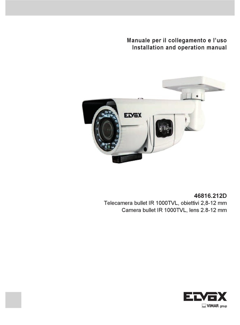
Elvox 46816.212D User manual

Elvox
Elvox 5VL4/660 User manual

Elvox
Elvox 559C User manual

Elvox
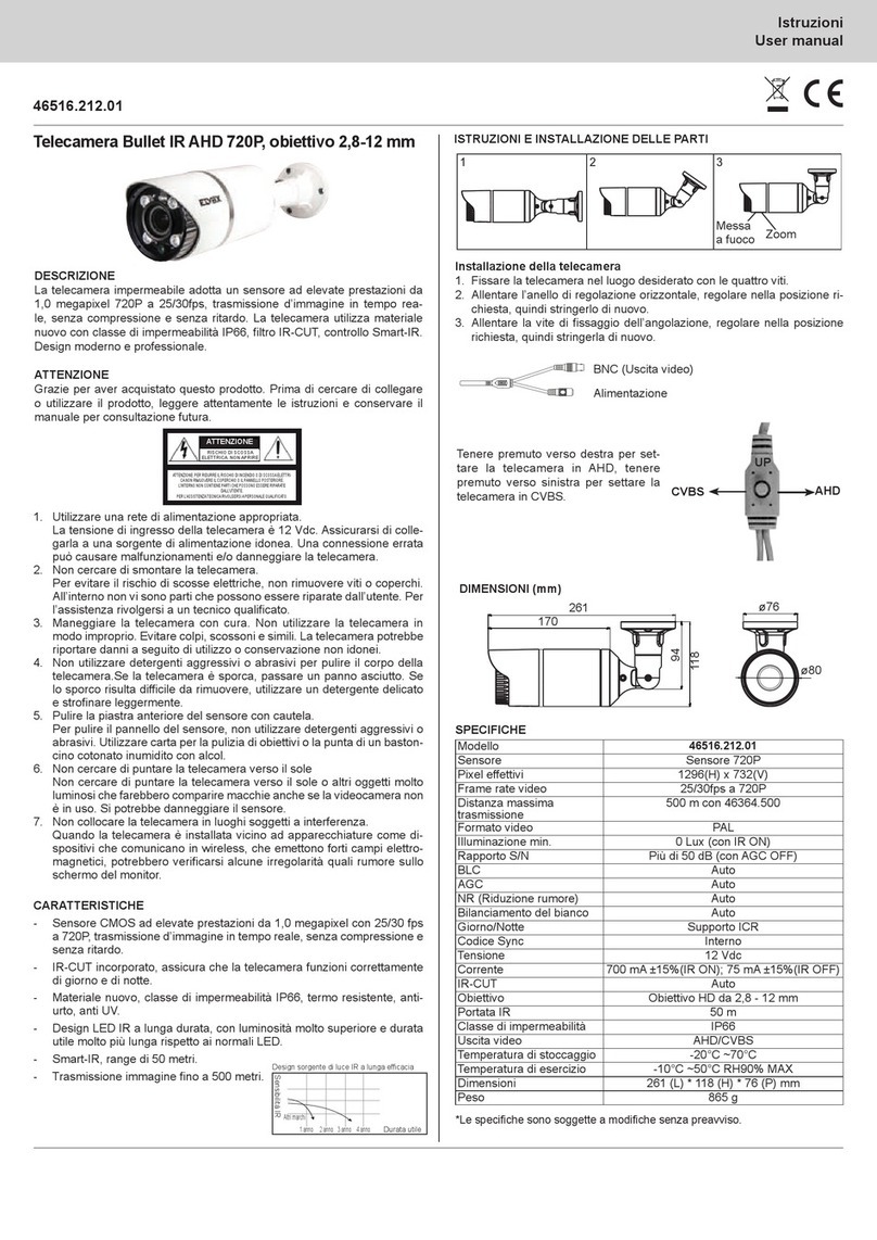
Elvox 46516.212B User manual

Elvox
Elvox 5VL0 User manual

Elvox
Elvox FW-V 3.00 User manual

Elvox
Elvox 46235.020 User manual

Elvox
Elvox 46816.212C User manual

Elvox
Elvox 46237.036 User manual

Elvox
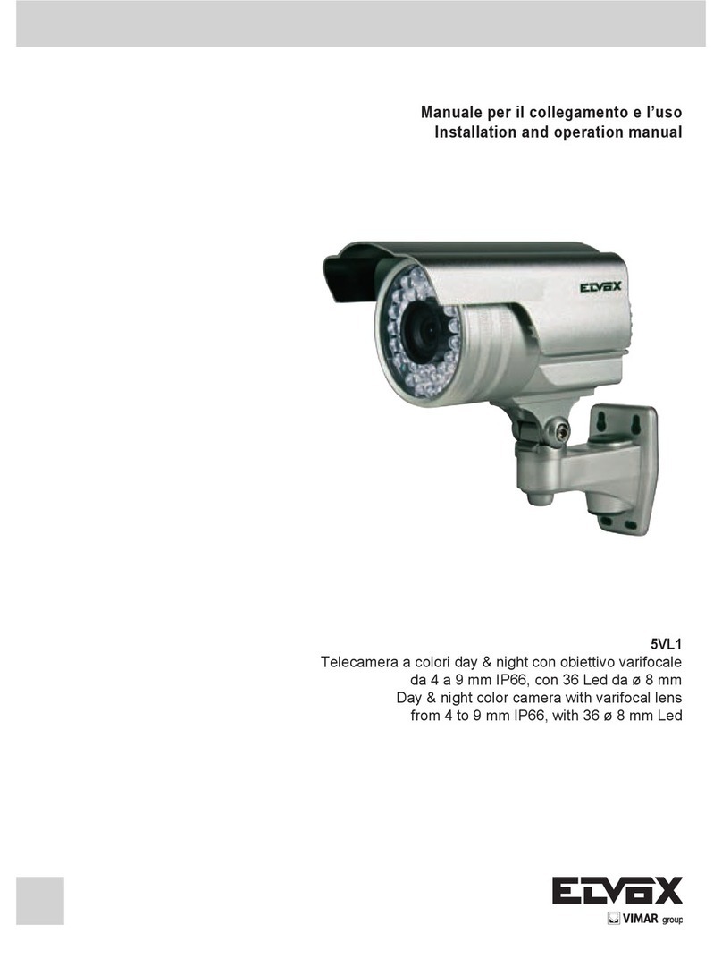
Elvox 5VL1 User manual