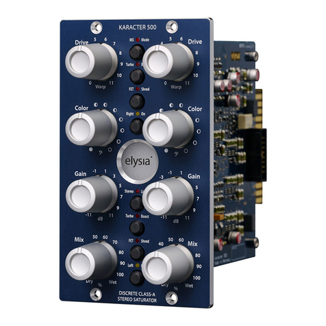
elysia Mpressor 500 User manual

mpressor 500

2
The compressor from the future
The mpressor 500 brings the heritage of our extremely pow-
erful rack mount mpressor into the 500 series format. Like its
bigger brother, the mpressor 500 combines serious punch
with a full and detailed class-A sound. Its great tone and ex-
ibility make it an excellent choice for recording and mixing,
while its remarkable special features take it far beyond the
borders of what normal compressors can do.
Extreme time constants, negative ratios, “antilog” release and
elysia’s innovative gain reduction limiter provide a whole
spectrum of unique dynamics shaping options. A new feature
of the 500 series module is its switchable THD boost allowing
on-the-y signal coloration and saturation eects capable of
delivering a grittier avor.
The elysia team wishes you great delight and compression de-
luxe with your new mpressor 500.
Compatibility ..............................................3
Installation ................................................3
Controls ...................................................4
Connectors ................................................6
Auto Fast ..................................................7
Anti Log ...................................................8
THD Boost .................................................9
Negative Ratios .......................................... 10
Gain Reduction Limiter................................... 11
Appendix................................................ 12
Deutsches Handbuch . . . 16 Manuel Français ... 30

3
Compatibility
The mpressor 500 is a module to be installed into an API 500
series compatible rack frame (not included). It needs the pow-
er supply and the audio connectors provided by this frame
and does not function stand alone.
The current consumption is 75 milliamperes at +/- 16 volts DC.
The mpressor 500 meets all mechanical and electronic speci-
cations of the VPR Alliance, providing the highest level of com-
patibility with common 500 series rack frames.
Installation
Just follow these easy steps to install your mpressor 500:
1. Switch your API 500 series compatible rack o and discon-
nect the power cable from mains.
2. Insert the module into a free slot of your rack. Make sure the
PCB connector matches with the rack connector.
3. Gently push the module in place - do not use any extensive
force here!
4. Tighten the front panel with two screws provided by your
rack manufacturer.
5. Connect your audio cables (see page 6 for more info) and
apply power to your rack.
And this is already it. Have lots of fun with your mpressor 500!

Release
25
15
10
2k5
2k0
700
21095
5
1k3
420
Thresh
4
9
13
-25
-23
-18
-6
15
-21
-14
Attack
10
5.0
1.5
180
160
90
2520
0.01
140
45
Ratio
2.0
1.6
1.4
-1.3
-1.0
-0.5
5.03.0
1.2
-0.8
9.0
GRL
15
20
25
0
1
4
810
30
2
6
Gain
4.0
2.0
0.5 22
14
108.0
0
ms
dB
ms
1:X
dB
dB
18
12
MPRESSOR
500
DISCRETE
CLASS-A
COMPRESSOR
4
Controls
Threshold (Thresh): The operating point of the compres-
sor. If the input level exceeds the value set with this controller,
the compression process will start.
Attack: The transient response of the compressor. It deter-
mines the time the mpressor 500 needs to reach 10 dB of gain
reduction.

5
Release: The return phase of the compressor. It controls
the period of time between the input signal falling below the
threshold and the mpressor 500’s return to unity gain.
Ratio: The relation between the input level and the output
level. As a specialty of the mpressor 500, even negative ratios
can be set here. (p. 10)
Gain Reduction Limiter (GRL): Restricts the control volt-
age. This innovative limiter is not placed in the audio path as
usual, but in the control circuit of the compressor. (p. 11)
Gain: The make-up gain of the mpressor 500. This control-
ler compensates for the loss in gain caused by the compres-
sion process.
Gain Reduction Meter: The display for the gain reduction
process. Shows the amount of compression measured in dB as
a visual support for the acoustic events.
GRL LED: indicates Gain Reduction Limiter activity. If this
LED is on, incoming signals will be held at the GR limit instead
of being compressed any further. (p. 11)
Auto Fast: A semi-automation. This function shortens the
attack time automatically on fast and loud signal impulses and
then returns to the value set with the controller. (p. 7)
Anti Log: This alternative characteristic of the release
curve follows an antilogarithmic course instead of the stan-
dard linear progress. (p. 8)
THD Boost: raises the level in front of the gain control ele-
ment, which generates additional harmonics and saturation
eects with a signicant inuence on the sonic structure. (p. 9)
Hit It! Activates the mpressor 500 (LED on) or deactivates
it with a hardwire bypass (GR meter remains active).

6
Connectors
Audio outputs (+4 dBu)
Pin assignment balanced: 1ground 2hot (+) 3ground
Pin assignment unbalanced: 1ground 2hot (+) 3idle
Audio inputs (+4 dBu)
Pin assignment balanced: 1ground 2hot (+) 3cold (-)
Pin assignment unbalanced: 1ground 2hot (+) 3ground

7
Auto Fast
The attack parameter is a crucial factor for the op-
eration of a compressor. Choosing the right time
setting is very important, but depending on the dy-
namic progress of the source material this is a dicult task –
no matter if single tracks or complete mixes are processed.
If a very short attack time is chosen, the compressor is able
to catch the short peaks, but on the other hand the sustain-
ing signal will also be processed, which might result in audible
distortion. Longer settings reduce distortion signicantly, but
then the compressor is too slow for catching fast impulses.
This is where the Auto Fast function comes into play. If you set
a longer attack and engage the Auto Fast mode, the attack
time will be shortened automatically on fast and loud signal
impulses. The compressor reduces the signal quickly and pre-
vents it from slipping through.
Then the attack time directly and automatically returns to its
original setting. In Auto Fast mode the compressor can be
very fast, but only when it is really needed.
Attack phase without Auto Fast Attack phase with Auto Fast
Time (s) Time (s)
Output level (dB) Output level (dB)

8
Anti Log
It is characteristic of a logarithmic release that the
time constant shortens when the amount of gain
reduction increases. The advantage of this behavior
is that short and loud peaks (e.g. drums) have a fast release
time, while the remaining material is processed with a slower
release time.
But if intentionally striking and creative compression is the
goal, it makes sense to turn things upside down. In the Anti
Log mode of the mpressor, the curve behaves just the other
way round: If the threshold value is passed and compression
starts, the release time will be longer at the beginning. If the
input signal starts to decline, however, the release time will
become faster as a result.
A special circuitry makes this behavior independent from the
absolute amount of gain reduction. No matter if the compres-
sor reduces 10, 15 or 20 dB, the curve will always stay the same
at the beginning and it will only become faster at the end.
With this feature you can create many exceptional compres-
sion eects just by the push of a button!
Release phase without Anti Log Release phase with Anti Log
Time (s) Time (s)
Output level (dB) Output level (dB)

9
THD Boost
Activating the THD Boost function raises the level in
front of the gain control element. This generates ad-
ditional harmonics inside the input stage of this am-
plier, which has a signicant inuence on the sonic structure
of a signal.
The mpressor 500 is a pure feed forward compressor, and the
gain potentiometer is placed before the control element. This
means that the intensity of the saturation can be raised or
lowered by dierent settings of the gain controller.
What’s special: The detector in the sidechain of the compres-
sor runs in parallel and is therefore not inuenced by the THD
Boost at all. The actual compression does not change, it is only
the sound which is being inuenced.
You generate a saturated signal which as a result is also re-
duced in dynamics, but the actual control of the compressor
itself is always based on the original dynamics including all
transients, impulses and so on.
THD Normal THD Boost
Input level (dB) Input level (dB)
THD+N (%) THD+N (%)

10
Negative Ratios
Negative ratios – what exactly does this mean? To
get a better understanding of this function, it makes
sense to realize what the ratio control of a ‘normal’
compressor does:
• 1:1 The signal remains linear, there is no compression pro-
cess going on.
• 1:2 After crossing the threshold, an increase of 2 dB at the
input will be compressed to an increase of 1 dB at the
output.
• 1:∞ After crossing the threshold, the output signal is con-
stantly held at the threshold level without reacting to
further increases at the input (limiter).
At a negative ratio, the characteristic curve bends and returns
back down after crossing the threshold. The louder the input
signal, the lower the output signal – perfect for groovy com-
pression eects.
To get a grip on the extreme ‘destruction’ this can cause, en-
gaging the Gain Reduction Limiter is just the right idea.
Standard compression ratio Negative compression ratio
Input Level (dB) Input Level (dB)
Output Level (dB) Output Level (dB)

11
Gain Reduction Limiter
A specialty of the mpressor 500 is the Gain Reduction
Limiter. This limiter is not placed in the audio path
where you might expect it, but in the control path of
the compressor instead.
When activated, it limits the control voltage according to the
setting of the GRL controller. This means: No matter how high
the input level might become – the total amount of gain re-
duction will never exceed the value you have set.
Just think about the GRL as a second threshold controller:
While the ‘regular’ threshold controller tells the compressor
when to start working, the GRL controller tells it when to com-
press no further.
Loud parts in an arrangement can keep their dynamics, as
they will not be compressed beyond the limit of the Gain Re-
duction Limiter.
Note: In order to avoid GRL activity, just turn its controller fully
counter-clockwise.
GRL compression progress GRL input to output ratio
Time (s) Input Level (dB)
Output Level (dB) Output Level (dB)
Attack phase
Release phase
GRL phase
GRL phase

12
Technical Details
Frequency response: <10 Hz - 390 kHz (-3 dB)
THD+N @ 0 dBu, 20 Hz - 22 kHz: 0.04 %
THD+N @ 10 dBu, 20 Hz - 22 kHz: 0.19 %
THD+N @ 0 dBu, 20 Hz - 22 kHz, THD Boost: 0.24 %
THD+N @ 10 dBu, 20 Hz - 22 kHz, THD Boost: 2.20 %
Noise oor, 20 Hz - 20 kHz (A-weighted): -79 dBu
Noise oor, 20 Hz - 20 kHz (A-weighted), THD Boost: -87 dBu
Dynamic range, 20 Hz - 22 kHz: 99 dB
Maximum input level: 21 dBu
Maximum output level: 22 dBu
Input/output impedance: 10 kOhm/68 Ohm
CE Conformity
The conformity of this device to the EU directives is
conrmed by the CE mark on the device.
This declaration becomes invalid by any unapproved modi-
cation of the device.
Nettetal, 01.10.2016 - Ruben Tilgner

13
Precautions
CAUTION: Electricity
• Make sure to operate your API 500 series compatible rack at
the specic mains voltage of your country.
• Replace rack frame fuse with the same type and value only.
• Your rack frame must be connected to ground.
• Do not use a damaged power cord.
• Never place containers with liquid on the rack.
• Do not expose this device to rain or moisture.
• Do not use this device near water.
• Refer service to qualied service sta only.
CAUTION: Temperature
• Surfaces of the device may become hot during operation.
• Do not install this device near any heat source such as radia-
tors, stoves or other heat sources.
CAUTION: Connecting & Mounting
• Never connect to the output of a power amplier.
• Do not apply extensive force when installing this device.
• Use the device according to this manual only.
CAUTION: Humidity
• If this device is moved from a cold place to a warm room,
condensation can occur inside the device. To avoid damag-
ing the unit please allow it to reach room temperature be-
fore switching it on.

14
Warranty Info
The mpressor 500 is covered by a limited warranty for a period
of 2 years against defects in parts and labor from the date of
purchase. Natural wear is not covered by this warranty. Re-
pairs or replacements will not extend the warranty period.
The warranty is given to the original purchaser only and is not
transferable. elysia will only give warranty on products pur-
chased through authorized elysia dealers. The warranty will
only be valid in the country of the original purchase unless
otherwise pre-authorized by elysia.
All warranties become void when the product has been dam-
aged by misuse, accident, neglect, modication, tampering or
unauthorized alteration by anyone other than elysia autho-
rized service personnel.
The warrantor assumes no liability for property damage or any
other incidental or consequential damage whatsoever which
may result from failure of this product. Any and all warrantees
of merchantability and tness implied by law are limited to
the duration of the expressed warranty.
elysia will not pay for express or overnight freight service or
pay for shipments to locations outside Germany. All damages
caused by transport are not covered by this warranty.
This warranty gives you specic legal rights and you may also
have other rights which vary from state to state. Some of the
above limitations may not apply to you.

15
Legal Info
The information in this document is subject to change with-
out further notice and shall not be deemed as an obligation
or warranty of any kind by the manufacturer. No warranties,
express or implied, are made with regard to the quality, suit-
ability or accuracy of this document.
The manufacturer reserves the right to change the contents
of this document and/or the associated products at any time
without the provision of prior notice. The manufacturer shall
not be held liable for damages of any kind arising from the
use, or the inability to use this product or its documentation.
The information in this document is subject to copyright. All
rights, technical changes and errata are reserved. No part of
this manual may be reproduced or transmitted in any form or
for any purpose without the explicitly written permission of
the copyright holders.
elysia and mpressor are registered trademarks of elysia GmbH.
Other product and brand names contained in this document
are used for identication purposes only. All registered trade-
marks, product designations or brand names used in this doc-
ument are the property of their respective owners.
The product has been manufactured in com-
pliance with the RoHS directive. The purpose
of this directive of the European Union is
the Restriction of Hazardous Substances (RoHS) in electronic
equipment in order to protect health and nature. Dispose
separately!
Version 1.1 © 2019 elysia GmbH

16
Der Kompressor aus der Zukunft
Der mpressor 500 trägt das Erbgut des fantastischen mpressor
rack ins 500er Modulformat. Wie sein großer Bruder vereint
der mpressor 500 enormen Punch mit einem vollen und de-
taillierten Class-A Sound. Seine herausragende Klanggüte und
Flexibilität machen ihn zur exzellenten Wahl beim Aufneh-
men und Abmischen, während seine vielen Sonderfeatures
erstaunliche Dynamik-Eekte weit außerhalb der Reichweite
normaler Kompressoren erzeugen.
Extreme Zeitkonstanten, negative Ratios, Antilog Release und
elysias innovativer Gain Reduction Limiter erönen ein kom-
plettes Spektrum an einzigartigen Möglichkeiten. Eine neue
Funktion des 500er-Moduls ist der THD Boost für Klangfär-
bung per Knopfdruck und Sättigungseekte, die den Kom-
pressor deutlich kantiger in Szene setzen.
Das elysia Team wünscht viel Freude und Kompression Deluxe
mit deinem neuen mpressor 500.
Kompatibilität ........................................... 17
Installation .............................................. 17
Bedienelemente ......................................... 18
Anschlüsse .............................................. 20
Auto Fast ................................................ 21
Anti Log ................................................. 22
THD Boost ............................................... 23
Negative Ratios .......................................... 24
Gain Reduction Limiter................................... 25
Anhang.................................................. 26
English Manual . . . 2 Manuel Français... 30

17
Kompatibilität
Das mpressor 500 Modul ist zur Installation in ein API 500 Se-
ries kompatibles Rack (nicht im Lieferumfang enthalten) vor-
gesehen. Es ist auf dessen Netzteil und Audioanschlüsse ange-
wiesen und funktioniert nicht‚stand alone‘.
Der Strombedarf beträgt 75 Milliampere bei +/- 16 Volt DC.
Der mpressor 500 erfüllt sämtliche mechanischen und elektro-
nischen Anforderungen der VPR Alliance, was eine größtmög-
liche Kompatibilität mit handelsüblichen Racks garantiert.
Installation
Die Installation des Moduls verläuft denkbar einfach:
1. Schalte dein API 500 Series kompatibles Rack aus und ent-
ferne das Netzkabel.
2. Stecke das Modul in einen freien Slot und richte die Kontak-
te der Platine genau auf die Steckleiste im Rack aus.
3. Drücke das Modul nun vorsichtig in die Steckleiste – dabei
bitte keine Gewalt anwenden!
4. Befestige die Frontplatte mit zwei Schrauben aus dem
Rackzubehör.
5. Verbinde die Audiokabel (mehr dazu auf Seite 20) und
schließe das Rack wieder an das Stromnetz an.
Und das war es auch schon. Wir wünschen viel Spaß mit dei-
nem mpressor 500!

Release
25
15
10
2k5
2k0
700
21095
5
1k3
420
Thresh
4
9
13
-25
-23
-18
-6
15
-21
-14
Attack
10
5.0
1.5
180
160
90
2520
0.01
140
45
Ratio
2.0
1.6
1.4
-1.3
-1.0
-0.5
5.03.0
1.2
-0.8
9.0
GRL
15
20
25
0
1
4
810
30
2
6
Gain
4.0
2.0
0.5 22
14
108.0
0
ms
dB
ms
1:X
dB
dB
18
12
MPRESSOR
500
DISCRETE
CLASS-A
COMPRESSOR
18
Bedienelemente
Threshold (Thresh): der Arbeitspunkt des Kompressors.
Überschreitet der Eingangspegel den hier eingestellten Wert,
setzt die Kompression ein.
Attack: das Einschwingverhalten des Kompressors. Be-
stimmt die Zeit, die der mpressor 500 benötigt, um 10 dB Gain
Reduction zu erzeugen.

19
Release: die Rücklaufzeit des Kompressors. Regelt die
Zeitspanne zwischen der Unterschreitung des Thresholds und
der Rückkehr auf den Nominalpegel.
Ratio: das Verhältnis von Eingangs- zu Ausgangspegel. Als
besondere Spezialität des mpressor 500 können auch negati-
ve Ratios eingestellt werden. (S. 24)
Gain Reduction Limiter (GRL): begrenzt die Steuerspan-
nung. Dieser neuartige Limiter liegt nicht etwa wie üblich im
Audiopfad, sondern im Regelweg des Kompressors. (S. 25)
Gain: Die Aufholverstärkung des mpressor 500 kompen-
siert den Pegel, der zuvor durch den Kompressions-Prozess
reduziert worden ist.
Gain Reduction Meter: die Anzeige der Pegel-Reduktion.
Als optische Unterstützung der akustischen Ereignisse wird
hier der Kompressionsverlauf in dB angezeigt.
GRL LED: zeigt die Aktivität des Gain Reduction Limiters
an. Leuchtet die LED, werden die Signale auf dem GR Limit ge-
halten und nicht noch stärker komprimiert. (S. 25)
Auto Fast: eine Halb-Automation. Durch diese Funktion
wird die Attack-Zeit bei schnellen und lauten Signalimpulsen
automatisch verkürzt. (S. 21)
Anti Log: Diese alternative Charakteristik der Release-
Kurve nimmt anstelle des linearen einen antilogarithmischen
Verlauf und klingt damit deutlich auälliger. (S. 22)
THD Boost: erhöht den Pegel vor dem Regelverstärker
und erzeugt somit zusätzliche Obertöne und Sättigungs-
Eekte, welche die Klangstruktur deutlich verändern. (S. 23)
Hit It! Aktiviert den mpressor 500 (LED an) oder schaltet
einen Hardwire-Bypass via Relais.

20
Anschlüsse
Audio-Ausgänge (+4 dBu)
Pinbelegung symmetrisch: 1Masse 2heiß (+) 3Masse
Pinbelegung unsymmetrisch: 1Masse 2heiß (+) 3frei
Audio-Eingänge (+4 dBu)
Pinbelegung symmetrisch: 1Masse 2heiß (+) 3kalt (-)
Pinbelegung unsymmetrisch: 1Masse 2heiß (+) 3Masse
Table of contents
Languages:
Other elysia Control Unit manuals
Popular Control Unit manuals by other brands
Telit Wireless Solutions
Telit Wireless Solutions LE910C1-NS Hardware Design Guide
TELECO AUTOMATION
TELECO AUTOMATION TVPLD868C80TT3 manual
M-system
M-system R7ML-EC16A instruction manual
GMI
GMI D5096S-106 instruction manual
Tibbo
Tibbo EM1000 Programmable Hardware Manual
Dell
Dell LC-EJ-10GE-10P installation guide
