Pololu Corporation A-Star 328PB User manual

Pololu A-Star 328PB User’s
Guide
1. Overview . . . . . . . . . . . . . . . . . . . . . . . . . . . . . . . . . . . . . . . . . . . . . . 2
2. Contacting Pololu . . . . . . . . . . . . . . . . . . . . . . . . . . . . . . . . . . . . . . . . . . 7
3. A-Star 328PB Micro pinout and components . . . . . . . . . . . . . . . . . . . . . . . . . . . . 8
4. Getting Started . . . . . . . . . . . . . . . . . . . . . . . . . . . . . . . . . . . . . . . . . . 12
4.1. Connecting power . . . . . . . . . . . . . . . . . . . . . . . . . . . . . . . . . . . . . 12
4.2. Connecting to the serial interface . . . . . . . . . . . . . . . . . . . . . . . . . . . . . 12
4.3. Programming using the Arduino IDE . . . . . . . . . . . . . . . . . . . . . . . . . . . 14
4.4. ATmega328PB support in the Arduino IDE . . . . . . . . . . . . . . . . . . . . . . . . 22
5. The A-Star 328PB Serial Bootloader . . . . . . . . . . . . . . . . . . . . . . . . . . . . . . . 24
Pololu A-Star 328PB User’s Guide © 2001–2018 Pololu Corporation
https://www.pololu.com/docs/0 74/all Page 1 of 25

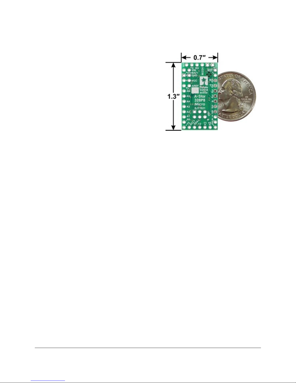
A-Star 328PB Micro, bottom view with
dimensions.
1. Overview
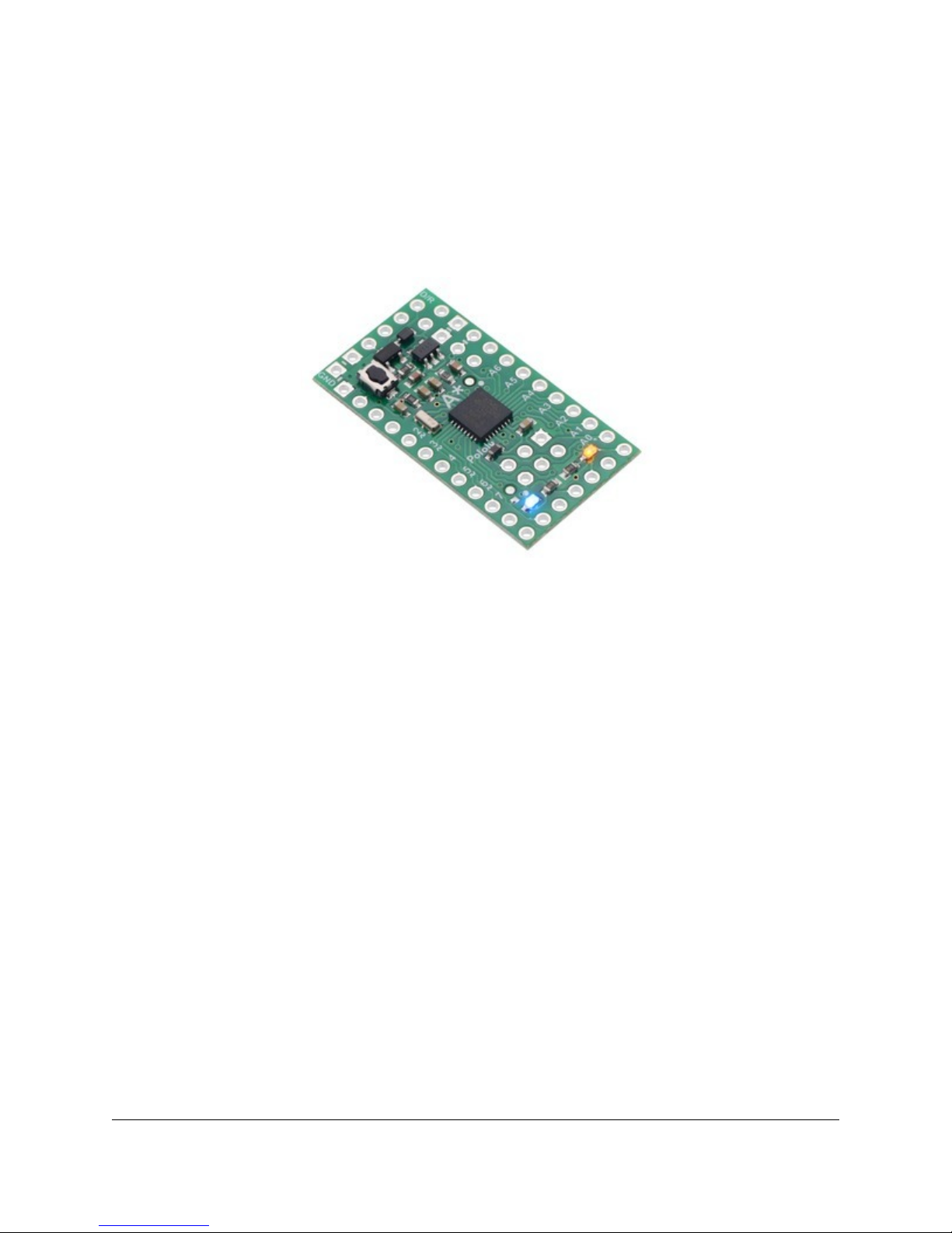
The Pololu A-Star 328PB Micro is a general-purpose
programmable module based on the ATmega328PB AVR
microcontroller, which has 32 KB of flash program
memory and 2 KB of RAM. The ATmega328PB is a
backward-compatible, improved replacement for the
popular ATmega328P found on other programmable
modules like our Baby Orangutan B-328
[https://www.pololu.com/product/1220] and the Arduino Uno
[https://www.pololu.com/product/2191] and Pro Mini, so
programs written for those other boards will generally
work on the A-Star 328PB Micro with appropriate
adjustments for any differences in clock speed. On-board
features of the A-Star (abbreviated A*) include a
resonator, user and power LEDs, and a reset button. The
board includes a low-dropout linear voltage regulator that allows it to be powered from external
supplies up to 15 V, and reverse voltage protection on this main power input helps safeguard against
accidental damage. The board can also be powered through its TTL serial header by a USB-to-serial
adapter, and an integrated power switching circuit makes it safe to have both supplies connected at
the same time.
The A-Star 328PB Micro breaks out 19 general-purpose I/O lines along two rows of pins, including
seven usable as PWM outputs and eight usable as analog inputs; another five GPIO pins (including
two usable as PWM outputs) can be accessed along the bottom edge of the board. It provides both
an in-system programming (ISP) header and a connector for TTL serial programming along the top
edge. The board fits all this into a 1.3″ × 0.7″ area (the same size as the Arduino Pro Mini), and
its 0.1″ pin spacing makes the A* easy to use with solderless breadboards [https://www.pololu.com/
category/28/solderless-breadboards], perfboards, and 0.1″-pitch connectors [https://www.pololu.com/category/
19/connectors].
The A-Star 328PB Micro is available in four logic voltage and resonator frequency combinations:
•5 V, 16 MHz [https://www.pololu.com/product/3160] (blue power LED)
•5 V, 20 MHz [https://www.pololu.com/product/3161] (red power LED) Note: See speed warning
below.
•3.3 V, 8 MHz [https://www.pololu.com/product/3162] (green power LED)
•3.3 V, 12 MHz [https://www.pololu.com/product/3163] (yellow power LED)
Each of the four versions uses a different power LED color as a way to differentiate them.
Pololu A-Star 328PB User’s Guide © 2001–2018 Pololu Corporation
1. Overview Page 2 of 25

Speed warning for 20 MHz version: The 20 MHz resonator frequency exceeds the
maximum explicitly allowed in the ATmega328PB datasheet. In our basic testing, the 20
MHz resonator appears to function without problems, but for any critical applications you
should confirm for yourself that this product is appropriate.
Either a USB-to-serial adapter or an AVR in-system programmer (ISP) is required to
program the A-Star 328PB Micro from a computer. We recommend our USB AVR
Programmer v2.1 [https://www.pololu.com/product/3172], which can be used as both, and
can be configured to run at either 3.3 V or 5 V.
Features
• Dimensions: 1.3″ × 0.7″
• Programmable ATmega328PB AVR microcontroller
◦ 32 KB flash (0.5 KB used by bootloader, leaving 31.5 KB available for user program
by default)
◦ 2 KB SRAM
◦ 1 KB EEPROM
• All I/O lines from the ATmega328PB broken out in a compact package
◦ 19 general-purpose I/O pins available along the sides of the board
◦ 5 additional I/O pins available on bottom edge
◦ 9 pins can be configured as hardware PWM outputs (7 along sides of board)
◦ 8 pins can be configured as analog inputs
• Preloaded with Arduino-compatible TTL serial bootloader
• 6-pin TTL serial programming header for use with a USB-to-serial adapter (we recommend
our USB AVR Programmer v2.1 [https://www.pololu.com/product/3172], which can act as a USB-
to-serial adapter)
• 6-pin ISP header for use with an external AVR programmer (we recommend our USB AVR
Programmer v2.1 [https://www.pololu.com/product/3172])
• Power LED and user-controllable LED
• Reset button
• Two power options:
Pololu A-Star 328PB User’s Guide © 2001–2018 Pololu Corporation
1. Overview Page 3 of 25

◦ 3.8 V to 15 V (3.3 V versions) or 5.5 V to 15 V (5 V versions) on BAT+
◦ USB-to-serial adapter can supply power to VCCIN on the serial header
• Reverse-voltage protection on BAT+ supply
Differences between the ATmega328P and ATmega328PB
Compared to the ATmega328P (and ATmega328), the ATmega328PB microcontroller offers a number
of improvements, including:
• Two additional GPIO pins: PE0 and PE1
• Two pins that were previously analog inputs only (ADC6 and ADC7) can now also be used
as digital inputs and outputs: PE2 and PE3
• Two additional 16-bit Timer/Counters: TC3 and TC4 (for a total of two 8-bit timers and three
16-bit timers)
• Three additional PWM output pins
• A second USART (TTL serial port)
• A second TWI (Two-Wire Serial Interface, I²C-compatible)
• A second SPI (Serial Peripheral Interface)
• A peripheral touch controller (PTC) for adding capacitive touch buttons, sliders, and wheels
The ATmega328PB is code-compatible with the ATmega328P, meaning code compiled for an
ATmega328P will run as intended on an ATmega328PB. This application note [https://www.pololu.com/
file/0J1464/Atmel-42559-Differences-between-ATmega328P-and-ATmega328PB_ApplicationNote_AT15007.pdf] (283k
pdf) by Atmel (now part of Microchip) comprehensively describes the differences between the
ATmega328PB and its predecessors.
Our Arduino software add-on makes it easy to use the additional GPIO functionality, PWM outputs,
and TTL serial port. The other new features of the ATmega328PB can still be used from the Arduino
environment through direct register access or custom libraries.
The A-Star family
Pololu A-Star 328PB User’s Guide © 2001–2018 Pololu Corporation
1. Overview Page 4 of 25

From top to bottom: A-Star 328PB Micro,
32U4 Micro, 32U4 Mini SV, and 32U4
Prime SV.
The A-Star 328PB Micro is a part of our larger A-Star
family [https://www.pololu.com/category/149/a-star-
programmable-controllers], all of whose members are
based on AVR microcontrollers and are preloaded with
Arduino-compatible bootloaders. The table below
shows some key features and specifications of our A-
Star microcontroller boards to help you choose the
right one for your application.
Pololu A-Star 328PB User’s Guide © 2001–2018 Pololu Corporation
1. Overview Page 5 of 25

A-Star 328PB
Micro
A-Star 32U4
Micro
A-Star 32U4 Mini
ULV
A-Star 32U4 Mini
LV
A-Star 32U4 Mini
SV
A-Star 32U4
Prime LV
A-Star 32U4
Prime SV
A-Star 32U4 Robot
Controller LV
A-Star 32U4 Robot
Controller SV
Microcontroller: ATmega328PB ATmega32U4
User I/O lines: 24 18 26 26(1) 26(1)
PWM outputs: 9 7 7 7 7(1)
Analog inputs: 8 8 12 12 12(1)
Ground access
points: 6 2 4 43 44
User LEDs: 1 2 3 3 3
User
pushbuttons: — — — 3 3
USB interface:
Reset button:
Power switch:
Buzzer option:
microSD option:
LCD option:
Motor drivers:
Operating
voltage:
3.3V VCC: 3.8 V to
15 V
5V VCC: 5.5 V to
15 V
5.5 V to 15 V
ULV: 0.5 V to
5.5 V
LV: 2.7 V to 11.8 V
SV: 5 V to 40 V
LV: 2.7 V to 11.8 V
SV: 5 V to 36 V
LV: 2.7 V to 11 V
SV: 5.5 V to 36 V
Regulator type: 3.3 V or 5 V l near 5 V l near
5 V sw tch ng
ULV: step-up
LV: step-up/step-
down
SV: step-down
5 V sw tch ng
LV: step-up/step-
down
SV: step-down
5 V sw tch ng
LV: step-up/step-down
SV: step-down
Regulated
current:(2) 100 mA 100 mA
ULV: 500 mA
LV: 1 A
SV: 800 mA
1 A LV: 1 A
SV: 1.5 A
Dimensions: 1.3″ × 0.7″ 1″ × 0.6″ 1.9″ × 0.7″ 2.8″ × 2.1″ 2.6″ × 2.2″
Weight: 1.5 g(3) 1.3 g(3) 3.4 g(3) 13 g to 33 g 14 g to 23 g
1Some m crocontroller resources are used by on-board hardware.
2These values are rough approx mat ons for compar son purposes. Ava lable current depends on nput voltage, current consumed
by the board, amb ent cond t ons, and regulator topology. See product documentat on and performance graphs for deta ls.
3W thout ncluded opt onal headers.
Pololu A-Star 328PB User’s Guide © 2001–2018 Pololu Corporation
1. Overview Page 6 of 25

2. Contacting Pololu
We would be delighted to hear from you about any of your projects and about your experience with
the A-Star 328PB. You can contact us [https://www.pololu.com/contact] directly or post on our forum
[https://forum.pololu.com/]. Tell us what we did well, what we could improve, what you would like to see
in the future, or anything else you would like to say!
Pololu A-Star 328PB User’s Guide © 2001–2018 Pololu Corporation
2. Contacting Pololu Page 7 of 25

3. A-Star 328PB Micro pinout and components
These files document the hardware design of the A-Star 328PB Micro:
•Pinout diagram [https://www.pololu.com/file/0J1465/a-star_328pb_micro_pinout.pdf] (579k pdf)
•Schematic diagram [https://www.pololu.com/file/0J1463/a-star-328pb-micro-schematic.pdf] (132k
pdf)
•Dimension diagram [https://www.pololu.com/file/0J1461/a-star-328pb-micro-dimensions.pdf] (199k
pdf)
•3D model [https://www.pololu.com/file/0J1462/a-star-328pb-micro.step] (5MB step)
•Drill guide [https://www.pololu.com/file/0J1460/ac05a-drill.dxf] (50k dxf)
The pinout diagram identifies the I/O and power pins on the A-Star 328PB Micro, and is shown below.
The A-Star 328PB is based on the ATmega328PB AVR microcontroller from Atmel (now part of
Microchip), and most pins on the board are directly connected to the microcontroller. The A* circuit
board has printed indicators that you can use to quickly identify each pin’s capabilities: pins labeled
with A0 through A7 can be used as an analog input, and a square wave symbol under the pin number
means it can be used as a PWM output. All of the pins are labeled on the bottom silkscreen, and
some of the pins are also labeled on the top silkscreen (as space allows). For more information about
each pin’s capabilities, see Microchip’s ATmega328PB documentation [https://www.microchip.com/
wwwproducts/en/ATmega328PB].
Pololu A-Star 328PB User’s Guide © 2001–2018 Pololu Corporation
3. A-Star 328PB Micro pinout and components Page 8 of 25

Note that the pins labeled SDA1 (PE0) and SCL1 (PE1) are not limited to being used for TWI/
I²C and can be used as general-purpose I/O pins. These pins are new on the ATmega328PB and
have no equivalent on the ATmega328P, so they do not yet have official pin numbers in the Arduino
environment; therefore, we recommend using the constants SDA1 and SCL1 instead of the pin
numbers 22 and 23 in Arduino code. (See Section 4.4 for more information on ATmega328PB support
in the Arduino IDE.)
LEDs
The A-Star 328PB has two indicator LEDs:
• A yellow user LED in the lower right is connected to Arduino digital pin 13, or PB5. You can
drive this pin high in a user program to turn this LED on.
• A power LED in the lower left indicates when the logic supply voltage, VCC, is present. The
color of the power LED depends on the version of the board:
VCC Frequency Power LED color
5 V 16 MHz Blue
5 V 20 MHz Red
3.3 V 8 MHz Green
3.3 V 12 MHz Yellow
Connectors
The A-Star 328PB includes a 6-pin header along its top edge that can be used for TTL serial
programming with the preloaded Arduino-compatible bootloader. The serial interface is compatible
with our USB AVR Programmer v2.1 [https://www.pololu.com/product/3172] and commonly available
USB-to-serial adapter cables (e.g. FTDI cables). See Section 4.2 for more information about the serial
Pololu A-Star 328PB User’s Guide © 2001–2018 Pololu Corporation
3. A-Star 328PB Micro pinout and components Page 9 of 25

interface. The TTL serial header can also provide power to the A-Star through the VCCIN pin, as
detailed below.
The board also has a 6-pin ISP header that allows it to be programmed with an external AVR in-system
programmer, such as our USB AVR programmer v2.1 [https://www.pololu.com/product/3172]. Pin 1 of the
header is indicated with a small dot and has an octagonal shape.
A-Star 328PB Micro with included
header pins soldered for breadboard
use.
A-Star 328PB Micro connected to the
serial pins of a Pololu USB AVR
Programmer v2.1.
Power
The main power input for the A-Star 328PB Micro is the BAT+ pin, which is reverse-protected and can
accept power sources up to 15 V. Reverse-protected power can be supplied to other devices by using
the VIN pin as an output. The VIN voltage feeds into a 100 mA low-dropout (LDO) regulator to provide
a regulated 3.3 V or 5 V logic supply called VCC. Alternatively, the external supply can be connected
directly between VIN and GND, bypassing the reverse-voltage protection.
The VCCIN pin on the A-Star 328PB Micro serial header functions as a secondary power input for
VCC that bypasses the regulator. To avoid unexpected behavior, it is important for the VCCIN voltage
Pololu A-Star 328PB User’s Guide © 2001–2018 Pololu Corporation
3. A-Star 328PB Micro pinout and components Page 10 of 25

to match the regulator voltage on the version you are using. (Supplying a higher voltage to VCCIN
raises the logic voltage of your system, and supplying a lower voltage can result in a brownout reset
and/or violate the maximum frequency vs. VCC specifications in the ATmega328PB datasheet.)
The A* board includes a switching circuit that makes it safe to have power supplies connected to both
VCCIN and BAT+ at the same time, but we do not recommend connecting multiple power sources
when the board is powered through VIN instead of BAT+, as the switching circuit does not prevent
current from flowing into or out of VCCIN in that situation.
Pololu A-Star 328PB User’s Guide © 2001–2018 Pololu Corporation
3. A-Star 328PB Micro pinout and components Page 11 of 25

4. Getting Started
4.1. Connecting power
Before you can program the A-Star 328PB, you need to connect power to it.
See Section 3 for information about what kind of power supply you can use and which pins to connect
it to.
After you connect power for the first time, you should see the A-Star’s power LED turn on. If you do not
see the A-Star 328PB’s power LED turn on when you connect power, double check your connections,
make sure your power supply is turned on and working, and make sure any headers pins you are
using are soldered.
You should also see the yellow user LED blinking once every two seconds. The default program that
we ship on the A-Star 328PB blinks the LED, but this program will be erased when you program the
board for the first time, so if your board has been programmed before then you might not see the LED
blinking.
After connecting power, it is good to press the board’s reset button to make sure the serial bootloader
is working. When you press the reset button, the A-Star 328PB serial bootloader will blink the user LED
very quickly three times, wait for one second, and then exit. If you see this triple blink after pressing
the reset button, it means the bootloader is present on the device and it can run. If there is no triple
blink after you push the reset button, then there might be a problem with your power supply or the
bootloader might have been erased.
4.2. Connecting to the serial interface
The A-Star 328PB has a TTL serial interface that allows you to upload programs using the serial
bootloader and to send and receive serial data. The serial interface consists of the following six pins:
1. GND
2. GND, usually connected to CTS on a serial adapter to drive it low
3. VCCIN – alternative power input
4. TX – TTL serial data output
5. RX – TTL serial data input
6. D/R – DTR/RTS, used by the serial adapter to trigger a reset
This serial interface is compatible with our USB AVR Programmer v2.1 [https://www.pololu.com/product/
3172] and commonly available USB-to-serial adapter cables (e.g. FTDI cables). We recommend using
the Pololu USB AVR Programmer v2.1 because it can be configured to operate at either 3.3 V or 5 V,
Pololu A-Star 328PB User’s Guide © 2001–2018 Pololu Corporation
4. Getting Started Page 12 of 25

and it can program the A* over the ISP interface as well as the serial interface.
The TX and RX lines are directly connected to the ATmega328PB microcontroller, without any level
shifting. To avoid issues due to mismatched voltages, it is best to use a USB-to-serial adapter that
operates at the same voltage as the A-Star 328PB board you want to program. The Pololu USB AVR
Programmer v2.1 can be configured to operate at either 3.3 V or 5 V, so it is suitable for both 3.3 V
and 5 V A-Stars.
The VCCIN pin is an alternative power input that you can use to power the A-Star 328PB. Many USB-
to-serial adapter cables provide power on this pin, and the Pololu USB AVR Programmer v2.1 can
be configured to optionally provide either 3.3 V or 5 V power on this pin. The A* board includes a
switching circuit that makes it safe to have both VCCIN and BAT+ power supplies connected at the
same time. If power is supplied to VCCIN, It is important for the voltage to match the regulator voltage
on your board, as detailed under the “Power” heading in Section 3.
The D/R pin is used to reset the ATmega328PB. It should be connected to the DTR or RTS control
signal from the serial adapter, and a falling edge (which occurs when the control signal is asserted) will
cause the A-Star’s microcontroller to reset. This feature, called “auto reset”, is often used by Arduino-
compatible boards to automatically reset the microcontroller into bootloader mode before a program is
serially uploaded to it. If your A-Star is running at 5 V while your serial adapter is running at 3.3 V, the
auto reset feature will not work, so we recommend using a serial adapter that operates at the same
voltage as the A-Star.
To connect a USB AVR Programmer v2.1 to the A-Star 328PB’s serial interface so that you can upload
programs or send and receive serial data, follow these instructions:
1. Open the Pololu USB AVR Programmer v2 Configuration Utility software. Set the “Regulator
mode” to match the operating voltage of your A-Star. Make sure that the “Line A function”
and “Line B functions” settings are set to their default values, which are “(none)” and “DTR”
respectively.
2. Record the name of the “TTL port” shown in the software. You will need this later when
configuring the Arduino IDE or other software to talk to the A-Star.
3. Connect the programmer’s 6-pin serial interface to the A-Star 328PB’s 6-pin serial interface.
If you have soldered male header pins into the A-Star, you can simply plug it into the
programmer’s 6-pin female header, with D/R connecting to the programmer’s B pin.
Pololu A-Star 328PB User’s Guide © 2001–2018 Pololu Corporation
4. Getting Started Page 13 of 25

Programming the A-Star 328PB from the
Arduino IDE.
A-Star 328PB Micro connected to the serial pins of a Pololu USB AVR Programmer
v2.1.
4.3. Programming using the Arduino IDE
The A-Star 328PB ships with a preloaded Arduino-
compatible TTL serial bootloader (which uses 0.5 KB of
flash memory, leaving 31.5 KB available for the user
program). We provide a software add-on that enables
you to program the board from the Arduino integrated
development environment (IDE). The Arduino IDE is a
cross-platform, open source application that integrates a
C++ code editor, the GNU C++ compiler, and a program
upload utility.
These instructions assume that you have already
powered your A-Star 328PB (see Section 4.1) and
connected its serial interface to your computer using a
serial adapter (see Section 4.2).
Pololu A-Star 328PB User’s Guide © 2001–2018 Pololu Corporation
4. Getting Started Page 14 of 25

1. Download the Arduino IDE from the Arduino Download page [http://arduino.cc/en/Main/
Software], install it, and start it. These steps were tested with the Arduino IDE 1.8.5, so we
recommend using version 1.8.5 or later.
2. In the Arduino IDE, open the File menu (Windows/Linux) or the Arduino menu (macOS) and
select “Preferences”.
3. In the Preferences dialog, find the “Additional Boards Manager URLs” text box (highlighted in
the picture below). Copy and paste the following URL into this box:
https://files.pololu.com/arduino/package_pololu_index.json
If there are already other URLs in the box, you can either add this one separated by a comma
or click the button next to the box to open an input dialog where you can add the URL on a
new line.
Pololu A-Star 328PB User’s Guide © 2001–2018 Pololu Corporation
4. Getting Started Page 15 of 25

Adding a Boards Manager index for Pololu boards in the Arduino IDE’s Preferences dialog.
4. Click the “OK” button to close the Preferences dialog.
5. In the Tools > Board menu, select “Boards Manager…” (at the top of the menu).
6. In the Boards Manager dialog, search for “Pololu A-Star Controllers”.
7. Select the “Pololu A-Star Controllers” entry in the list, and click the “Install” button.
8. After the installation finishes, click the “Close” button to close the Boards Manager dialog.
9. In the Tools > Board menu, select the “Pololu A-Star 328PB” entry. If you do not see the A-
Star entries in the Board menu, try scrolling the menu with the arrows at the top and bottom,
and try restarting the Arduino IDE.
Pololu A-Star 328PB User’s Guide © 2001–2018 Pololu Corporation
4. Getting Started Page 16 of 25

Selecting the Pololu A-Star 328PB in the Boards menu.
10. After you select the A-Star 328PB, the Tools > Version menu should appear. In this menu,
select the entry that corresponds to your board.
Pololu A-Star 328PB User’s Guide © 2001–2018 Pololu Corporation
4. Getting Started Page 17 of 25

Selecting the right version of the A-Star 328PB in the Version menu.
11. In the Tools > Port menu, select the port for your serial adapter. If you are using the Pololu
USB AVR Programmer v2, you should select its TTL port.
12. Open up the “Blink” Arduino example, which can be found under File > Examples >
01.Basics > Blink. The code in this example will blink the yellow LED. When you select the
Blink example, a new Arduino IDE window will open up. It is OK to close the first window.
Pololu A-Star 328PB User’s Guide © 2001–2018 Pololu Corporation
4. Getting Started Page 18 of 25

Selecting the Blink example in the Arduino IDE.
13. Press the “Upload” button to compile the sketch and upload it to the device. If everything goes
correctly, you will see the message “Done uploading” appear near the bottom of the window.
If you see an error message, refer to the “Upload Troubleshooting” section below.
Pololu A-Star 328PB User’s Guide © 2001–2018 Pololu Corporation
4. Getting Started Page 19 of 25

Uploading a sketch to the A-Star using the Arduino IDE.
14. If you uploaded the Blink sketch, then the yellow LED should be blinking once every two
seconds. However, we ship the A-Star 328PB with that same example already programmed
onto it, so you might not be convinced that anything has changed. Try changing the delay
values in the sketch to something else and uploading again to see if you can change the
speed of the LED.
After you succeed in programming your device from the Arduino IDE, there are many resources you
can use to learn more:
• See Section 4.4 for information about ATmega328PB support in the Arduino IDE.
• The Arduino IDE has many examples [http://arduino.cc/en/Tutorial/HomePage] that can run on A-
Stars.
• The Arduino website has a Language Reference [http://arduino.cc/en/Reference/HomePage], a
wiki called the The Arduino Playground [http://playground.arduino.cc/], and other resources.
• The ATmega328PB is very similar to the ATmega328P used on boards like the Arduino Uno
Pololu A-Star 328PB User’s Guide © 2001–2018 Pololu Corporation
4. Getting Started Page 20 of 25
Table of contents