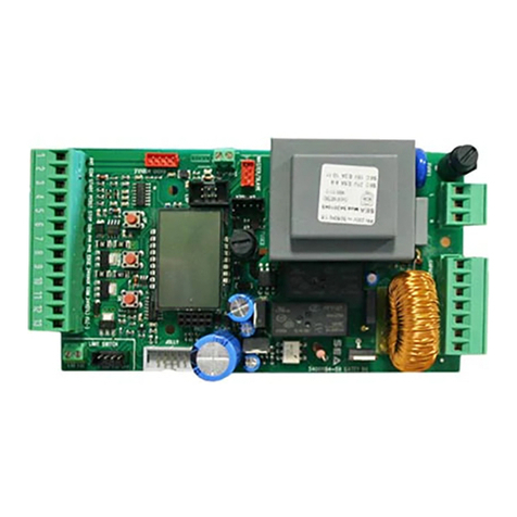
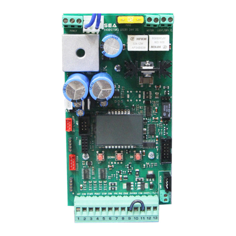
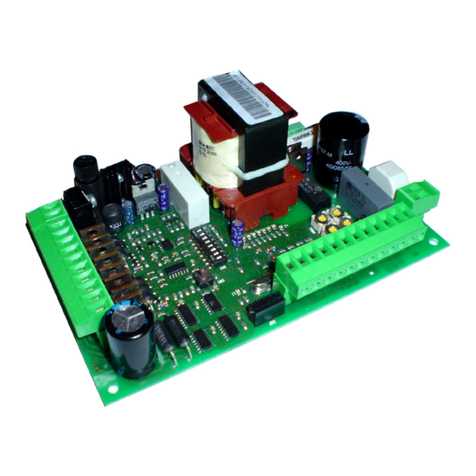
SEA GATE 1 DG R2BF User manual

112 RE. 1 /22
taliano
nlis
ranais
spaol
taliano
International registered trademark n. 804888
SEA S.p.A.
ona ndstriale Sant Atto 2 Teramo TA
Telephone 1 1 Fa 1
.seateam.com
seacomseateam.com
GATE 1 DG R2BF
ETRAE D MAD ER AE SRRE BATTET BARRERE E RTE DA GARAGE
TR T FR SDG GATES SG GATES BARRERS AD GARAGE DRS
ARMRE DE MMADE R RTAS SSATS BATTATS BARRERES ET RTES DE GARAGE
ETRA EETRA ARA AEAS RREDAS ABATBES BARRERAS ERTAS BASATES

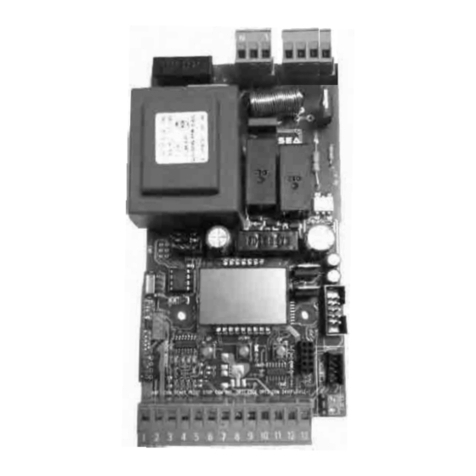
COMPONENTI - COMPONENTS
1 mm
mm
International registered trademark n. 804888
--------
--------
--------
--------
-
-
DSA
1
1 1 1 1 1 1 2
2
11 1
12
11
R1
F1
T1
R2
A SS
E
D
MS
TR1
2
F2
ITALIANO ENGLISH
ingresso / uscita
motore - condensatore
luce cortesia
alimentaione
24V~
encoder
finecorsa precablato
finecorsa non
precablato
ricevente RX
ricevente FIX
programmaione
modulo esterno
master / slave
JOLLY 3
SEACLOUD
triac pilotaggio motore
relay motore
e luce cortesia
relay scambio motore
Fusibile 6.3AT su 230V
10AT su 115V
1A fusibile accessori
trasformatore
alimentaione
1
2
A
S
E
MS
T1
R1
R2
F1
F2
TR1
input output
motor capacitor
coutesy light
power supply
24V~
encoder
pre-wired limit-switch
not pre-wired limit-
switch
RX receiver
RF FIX receiver
programming
external module
master / slave
JOLLY 3
SEACLOUD
motor control triac
motor and
courtesy light relay
motor exchange relay
Fuse 6.3AT on 230V
10AT on 115V
1A accessories fuse
power transformer
DATI TECNICI - TECHNICAL DATA
ALIMENTAZIONE 2 ac / z
11ac / z
TEMPERATURA DI ESERCIZIO 2
POWER SUPPLY WORKING TEMPERATURE
ASSORBIMENTO IN STAND-BY mA SCATOLA PER ESTERNO 1 2 12 mm
STAND-BY ABSORPTION EXTERNAL BOX

Partial opening Start
Photocell 2
Safety Edge
Common
Common
Photocell 1
1 - CONNECTIONS
taliano
EGS
International registered trademark n. 804888
3 - JUMPERS
OPTIONAL
Start
Stop
Antenna
Flashing lamp (-)
AUX
* (24V 500 mA max)
* 24V 500 mA max
(Accessories)
Opening Limit Switch (green)
Closing Limit Switch (yellow)
Common (white)
* 24V (red)
Common
Opening Limit Switch (green)
Closing Limit Switch (yellow)
The maimm indicated load of mA refers to the maimm load distrited
on all 2 otpts inclded the asorption of the receier on oard mA
n the 2 A otpt it is possile to connect a maimm load of mA
ARG The control nit is desined
for the atomatic detection of not sed
.. inpts hotocells Stop and imit
sitch ecept for the SAFET EDGE
inpt. The eclded inpts drin the
selfprorammin can e restored
throh the T STATS E
men chapter 1 ithot need to repeat
the control nit prorammin
TE
The herein reported fnctions are aailale startin from Softare Reision .2 of this
control nit and it is compatile ith prorammer
2 - JUMPERS
1
2
11 1
12
11
2ac
Ma. 1 mA
1
1
2
11 1
12
11
1 1 1 1 1 1 2
2
M
EDER
ANT COM START PEDST STOP COM PH1 PH2 EDGE 24VAUX COM 24V(FL) (FL)-
Courtesy light (phase)
LIGHT LIGHTN MCL MN MOP CAPACITOR
Courtesy light (neutral)
Closing Motor 1
Neutral Motor 1
Opening Motor 1
Motor 1 capacitor
A
RAD MDE
ETR
RGRAMMG
BTTS
UP DOWN OK
ETERA MDE
ETR
E
S
E RGRAMMER
irmare pdate
/SEAD
ETR
Neutral
Line
green or black
white or blue
brown or red
1
Partial opening Start
Photocell 2
Safety Edge
Common
Common
Photocell 1
Start
Stop
Antenna
Flashing lamp (-)
AUX
* (24V 500 mA max)
* 24V 500 mA max
(Accessories)
Common
CCT DC T TCD CT T

3 - CONNECTIONS ON CN1
Common
Common
Photocell 1
Common
Photocell 2
Partial Opening START
taliano
EGS
International registered trademark n. 804888
TX1
TX2
24V
1
1
12
11
1
1
2
1
Start
Stop
Antenna
RX1
RX2
.1 START ..
n clamps 2 and
The automation can be opened or closed through an impulse
transmitted to this input (via e button, eboard, etc.). To
connect other Start devices (for ex. the magnetic loop) refer to
the respective instructions
ote 1 For details on the logics that can be associated to the
START button, see chapter 1 GS
ote 2 If this contact is engaged during the pause (eg. Timer),
the gate will not close until releasing
.2 ARTA EG START ..
n clamps 2 and
The input allows to obtain the partial opening. It is possible to
manage the opening space through the men or through
the OLLY 3. It is also possible to manage the partial opening
pause time through the men 1
ote 1 For details on the logics that can be associated to the
PARTIAL OPENIN START button, see chapter 1 GS
ote 2: If this contact is engaged during the pause (eg. Timer),
the gate will not close until releasing
. ST .. n clamps and
If this button is pressed the engine stops immediatel in whatever condition or position it is. A new Start
command will be required to restore the movement.
ote After the Stop command, the engine will always re-start in closing
. TE 1 AD TE 2
ma m clamp CM clamps
otocell clamp otocell clamp
ote 1: To perform the self-test, connect the T positive to the clamp 10 (AU) and activate the Phototest
function on men From the TTEST menu it is possible to activate the self-test also on a
single photocell, choosing from the menu options.
ote 2: The default settings are: TE 1 closing TE 2 opening
for further functions and management, see menu-9 and menu-98
. A 2 TS ma mA
From men 2A or through the OLLY 3 it is possible to choose when to have voltage on the AU
output. It is advisable the use of an emerceng UPS. It is advisable to connect the unused accessories (eg.
Photocells) to the AU output and then configure the men 2A as CC D TTT so
it will be possible to save energ b lowering the power consumption in stand-b and increasing the sstem
autonom
. TMER ..
n clamp artial penin Start or on clamp hotocell 2
It can be enabled through men2 or via OLLY 3. It opens and eeps the automation open until it
releases the contact. hen released, the operator will wait for the pause set then will close again
ote 1: If connected to the Partial Opening Start, this command will also be disabled on the remote control
ote 2: hen the timer is active, in the event of a safet intervention, a Start command will be required to
reset the movement
ote : In case of a power failure and with the gate open, if the TIMER is still active it will cause the gate
reclosing if no longer active, a new Start impulse will be required
MTT on menu TC T T it is
possible to activate the priority in opening or closing to be associated
to the START and the PARTIA OPENIN START buttons
only with SEM management unit)

taliano
EGS
International registered trademark n. 804888
Common
Safety Edge
Lamp FL(-)
EXAMPLE OF
LAMP AND
SAFETY EDGE
CONNECTION
GREY
WHITE
BLUE
Photocell 10K
BROWN
Common
Edge
EXAMPLE OF 10K PHOTOCELL
AND BUZZER CONNECTION
24V 500 mA max
1
1
12
11
1
24V 500 mA max
1
1
12
11
1
Safety Edge
. 2 FASG GT MA
n clamps 12 and 1
It warns of the gate movement b performing 1 blin per
second on opening, 2 blins per second on closing and
remaining on stead during pause. Through the flashing
light it is also possible to read the alarm signals lined to the
Stop, Photocell1, Photocell2 and Edge devices. From
menu FASG GT or OLLY3 it is possible to
modif its functions.
Frthermore it is possile to manae the preflashin
fnction from men REFASG
. SAFET EDGE
n clamps and 11
If activated, the safet edge opens the contact causing a partial inversion of the motion both in opening and
closing. The function can be managed from menu 1SAFET EDGE 1 and 12EDGE 1 DRET
ote 1 among the men1 options there is the 2 alanced ede (single or double): the edge contact
will be controlled b a specific resistance value which detects an possible short-circuit of the device. If the
device is unbalanced, a specific alarm will appear on the displa
ote 2 the safet edge functions can also be managed through the OLLY 3
ote Photocell 2 input can be set on Safet Edge 2 (see men TE 2) so the input will wor
as a second Safet Edge (for frter settins see men)
Lamp FL(-)
100
UP
OK OK
100
UP
OK OK
!
24V 500 mA max
1
1
12
11
1
.1 BER 2
n clamps 12 and 1
The Buzzer is a sound alarm that can be used as a safet device.
Use a self-oscillating 24 and 100 dB Buzzer
The Buzzer can be connected instead of the flashing light and it is
necessar to set on in the menu FASG GT
The Buzzer will activate after 2 consecutive interventions of the anti-
crushing protection to reset it press the STOP button
In an case, the sound of the Buzzer turns off automaticall after 5
minutes and the automation will stand waiting for a new command
F BER DES T R BE SRE TAT
ME FASG GT S SET BER
EXAMPLE OF
TWO 10K
PHOTOCELLS
CONNECTION
GREY
WHITE
BLUE
Photocell 10K
BROWN
GREY
WHITE
BLUE
Photocell 10K
Common
Edge
BROWN
EDGE 1
10K
PHOTO
EDGE 1
10K DOUBLE
PHOTO
. 1 SGE R DBE TE
n clamps and 11
If one or two 10 photocells are connected, the menu 1SAFET
EDGE 1 must be set on the respective function 10 photocell will
wor according to the settings of menu TE 1 (or menu
TE 2 in case of two 10 photocells)
ote1: The 10 photocell gives additional protection even in the
event of a short circuit on the cables
SGE R DBE TE SETTGS
SEA
MENU SET
SEA
MENU SET
SEA
MENU SET
SEA
MENU SET

BROWN
GREEN
GREEN
GREEN
GREEN
PINK
EXAMPLE OF
SAFETY LOOP CONNECTION
1 E TAT
2 SED TAT
GREY
YELLOW
taliano
EGS
International registered trademark n. 804888
12 2
1
Loop1
Loop2
Loop3
2
11 1
12
11
2 21
Loop 1
Safety Exit
Loop 2
Shadow Loop
Loop 3
Free Exit
.11 SAFET
Safet Eit oop oop 1
Connection scheme of the
1 reader loop detector
Photocell 1 contact ..
Common
Shado oop oop 2
Connection scheme of the
2 readers loop detector
Photocell 2 contact ..
Common
T Men TC
mst e set on D
Free Eit oop oop
Connection scheme of the
1 reader loop detector
Start contact ..
Common
-
COM
NO
NC
1 2 3 4 5 67
Example: Magnetic Lock
Example:
Magnetic Lock
COM (-)
NO
NC COM
1
2
11 1
12
11
1
2
11 1
12
11
Example:
Vertical Electric Lock
+
+
+
-
+
+
.12 MAGET or ERTA EETR
n clamps 1 and 11
TTT set men on T efore connectin te lock
It is possible to connect a magnetic loc Maock) or a vertical electric loc through the Relay card code
23105340 or old model code 5402025) to the control unit and to the eternal power supply 12V/24V DC
power supply in case of 12V/24V loc or to 230V power supply in case of 230V loc)
EXAMPLE OF WITH RELAY CODE 23105340CONNECTION
EXAMPLE OF WITH RELAY CODE 54020285CONNECTION
elay Type
10 - AUX 24V
(500 mA max)
11 - Common
External Power Suply
12V/24V DC (or 230V)
elay Type
11 - Common
10 - AUX 24V (500 mA max)
External Power Suply
12V/24V DC (or 230V)
External Power Suply
12V/24V DC (or 230V)
Example:
Vertical
Electric Lock

Common
LATCH CLOSING
CLOSES AND KEEPS CLOSED
LATCH OPENING
OPENS AND KEEPS OPEN
NO OTHER COMMAND ACCEPTED
taliano
EGS
International registered trademark n. 804888
EXAMPLE OF
EXTERNAL RECEIVER
CONNECTION
24V 500 mA max
(Accessories)
n clamps and
A button for the atch penin or losin function can be connected to the control unit. To activate it,
connect the N.O. contact on the Partial Opening Start (this function will be disabled). Through the men
11AT it is possible to choose between the various Latch options. To deactivate the Latch function,
press again the button used for its activation
AT EG opens and eeps the automation open. If active, no other tpe of Start command is
accepted until the function is deactivated
AT SG: closes and eeps the automation closed. If active, no other tpe of Start command is
accepted until the function is deactivated
ote The atch function can also be enabled on the second channel of the remote control see
paragraph 1.2 for details
ote The atch function can also be enabled through the SEACOUD. Please refer to the SEACOUD
instructions for more details
12
11
6
6
34
4
1
2
11 1
12
11
.1 AT EG R AT SG BTT
1
2
11 1
12
11
.1 ETERA REEER
An external receiver can be connected to
the control unit according to the
connection diagram. For more details on
connections and functionalities of the
external receiver, refer to the relative
instruction manual
NO OTHER COMMAND ACCEPTED
4 - CONNECTIONS ON CN2
.1 MTR ET TE TR T
Motor 1
Motor 1 connection output
M E
M ETRA
M SE
M
1 1 1 1 1 1 2
2
MCL MN MOP CAPACITOR
Capacitor
16 - MCL
17 - MN
18 - MOP
M
Capacitor
1920
The drawing shows an external operator
for sliding gate only as an exemple
Closing Motor 1
Neutral Motor 1
Opening Motor 1
B ABE 2 ERATRS
TE ABE 11 ERATRS

taliano
EGS
International registered trademark n. 804888
On the MT men, set
3 THREE-PHASE-OARD
TREEASE MDE ETRS
BG
TREEASE
1 On board power connector (220)
2 Motor connector (380)
SFT1 round connection Faston
1 230 16A contactor
2 230 16A contactor
T1 Thermal switch
!
T1 interention threshold
A BG TREEASE
1A ES
T1
1
NNF
COM
OP.
CL.
2
1
FST1
R 2T1
S T2
T T
2
U
V
W
16
18
17N L
1 1 1 1 1 1 2
2
MCL MN MOP
T S R
1 1 1 1 1 1 2
2
LIGHT LIGHTN
15 - Courtesy light (neutral)
Ma. 2 Ma. 1 11
11
o
2
14 - Courtesy light (phase)
P1
T1
P1
R1
1 2 3 4 5 6
0 +12 +24 C N N
O O C
M
P1
R2
P1
1 2 3
T2
0 +12 +24
1 2 3 4 5 6
0 +12 +24 C N N
O O C
M
1 2 3
0 +12 +24
1
.2 TREEASE MDE ET
THREE-PHASE
SUPPLY 380V
TREEASE
MDE
Eemple Timed ortes liht from p to mintes
A timed courtes light (from 0 to 240 seconds) can be connected
to the CN2, according to the aside connection diagram
See the men CT T for settings
. RTES GT ETS 2 or 11
5 - CONNECTIONS ON CN3
6 - CONNECTIONS ON CN4
.1 TR T ET
.1 SRED TES ET
ETRA
E
It is possible to connect one or two pairs of snchro-
nized photocells on the CN4 connector (24ac - max.
150 mA), according to the aside diagram (for further
details refer to the photocell instructions). It is also
possible to change the photocell settings through the
TE1 and TE 2 menus
Fuse 3,6A delaed on 230 power suppl
Fuse 6,3A delaed on 115 power suppl
AT for the connection to the power grid refer to the
regulations in force
TE It is recommended to use a 10A differential switch to
protect the power suppl sstem
TE In case of unstable power suppl, we recommend the use
of an external UPS of minimum 800A
BLACK
BLACK
BLACK
BLACK
RED
RED
RED
RED
JP1 ON
TO ACTIVATE SYNCHRONIZATION

taliano
EGS
International registered trademark n. 804888
1
ENCODER
-
-
32
OK
EDER TT M1
shows the total pulses
stored during programming
EDER AR M1
shows the pulses read
during operation
UP
ENCODER PAR M1
-
-
47
-
-
XXX
OK
ENCODER
-
-
32
OK
UP
ENCODER TOT M1
-
-
48
-
-
XXX
OK
UP
ENCODER PAR M1
-
-
47
SETTG F EG TERET TME
values can be set from a minimum of 10 (rapid intervention) to a maximum of 99 (slow intervention).
f parameters are interention eclded te ncoder ill only ork in position detection mode
SETTG F SG TERET TME
1
1
12
11
1
7 - CN5CONNECTIONS ON
.1 EDER ET
The EDER on board can be connected on CN5. In case
of non pre-wired Encoder use an appropriate adapter
respecting the cable colors
OLD TYPE ENCODER BROWN - WHITE - GREEN
NEW TYPE ENCODER RED - BLUE - BLACK
green or black
white or blue
brown or red
To enable set the menu 2EDER in ON (if not ON b default)
SEA ME
LANGUAGE
-
-
1
M1 OP. TORQUE
-
-
28
UP
SPECIAL MENU
-
-
16
OK
-
-
ON
UP
ENCODER
-
-
32
OK
.2 EDER SETTGS
OK
EG
SESTT M1
-
-
33
UP
DOWN
OK
-
-
XX%
OK
-
-
34
UP
DOWN
OK
-
-
XX%
SG
SESTT M1
Example of motor with
pre-wired limit switch
Non
pre-wired
limit switch
Closing Limit Switch (yellow)
Opening Limit Switch (green)
.1 RERED MT ST
The pre-wired limit switches can be connected
through the CN6 connector on the control unit, as
shown in the figure beside. The control unit can
manage mechanical, inductive or magnetic limit
switches it is possible to set the tpe of limit switch
used through menu 1SEET MT ST
.2 RERED MT ST
If a quic-fit connector is not present, the limit switch must
be connected to connector CN and to terminal 11
(common) of connector CN1, as shown in the figure
beside.
It is possible to set the tpe of limit switch used through
menu 1SEET MT ST
8 - CONNECTIONS ON CN6 and CN7

taliano
EGS
International registered trademark n. 804888
. MRTAT TES
1 If not connected, the limit switches must not be bridged
2 On some specific applications it will not be necessar to connect the limit switches as the control unit will
automaticall detect whether the are present or not.
It is possible to activate the antiintrsion fnction (men AT TRS): this function is
lined to the presence of at least one limit switch, which, if released, forces the motor to re-close.
For a correct operation of the limit switches there must be a correspondence between the direction of
movement of the motors and the respective limit switches involved.
For SEA magnetic limit switches, set the menu 1SEET MT ST on
!
!
1
M1
M2
M1 M2
SIGB
SIGB
COM
SIGA
SIGB
SIGB
COM
SIGA
MS
MS
Note: use a shielded and
twisted pairs transmis-
sion cable type RS482
with a section not
2
exceeding 0.5 mm
M1
CONNECT THE FIRST CIRCUIT
ON MOTOR 1 CONTROL UNIT
2
M2
CONNECT THE SECOND CIRCUIT
ON MOTOR 2 CONTROL UNIT
CONNECT THE
TWO CIRCUITS
!
RESPECT THE CABLE
POLARITY
-
-
9
PROGRAMMING
M1 MASTER M2 SAE
9 - CONNECTIONS ON CMS
34-CLOSING SENSITIVITY MOTOR 1
37-SLOW-DOWN SENSITIVITY
47-PARTIAL ENCODER MOTOR 1
48-TOTAL ENCODER MOTOR 1
59-MOTOR 1 SLOWDOWN IN OPENING
60-MOTOR 1 SLOWDOWN IN CLOSING
.1 MASTER / SAE RTS
It is possible to use the Master/Slave configuration on SED SDG GATES STE
BARRERS or BARDS moved b two operators EA MAAGED B A TR BARD
To wor in Master/Slave it is necessar to use the MASTER/SAE T code SEA 23001220) consisting of
two circuits to be connected to the control units through the CMS connector Then set a control unit as
Master and the other as Slae through the 1MASTERSAE menu (or the OLLY 3 programmer)
TTT In the Master/Slave configuration it is necessary to connect all the accessory devices
photocells, ey button, safety edge, etc.) on the control unit set as MASTER which will also control the
operator movement lined to the control unit set as SAVE. The latter will allow you to adust only the
functions of the following menus:
3-MOTOR
5-REVERSE MOTOR
28-MOTOR 1 OPENING TORQUE
29-CMOTOR 1 CLOSING TORQUE
32-ENCODER
33-OPENING SENSITIVITY MOTOR 1
63-DECELERATION
64-ACCELERATION
65-OPENING TIME MOTOR 1
66-CLOSING TIME MOTOR 1
70-RECOVERY POSITION IN OPENING
71-RECOVERY POSITION IN CLOSING
.2 MASTER / SAE SETTG
INSTALL AND SET
THE TWO OPERATORS
INDIVIDUALLY *
efore proceedin read the chapter 1 eplainin the operation of the displa and the mens
M1 TR T FGRAT AS MASTER SEE AS ATER 1
00000000
00000000
-
-
UP
03.02
-
-
UP
AGAGE
-
-
1
DOWN
MASTER
/SAE
-
-
1
OK
MASTER
-
-
OK
UP
UP
DOWN
-
-
5 SEC.
M2 TR T FGRAT AS SAE SEE AS ATER 1
00000000
00000000
-
-
UP
03.02
-
-
UP
-
-
1
DOWN
MASTER
/SAE
-
-
1
OK
SAE
-
-
OK
UP
UP
DOWN
-
-
5 SEC.
AGAGE
RG TMES SEFEARG MASTER
TR T
F TE REDRE ATER 1
M1 OP. TORQUE
28
M1 OP. TORQUE
28
nstall and confire te to operators as if tey ere to independent installations
ten ceck teir correct operation and te correct readin of te limit sitces if present
!
!

taliano
EGS
International registered trademark n. 804888
--------
--------
--------
--------
-
-
1 1 1 1 1 1 2
S
2
11 1
12
11
11.1 SEM 2 MAAGEMET T ETS
24V~ / (ac/dc)
or 230V~
DS1
DS2
R R R2 R1
L4 L3 L2
IC2
-
M2
+
1 CNP
CN1
L1
1
2
3
4
2 1
M1
E
11.2 TEMERATRE RBE ET TRG SE or E TS
P01 P02
GND
I3
D1 P11 D2 P12 I1 I2 I4
M1
1 2 4 5 6 73 8 9 10 11
M2
DS1
1
2
ON
1
POT ENC
D1
P11
P01
1
ON
OFF
2
Dip switch 1 = OFF
Dip switch 2 = OFF
adst ot
Dipsitc on
!
--------
--------
--------
--------
-
-
1 1 1 1 1 1 2
S
2
11 1
12
11
E
10 - RECEIVERS CONNECTIONS ON CNA AND CNS
CT
T
D
S
S
RF
RF G
A
RAD MDE
S S
RF F
A
RAD
MDE
S S
!
11 - CONNECTIONS ON EXP
SEM 2
MANAGEMENT UNIT
Connect
on
EXP
The SEM 2 management unit can be
connected through the E connector
The SEM 2 unit manages:
- The TRAFF GT functions
- The RTES GT functions
- The ERTA EETR
functions
- The STE AD/R EGATE
EETR BRAE functions
- The MT ST status
or frter details on connections
fnctions or specifications of te M
nit refer to te releant TCC
TCT
Through the SE management unit (or the
E management unit) it is possible to wire up
a TEMERATRE RBE to detect the
engine oil temperature If the oil tempera-
ture falls below the set value, the probe will
activate heating up to the values defined in
the set temperature range
TEMERATRE RBE can e enaled
throh the men 1TERMMETER
TEMERATRE RAGES can be set on:
11 TEMERATRE TRESD
111G TEMERATRE TRESD
or frter details on connections
fnctions or specifications of te or
nits refer to te releant
TCC TCT
Example: «LSE»
MANAGEMENT UNIT
Connect
on
EXP
TEMPERATURE PROBE screw to
replace the motor oil cap
11 Blac
D1 hite

taliano
EGS
International registered trademark n. 804888
Through the SE management unit (or E
management unit) it is possible to connect
the ST GATE, a potentiometer
able to manage the correct position of the
gate and the reversing on obstacle
ST GATE can e enaled on men
2EDER TEMETER
or frter details on te or nit
connections and fnctions refer to te
releant TCC TCT
11 Bron
D1 hite or Blac
1 Green or Ble
* The cables colors change depending
on whether it is the old or the
new model of LSE unit (or LE unit)
SEA ME
LANGUAGE
-
-
1
-
-
UP
SPECIAL MENU
-
-
16
OK
UP
ENCODER
-
-
32
UP
DOWN
POTENTIOMETER
-
-
OK
UP
-
-
DOWN
OK
ON
-
-
OK
UP
-
-
52
UP
I. PAR. M1
-
-
51
1.AR.M1 ARTA SES MTR 1 displas the current position of the operator
2.A.M1 EG SES MTR 1 displas the impulses with the leaf completel open and it is
possible, accessing through O, to increase or decrease the total pulses using the UP and DON buttons
..M1 SG SES MTR 1 displas the impulses with the leaf completel closed and it is
possible, accessing through O, to increase or decrease the total pulses using the UP and DON buttons
POTENTIOMETER
UP
-
-
53
I. AP. M1 I. CH. M1
OK
-
-
XX
UP
DOWN
ample
Example: «LSE»
MANAGEMENT UNIT
To se te potentiometer
it is necessary to adst
ot Dipsitc on
11. ST GATE TETMETER SETTG
TE 1 If the potentiometer reading is reversed in respect to the operator movement , the displa will
show the alarm TETMETER DRET (see the last chapter Alarms) it is therefore
necessar to invert the brown cable with the green cable (or Blue) and repeat the programming
TO ENABLE POTENTIOMETER
11. ST GATE ET TRG SE or E TS
P01 P02
GND
I3
D1 P11 D2 P12 I1 I2 I4
M1
1 2 4 5 6 73 8 9 10 11
M2
DS1
1
2
ON
1
POT ENC
1
ON
OFF
2
Dip switch 1 = OFF
Dip switch 2 = OFF
D1
P11
P01
!
--------
--------
--------
--------
-
-
1 1 1 1 1 1 2
S
2
11 1
12
11
E
MANAGEMENT SUB-MENUS
11. ST GATE TETMETER ARAMETERS SETTG
TE 1 For a quic reverse on obstacle it is necessar to decrease the sensitivit parameters
TE 2 The sensitivit parameters can also be set in OFF (intervention excluded) in this case the
potentiometer will onl wor in pulse detection mode (it does not reverse on obstacle)
Connect
on
EXP
POTENTIOMETER
men adusts the intervention time in openingEG SESTT MTR 1
men adusts the intervention time in closingSG SESTT MTR 1
men adusts the inversion time during the slow-downSD SESTT
men EG TETMETER TRESD M1 adusts the intervention threshold in opening
men SG TETMETER TRESD M1 adusts the intervention threshold in closing
men 2TETMETER DEEERAT TRESD EG M1
men TETMETER DEEERAT TRESD SG M1
M1 OP. TORQUE
28

taliano
EGS
International registered trademark n. 804888
To view the set values (maximum
speed threshold and maximum
deceleration threshold), ACCESS
THE HIDDEN D M
03.02
-
-
UP
OK
12
1
-
-
OK
-
-
11. AESS T TE DDE DEBG ME FR TETMETER
SEE CHAP. 13
12.1 AMERMETR MAAGEMET
AT THE SAME TIME
1
2
1
2
1 2
1 2
OUTPUT
INPUT
12 - ADDITIONAL FUNCTIONS
The control unit is equipped with an obstacle detection sstem, orkin on CT
MCC T which allows reversing in opening and closing On electromechanical
operators, the amperometric function is set to OFF b default, but it automaticall activates if values
different from OFF are set on menu SD SESTT.
If the obstacle detection sstem intervenes in opening, it causes a reverse of the motion for about 2
seconds If the obstacle detection sstem intervenes in closing, it causes the partial or total reopening of
the gate depending on the settings on menu SG ERS
T f te TM men is T set to te atomatic reclosin fnction is actie in
case of ostacle allos te operator to attempt te reclosin for times ten a ne TT inpt
ill e reired to restore te motion
It is possible to adust the torque value, i.e. the inversion force on obstacle, through the menus:
MT T adstale from to
MT C T adstale from to
T it i tore ales ma te force reired to reerse on ostacle ill e reater
It is possible to adust the sensitivit for each direction (opening or closing) through the menus:
MT TT
MT C TT
TE 1 ith hih sensitiit ales ma.1 the inersion on ostacle ill occr after seconds
TE 2 The sensitiit parameters can also e set in FF interention eclded in this case the
amperometric manaement ill onl or accordin to the settins of the men
TTT n case of poer failre en te poer is restored te first maneer ill e at i
speed in order to allo te atomatic reconition of te mecanical stop
OUTPUT
CONNECTIONS ON CONTROL UNIT
INPUT
ACCESSORIES CONNECTIONS
GROUND
WIRE
24V DC ACCESSORIES
CONTACT 1 (Eg. PHOTOCELL)
CONTACT 2 (Eg. SAFETY EDGE)
CONTACT 3 (Eg. START)
CONTACT 4
CONTACT 5
CONTACT 6
24V DC ACCESSORIES
CONTACT 1 (Eg. PHOTOCELL)
CONTACT 2 (Eg. SAFETY EDGE)
CONTACT 3 (Eg. START)
CONTACT 4
CONTACT 5
CONTACT 6
12.2 / SRGE RTETR RT ET
It is possible to connect the SRGE
RTETR device, to protect up
to 6 inputs + 24 power suppl from
overvoltages due, for example, to the
lightning stries. Simpl connect the
cable of the accessor to be protected
to the T of the SURE
PROTECTOR circuit and then, from
the corresponding number on the
TT terminal bloc, connect the
cable to the control unit
T connect te common and
te poer spply neatie directly
on te control nit

taliano
EGS
International registered trademark n. 804888
13 - DISPLAY AND PROGRAMMING
!
ARG MAE A DEES ETS STEDFF TR T
BEFRE TE ARAMETERS FGRAT TRG DSA
SEA
SET
ME
--
-
01000100
-
00010001
-
E BG DSA
FRM SFTARE RE .2 D DSA
RES MAA
RGRAMMG
BTTS UP DOWN OK
It is possible to navigate within the menus
through the programming es UP and DON
(to scroll bac and forth) and O to access
submenus or to confirm a choice
1.1 STG TE TR T
Starting from the software revision 03.02, the
electronic control unit is equipped with te ne
display with different DTC
symols than the previous version. For the
old ersion displa fnctions conslt
the manal of the preios reision
hen a new control unit is powered on, the displa shows the software revision first and the T
STATS after 5 seconds.
If a control unit is alread programmed, the displa immediatetl shows the T STATS view
ON
Power ON
E TR T R AFTER RESET
AREAD RGRAMMED TR T
03.02
-
-
00000000
00000000
-
-
UP
1
LANUAE
-
-
5
SECONDI
ON
Power ON
03.02
-
-
UP
1
LANUAE
-
-
00000000
00000000
-
-
UP
SOFTWARE
REVISION
SOFTWARE
REVISION
INPUT STATUS
(CHAPTER 15) BASIC PROGRAMMING
MENU
INPUT STATUS
(CHAPTER 15)
BASIC PROGRAMMING
MENU
1.2 BAS RGRAMMG ME AD SEA ME
AT TE SAME TME
FR SEDS
UP
DOWN
SEA ME
LANGUAGE
-
-
1
-
-
LANGUAGE
-
-
1
-
-
UP
SPECIAL MENU
-
-
16
OK
12
SEA ME
The control unit is equipped with a asic prorammin men which can be accessed through the
procedure above indicated when a control unit is switched on
The control unit is also equipped with a special men that allows the setting of various parameters and the
configuration of the accessories.
To access TE SEA ME choose one of the following 2 procedures:
28
M1 OP. TORQUE
28
M1 OP. TORQUE

14 - BASIC MENU FUNCTIONS
RESS T FRM
AD RETR T TE
MA ME
taliano
EGS
International registered trademark n. 804888
Press next Tx button
to be stored
Skip this step if no need Tx programming
Press the TX
button
to be stored
2
TRASMTTERS
START
MTR
G
ASE
TME
START
ASE
RGRAM
MG
1
TEST
START
1
AGAGE
EGS
if this
message
appears
verify the receiver
connection
MSSG
REEER
REERSE
MTR
1
ED
UP
OK
DOWN
ME TRG
R
OK
UP
UP
UP
OK OK
TO CONFIRM AND EXIT
OK
MEMRED
!
UP
DOWN
SE TE MTR TE TRG
R
OK
OK
UP
DOWN
SE T REERSE MTR
DRET TRG R
UP
OK
UP
OK
UP
OK
UP
OK
SE T START TE RG TMES
SEFEARG TRG
AT TE ED F TE SEFEARG
TE E ATMATA
RETR TE MA ME
OK
The gate will perform the following cycle: CLOSE - OPEN - CLOSE
OK
SE T TEST TE START
MMAD TRG
Skip this step if a Tx has already been stored
UP
UP
OK
TE ERATR STARTS AD
TE E ATMATA
RETR TE MA ME
PRESS TO EXIT FROM BASIC MENU AND RETURN TO
THE «INPUT STATUS» VIEW ON THE DISPLAY
OK
OK
Skip these steps to work
in semi-automatic logic
UP
PRESS TO ACCESS
THE SPECIAL MENU
OK
1
SEA
ME
TE
All other parameters hae
sefl defalt settins for
the of applications
hoeer the can e set
throh the special men
OK
1
RESET
HOLD PRESSED AND A 5 SECONDS COUNT-DOWN
WILL START; AT THE END, THE MESSAGE «INIT» WILL
APPEAR TO CONFIRM THE CONTROL UNIT RESET
OK
UP
UP
RESS T FRM
AD RETR T TE
MA ME
OK
RESS T FRM
AD RETR T TE
MA ME
OK
RESS T FRM
AD RETR T TE
MA ME
OK
RESS T FRM
AD RETR T TE
MA ME
OK
RESS T FRM
AD RETR T TE
MA ME
OK
RESS
BTT
UP
DOWN
SE TE DESRED RG
G TRG R
UP
DOWN
SE TE ATMAT RESG
DEA TRG R
UP
DOWN
SE BETEE R FF
TRG R
UP
DOWN
R
UP
DOWN
R
See chapter 19 and 19.2
before programming
remote controls

The input status chec menu is displaed at the start of the control unit (for more details see chapter 13).
Each input corresponds to a fixed position on the displa, according to the diagram below and can be
RMA E .. or RMA SED ..
15 - INPUT STATUS CHECK AND MANAGEMENT
--
-
01000100
-
-
00010001
(..) 1 (..)RMA E RMA SED
1 2
1 11 12 1 1 1 1
1
2
1
11
12
1
1
1
1
START
PARTIAL OPENING START
STOP
PHOTOCELL 1
PHOTOCELL 2
SAFETY EDGE 1
SAFETY EDGE 2
NOT IN USE
OPENING LIMIT SWITCH MOTOR 1
CLOSING LIMIT SWITCH MOTOR 1
NOT IN USE
NOT IN USE
NOT IN USE
NOT IN USE
NOT IN USE
NOT IN USE
The symbol «1» lit indicates that, during self-learning,
the input status is closed or disabled
1
AGAGE
-
-
GO ON ANY
BASIC MENU NUMBER
OK
HOLD PRESSED
FOR 5 SECONDS
START
FF
-
-
INPUT STATUS
MENU
1.1 AESS T TE TS STATS ME AD MAAGEMET
Access the input status menu and scroll forward or bacward through and b scrolling through the
inputs, these are shown in their current state: in ON or OFF
example: or
ithin this management menu it is possible to enable or disable the inputs for the procedure see the table
in the next paragraph (15.2)
The LIMIT SITCHES inputs and the batter status (0.0) cannot be managed, but onl their current
status (ON or OFF) is displaed
ARG
START and ARTA EG START must be RMA E .. contacts:
If ON appears on the displa when one of the two command is activated, the input is woring
If OFF is displaed even after the command activation, then it is advisable to chec the wirings
A TER TATS ARE RMA SED ..
If OFF appears on the displa when a command is activated, the input is woring
If ON is displaed even after the command activation, then it is advisable to chec the wirings
UP
DOWN
-
-
START
OFF
-
-
STOP
ON
!
taliano
EGS
International registered trademark n. 804888

-
-
-
-
-
-
-
-
-
-
-
-
-
-
OK
START
OFF
UP
DOWN
-
-
ENABLED
-
-
DISABLED
OK
OK
-
-
START
ON
-
-
START
OFF
BACK TO THE
STARTING MENU
BACK TO THE
STARTING MENU
BACK TO THE
STARTING MENU
BACK TO THE
STARTING MENU
BACK TO THE
STARTING MENU
BACK TO THE
STARTING MENU
BACK TO THE
STARTING MENU
BACK TO THE
STARTING MENU
OK
STOP
ON
UP
DOWN
-
-
-
-
OK
OK
-
-
STOP
ON
-
-
STOP
OFF
OK
PARTIAL OP.
START
OFF
UP
DOWN
-
-
-
-
OK
OK
-
-
-
-
OK
EDGE
ON
UP
DOWN
-
-
-
-
OK
OK
-
-
EDGE
ON
-
-
EDGE
OFF
PARTIAL OP.
START
ON
1.2 T MAAGEMET MEGATE 1 DG R2BF
OK
PHOTO 1
ON
UP
DOWN
-
-
-
-
OK
OK
-
-
-
-
OK
PHOTO 2
ON
UP
DOWN
-
-
-
-
OK
OK
-
-
-
-
PHOTO 1
ON
PHOTO 1
OFF
PHOTO 2
ON
PHOTO 2
OFF
BACK TO THE
STARTING MENU
BACK TO THE
STARTING MENU
BACK TO THE
STARTING MENU
BACK TO THE
STARTING MENU
UP
UP
UP
UP
UP
UP
LIMIT SWITCH
OPENING 1
ON
UP
OK
EXIT THE INPUT
MANAGEMENT MENU
THE FOLLOWING MENUS ONLY DISPLAY THE CURRENT INPUT STATUS;
IT IS NOT ALLOWED TO MAKE CHANGES
-
-
LIMIT SWITCH
CLOSING 1
ON
UP
-
-
END
PARTIAL OP.
START
OFF
taliano
EGS
International registered trademark n. 804888
ENABLED
DISABLED
ENABLED
DISABLED
ENABLED
DISABLED
ENABLED
DISABLED
ENABLED
DISABLED
-
-
1
LANGUAGE
OK
Through this menu it is possible to activate or deactivate
the inputs without repeating the self-learning
5 s

16 - WORKING TIMES SELF-LEARNING
taliano
EGS
International registered trademark n. 804888
The electronic unit on board the SDG
ERATRS is alread set b default on the
respective sliding operator model which also
has default settings for various parameters
therefore it is possible to proceed with the
quic self-learning of the woring times
Power ON
ON
00000000
00000000
-
-
UP
HOLD PRESSED
5 SECONDS
CLOSE-OPEN-CLOSE
CLOSE-OPEN-CLOSE
SELECT THE MODEL
The drawing shows an operator
for sliding gate only as an exemple.
For other models, follow the Lock-
Unlock procedures as described in
their respective technical manuals
!
1
OFF
Power OFF
2
Power ON
ON
MOTOR
-
-
3
00000000
00000000
-
-
UP
03.02
-
-
UP
UP
DOWN
MOTOR
-
-
3
OK OK
1 11
1
UP
-
-
9
PROGRAMMING
OK
UP
1 1 1
1.1 START
1.2 RG TMES SEFEARG REDRE
TE 1 If a motor performs the first learning ccle starting in opening, remove the power suppl and
reverse the motor cables (or set to ON the menu REERSE MTR), then repeat the procedure
ARG
TETA DAGERS REDRE. T BE ERFRMED ESE B
SEAED STAERS AD SAFET DTS
TE REMAR
- It is not necessar to umper Limit switches, Photocells, Stop or Safet Edges inputs if not used
- Chec the correct operation of all accessories (Photocells, Push buttons etc.)
GATE ON HALFWAY
oring times self-learning through detection of the limit-switch points(with or without ENCODER)
REMAR TE Chec on the T STATS menu that the correct limit switches are engaged for
each direction of movement (see chapter 15)
RG TMES SEFEARG AFTER TE ABEMETED ES F TE
REDRE STRATED TE ARAGRA 1.2
TE 1 If a motor starts in closing, arrives up to the limit switch lever then it stops, it will be necessar to
invert the limit switch cables and repeat the learning procedure
1. SEFEARG T MTSTES
12

taliano
EGS
International registered trademark n. 804888
1. SEFEARG T AMERMETR SESR
1. SEFEARG TRG SES ithot potentiometer
UP
1 1
UP
1. SEFEARG T EDER R TETMETER
!
oring times self-learning through detection of the pulses b Encoder or Potentiometer
REMAR TES
- Chec the activation and the correct reading of the Encoder (menu 32 and sub-menus 4 and 48 - see
chapter ) and of the Potentiometer (menu 32 and sub-menus 51 52 and 53 - see paragraph 11.4)
RG TMES SEFEARG AFTER TE ABEMETED ES F TE
REDRE STRATED TE RES ARAGRA 1.2
n selflearnin ith TETMETER at the end of the procedre the ate performs the
folloin ccle SE E SE E ith SD SE ith SD
for EETRMEAA ERATRS
oring times self-learning through automatic detection of the stop points
REMAR TES
- Adust the sensors and sensitivit parameters (see chapter 12)
RG TMES SEFEARG AFTER TE ABEMETED ES F TE
REDRE STRATED TE ARAGRA 1.2
oring times self-learning through manual impulse on the stop points
REMAR TES
- BEFRE REEDG T TE RG TMES SEFEARG it is necessar to set the
operating logics, mae the desired parameter adustments and, if used, to program the radio transmitters
RG TMES SEFEARG AFTER TE ABEMETED ES F TE
REDRE STRATED TE ARAGRA 1.2 T T 1 TE DRG TE
EARG E SE E SE T
BE SSBE T GE A MAA SE
B RESSG the or D ttons or
iin a START command EER EAF
T F ST
UP
1 1
UP
DURING CYCLE
PRESS UP ON
EVERY POINT
OF STOP
CLOSE-OPEN-CLOSE
ample
1. SEFEARG TRG SES T TETMETER
oring times self-learning through detection of the pulses b Potentiometer which allows the choice of
the desired stop points.
TE Chec the Potentiometer is ON on menu 2EDER (see paragraph 11.4)
RG TMES SEFEARG AFTER TE ABEMETED ES F TE
REDRE STRATED TE ARAGRA 1.2 T T 1 AD DRG TE
EARG E SE E SE
GE A MAA SE B RESSG the or
D ttons or iin a START command
EER DESRED EAF T F ST
DURING CYCLE
PRESS UP ON
EVERY DESIRED
POINT OF STOP
CLOSE-OPEN-CLOSE
ample

taliano
EGS
International registered trademark n. 804888
ATMAT G
A START impulse opens the gate. A second START impluse during the opening will not be accepted.
A START impulse during closing reverses the movement
SAFET G
A START impulse opens the gate. A second START impulse during opening reverses the movement.
A START impulse during closing reverses the movement
STE B STE TE 1 G
The START impulse follows the ESTSESTE logic
STE B STE TE 2 G
The START impulse follows the ESTSEE logic
DEAD MA G
The gate opens as long as the START opening button is held pressed when released the gate stops
The gate closes as long as the ARTA EG START is held pressed when released the gate stops
To carr out the complete opening and/or closing ccles it is necessar to hold the respective buttons
constantl pressed
2 SBTTS G
One START opens, one ARTA EG START closes.
A closing input will not be accepted during opening. A START command reopens during closing
movement while the ARTA EG START (to close) will be ignored
REMAR TES
1 For the automatic closing it is necessar to set a pause time through the menu ASE TME set a
time between 1 second and 240 seconds b default this parameter is OFF (SEMI-AUTOMATIC logic: after
the opening, a START impulse will be required to close the gate)
2 It is possible to choose whether or not to accept the Start in pause on menu START ASE select ON
B default this parameter is OFF
SELECT THE
LOGIC AND
PRESS
Power ON
ON
LOGIC
-
-
6
00000000
00000000
-
-
UP
03.02
-
-
UP
OK OK
1 2
UP
DOWN
OK
LANGUAGE
-
-
1
TORQUE AP M1
-
-
28
PASSWORD
-
-
112
DOWN
FRM TE FRST
DGT. SE TE
ET AD FRM
T
PASSWORD
-
-
UP
DOWN
OK
SE
FRST DGT
B
UP
OK
A
SURE?
-
-
OK
-
-
CANCELLED
-
-
!
T S T ERMTTED T
SET AS ASSRD
R TE ERRR MESSAGE
BE DSAED
REMAR TES
1 Once the password is enabled, the men cannot e adsted
2 If You forgot the password, contact the SEA technical assistance SEA will evaluate whether or not to
provide the procedure for the control unit unlocing
Password CAN NOT be set through the O 3 programmer
17 - OPERATING LOGICS
18 - PASSWORD MANAGEMENT
AESS A ME
RESS SMTAES FR SEDS
T ETER TE SEA ME
SR T
ME 112 FRM
Other manuals for GATE 1 DG R2BF
7
Table of contents
Other SEA Control Unit manuals

SEA
SEA GATE 1 DG R1 User manual

SEA
SEA GATE 2 User manual

SEA
SEA GATE 2 - 24V PLUS User manual

SEA
SEA USER 1-24V User manual

SEA
SEA USER 1 - 24v DG R1 User manual

SEA
SEA GATE 1 DG R2BF User manual

SEA
SEA GATE 2 User manual

SEA
SEA UNIGATE 1I User manual

SEA
SEA CUBE R. NW User manual

SEA
SEA GATE 2 DG R1B User manual

SEA
SEA USER 2 24V DG R1B ALL-IN User manual

SEA
SEA GATE 2 DG R1B User manual

SEA
SEA 23001157 User manual

SEA
SEA USER 1 - 24v DG R1 User manual

SEA
SEA Orion User manual

SEA
SEA PRE-GATE User manual

SEA
SEA USER 2 24V DG ALL IN User manual

SEA
SEA SLIDE DG R2F User manual

SEA
SEA GATE 1 DG R1 User manual

SEA
SEA USER1-24V User manual