TECSYSTEM NT935-IR User manual

http://www.tecsystem.it
NT935-IR
+
TIR409
INSTRUCTION MANUAL
TECSYSTEM S.r.l.
20094 Corsico (MI)
Tel.: +39-024581861
Fax: +39-0248600783
NT935-IR + TIR409
TECSYSTEM S.r.l ®
R. 1.3 07/09/12

2NT935-IR + TIR409
TECSYSTEM S.r.l ®
INTRODUCTION
The temperature monitoring in the presence of very high working voltages (medium voltage
and high voltage coils) is difficult since the very high degree of insulation required doesn’t
allow to use standard thermometric sensors.
The use of an IR sensor, which meets the required insulation levels, allows to measure the
temperature staying at a safety range.
Tecsystem has developed an own sensor which allows a simple coupling with the NT935-IR
monitoring unit, prepared to receive 4.20mA signals from 3 IR sensors.
The measuring angle of just 10° concentrates the reading on a ~1.75 cm diameter at a
distance of 10 cm from the object to measure.
The 4.20mA current output allows an exact remote transmission with a very high immunity
to the electromagnetic noises.
TIR409 sensors must be fed only at 24V direct current; with the optional accessory AU24 (a
feeder for 3 sensors) the range can be extended to 85-265 V alternating current/direct cur-
rent.
The reading range from -40 to +200°C makes the system available to monitor the tempera-
tures of the electrical components under voltage.
Tecsybus output (60-61-62-63 terminals) allows the connection to expansion modules such
as:
a) CONV 4.20-4-A: module with 4-20 mA outputs for each channel
b) MOD RL-4-A: module with 2 relays (alarm and trip) for each channel
c) BUSMOD-8-A: module for connection on a ModBus network
RAEE: This SYMBOL, shown on the unit, indicates that the waste must be subject to
"separate collection”. The end-user must send the unit to the “waste collection centers”,
or return the unit to the dealer against the purchase of a new equivalent device.

3
NT935-IR + TIR409
TECSYSTEM S.r.l ®
1) TIR409 TECHNICAL SPECIFICATIONS
SUPPLY
• Rated values: 24 Vdc
(min. 18 - max. 36 Vdc)
DIMENSIONS
• 69mm x 55mm x 33mm
TESTS AND PERFORMANCES
• Assembling in accordance with CE
rules
• Protection against electrical noises
CEI-EN-61000-4-4
• IR sensor reading range: -40°C +200°
C
• IR Sensor accuracy: see Figure 1
page 20
• Measuring angle 10° (FOV)
• Working temperature from -20°C to +
85°C
• Humidity 90% no condensing
• Housing by NORYL UL94V0
• Highest absorption 40mA
• Option: protection treatment of the
electronic part
• Vibration test IEC 68-2-6
Amplitude ± 1 mm from 2Hz to 13.2Hz
Acceleration ± 0.7G from 13.2Hz
to100Hz.
• (*) Seismic test according to IEEE
344-1.987
*Cross reference T154 for constructive analogy.
OUTPUT
●4.20 mA output:
4 mA @ -40°C, 20mA @ 200°C
• Interface accuracy 4.20mA:
± 0.5% full scale value ±1 digit
• RS485 Tecsybus for future develop-
ments.

4NT935-IR + TIR409
TECSYSTEM S.r.l ®
2) NT935-IR TECHNICAL SPECIFICATIONS
SUPPLY
• Rated values: from 24 to 240VAC/DC
COMMUNICATION
• Tecsybus output for NT series external
modules
INPUTS
• 3 or 4 4.20mA inputs
(-40°C @ 4mA, +200°C @ 20mA)
• Removable rear terminals
• Input channels protected against elec-
tromagnetic noises
OUTPUTS
• 2 alarm relays (ALARM - TRIP)
• 1 relay to manage ventilation (FAN)
• 1 relay for sensor fault or working
anomaly (FAULT)
• Output relays with 5A-250V alternating
current contacts
TESTS AND PERFORMANCES
• Assembling in accordance with CE
rules
• Protection against electrical noises CEI
-EN-61000-4-4
• Dielectric strength: 2500Vac for 1 min-
ute between output relays and 4.20mA
inputs, relays and supply, supply and
4.20mA inputs
• Reading range: -40°C @ 4mA, +200°C
@ 20mA
• Interface accuracy 4.20mA: ± 0.5% full
scale value, ± 1 digit
• Working temperature from -20°C to +
60°C
• Humidity 90% no condensing
• housing NORYL UL94V0
• Front frame by polycarbonate IP65
• Highest absorption 4VA
• Data storage 10 years minimum
• Option: protection treatment of the
electronic part
DISPLAYING AND DATA MANAGEMENT
• 1 display 13 mm high with 3 digits for
displaying temperatures and messages
• 4 leds to display the selected channel
• 4 leds to display the state of the
alarms of the selected channel
• Temperature reading from –40°C to
200°C
• 2 alarm thresholds (alarm/trip) for
channels 1-2-3
• 2 alarm thresholds (alarm/trip) for
channel 4
• 2 thresholds to check ON-OFF ventila-
tion
• IR sensor connection diagnostic
• Data storage diagnostic (Ech)
• Selection between channel automatic
scanning, hottest channel or manual
scanning
• Storage of the maximum temperatures
reached by the channels, alarm stor-
age and sensor fault.
• Front key to reset the alarms
DIMENSIONS
• 100 x 100 mm DIN 43700 - depth 130
mm (terminal box included)
• Panel cut-out 92 x 92 mm

5
NT935-IR + TIR409
TECSYSTEM S.r.l ®
3) MOUNTING OF TIR409 SENSOR
TIR409 sensor can be fixed on the transformer upper crossbar through a plate support
bracket. For the hole template, please refer to the dimensions shown in figure 3 at page 22.
To mount the sensor, you have to take into consideration the following directions:
MINIMUM SATETY RANGE.
The minimum safety range depends on the working voltage of the machine (example Figure
2 Page 21)
Please look at the transformer manufacturer’s technical specifications.
WORKING TEMPERATURE
The highest working temperature for the electronics inside the IR sensor is of 85°C. There-
fore you have to take into consideration that this value cannot be exceeded.
We suggest to keep it away from the hot air flow which runs inside the secondary coil.
MEASURING POINT
Measuring point diameter is calculated with the following formula:
Ø(cm)= d(cm) x 0.175
“d” represents the distance between IR sensor and the surface to control.
For instance at a distance of 10 cm you get:
Ø= 10 x 0.175= 1.75 cm
The laser pointer which can be activated by pressing the side push-button has a 10mm
translation as regards to the center of the sensor measuring point.
Please refer to figure 4 at page 23.
4) MOUNTING OF NT935-IR MONITORING UNIT
Make a hole in the panel sheet with dimensions 92 x 92 mm. Firmly tighten the device with
the enclosed fixing blocks.
5) SUPPLY OF IR TIR409 SENSORS
TIR409 sensors can be fed with a voltage from 18 to 36 V direct current.
For a correct supply we suggest to use TECSYSTEM AU24 device.
Supply must be connected as shown in Figure 7 at page 26.
The same feeder can be used to supply 24V direct current to NT935-IR monitoring unit.
6) SUPPLY OF MONITORING UNIT NT935-IR
NT935-IR monitoring unit has an UNIVERSAL supply, i.e. it can be indifferently fed from 24
to 240 V alternating current-direct current, regardless of polarities in V direct current. This
peculiarity is obtained using a new concept and new designed tested feeder which relieves
the technician of each concern for the correct supply V alternating current o V direct current.
To the terminal 41 must always be connected the ground.
To protect the monitoring unit from the line overvoltages, we suggest to use the
electronic discharger PT-73-220, designed by TECSYSTEM for this specific
purpose. As alternative we suggest to use supply voltages from 24 V alternating
current or, much better, 24 V direct current.

6NT935-IR + TIR409
TECSYSTEM S.r.l ®
7) CONNECTION OF TIR409 SENSOR WITH THE NT935-IR MONITORING UNIT
4.20 mA output of each TIR409 sensor must be connected with 4.20 mA input of the
relevant NT935-IR monitoring unit input channel.
To wire the sensors it is sufficient a simple 4-wire cable for signal transport (from AWG24 to
AWG30), a pair for supply and the other one for 4.20mA output.
Please refer to figure 8 page 27.
8) DIAGNOSTIC OF IR TIR409 SENSORS
In case of breaking of one of the TIR409 sensors mounted on the machine to protect, output
positions on beginning or full scale values
• I<4mA: FLO message on the display
• I>20 mA: FHI message on the display
Verify the IR sensor connections and eventually replace the damaged TIR409.
9) ELECTRICAL CONNECTIONS FOR ALARMS AND FAN
Carry out the electrical connections on the removable rear terminals, after having removed
them from the meter. ALARM and TRIP relays just switch when the set temperature limits
are reached. FAULT relay (Fault) just switches when the meter is fed, while gets de-
energised when a fault occurs to the sensors, data memory fault (Ech) or when supply
voltage is lacking. FAN contact can be used to check the cooling fans or it can be inserted in
a transformer room conditioning circuit.
10) PROGRAMMED DATA DIAGNOSTIC
In case of breaking of the internal storage or corruption of programmed data, just after
switching on Ech indication appears with the relevant reporting of the Fault contact. In this
case, for safety reasons, the default parameters: Alarm Ch1-2-3= 90°C, Trip Ch1-2-3= 119°
C, Ch4= NO, Ch-Fan= 1-2-3, Fan-on= 70°, Fan-off= 60°, HFN= 000 are automatically
loaded. Eliminate Ech indication by pressing RESET and run programming to insert desired
values. Finally turn off and turn on again the unit to verify the correct memory working; in
case it is damaged and Ech still appears, please return the monitoring unit to TECSYSTEM
for repair.
11) TEMPERATURE DIAGNOSTIC
If one of the sensors detects a temperature higher than 1°C compared to set value as alarm
limit, after approximately 5 seconds ALARM relay switches together with turning on of
channel reference LED ALARM (CHn). When the release temperature limit is passed, TRIP
relay switches together with turning on of channel reference LED TRIP (CHn). As soon as
taken temperature returns to equal or lower values than set limit for ALARM and TRIP relay
switching, they de-energise with consequent turning off of relevant LED’s.
12) COOLING FAN CONTROL
NT935-IR Monitoring unit, if opportunely programmed, can control ON-OFF of fans
accompanying the transformer, according to set temperatures.
IMPORTANT NOTE: In case you have to replace an existing card with a new one, in
order to guarantee its safe and correct working, you must replace the sensor/relay/
supply connection terminals with the new terminals supplied, provided that they
are of a brand different from the previously mounted ones.

7
NT935-IR + TIR409
TECSYSTEM S.r.l ®
Fans on machine can be driven in two different ways:
• Using the temperatures taken by the sensors on the three columns
CHF 1.2.3
(example ON at 80°C - OFF at 70°C)
Through an extra sensor (CH4/YES) for the room temperature inside the transformer
box.
CHF 4
(example ON at 40°C - OFF at 30°C)
13) FAN TEST
It is possible, through programming (HFn), impose that the fans are activated for 5 minutes
each “xxx” hours, regardless of column or room temperature values (example: with
HFn=001 fans are activated for 5 minutes each hour).
This function has the aim to periodically verify the working of the fans and their control
apparatus during long idle periods.
Loading 000 value this function is inhibited.
14) DISPLAY MODE
Pressing MODE key, the display mode is loaded:
• SCAN: monitoring unit displays in scansion (each 2 seconds) all the activated channels
•AUTO: monitoring unit automatically displays the hottest channel
• MAN: channel temperature manual reading through the cursor keys
• T.MAX: monitoring unit displays the highest temperature reached by the sensors and
possible alarm or fault situations occurred after the last reset.
Select channels with
ST, reset values with RESET.
15) WORKING PROGRAM CONTROL
To check the programmed temperature values, shortly press PRG key.
viS indication appears for 2 seconds, confirming entering in program vision mode.
By repeatedly pressing PRG key, all the previously loaded values are scrolled in sequence.
After 1 minute keyboard no-operation, RELAYS TEST procedure will be automatically left.
To end display, press ENT key.
16) LAMP TEST
We suggest to regularly carry out control device LED test.
For this operation, shortly press TEST key; all displays turn on for 2 seconds.
If one of the LED’s should not work, you are kindly requested to return the monitoring
unit to TECSYSTEM.
17) ALARM RELAY TEST
This function allows to carry out a test on relay working without having to use further
devices.
To start test procedure you have to keep pressed TEST key for about 5 seconds TST
indication appears for 2 seconds, confirming entering in Relays Test mode.
Blinking led shows the relay to test, using the cursors you can select the desired one.
Press SET and RESET keys to energise and de-energise the relay to test; the display will
show ON-OFF.
After 1 minute keyboard no-operation, RELAYS TEST procedure will be automatically left.
To end RELAYS TEST procedure, press TEST key.

8NT935-IR + TIR409
TECSYSTEM S.r.l ®
18) ALARM RELAY SILENCING
If you want to silence the ALARM signal press RESET key: relay de-energises and LED
ALARM, which was fixed, will start to blink.
Silence system is automatically disconnected when the temperature goes under the ALARM
threshold.
19) IMPORTANT NOTICE
Before carrying out the insulation test on the switchboard where the monitoring unit
is mounted, you have to disconnect it from the mains in order to avoid serious
damages.
20) FRONT PANEL
Display
mode
Selected
channel
Prg/Relays
Test Mode
Keyboard
Temperature and
Messages display
Alarm for
Selected
Channel

9
NT935-IR + TIR409
TECSYSTEM S.r.l ®
21) PROGRAMMING
NOTA: LED PRG-ON OFF: PROGRAM DISPLAY.
LED PRG-ON ON: PROGRAM MODIFICATION
N° PRESS EFFECT NOTES
1 PRG/SET
Keep pressed PRG key until PRG-ON led turns
on. After PRG indication, ALARM threshold for
CH 1-2-3 appears
2 load desired threshold
3 PRG/SET TRIP threshold for CH 1-2-3 appears
4 load desired threshold
5 PRG/SET CH 4 led is blinking Enabling CH 4
6 Load YES or NO With YES CH 4 is connected
With NO CH 4 is disconnected
7 PRG/SET ALARM threshold for CH 4 appears If CH 4=NO go to point 11
8 load desired threshold
9 PRG/SET TRIP threshold for CH 4 appears
10 load desired threshold
11 PRG/SET Fan led blinks and the channel leds to which
the ventilation is referred turn on
12 Select NO, CH 1-2-3 or CH 4
(if CH 4 YES)
NO: disabled fan,
go to point 20
13 PRG/SET Display shows ON FAN turning on
14 PRG/SET ON threshold for FAN appears
15 load desired threshold
16 PRG/SET Display shows OFF FAN turning off
17 PRG/SET OFF threshold for FAN appears
18 load desired threshold
19 PRG/SET Display shows HFN Fan cyclic test for 5 minutes,
each “n” hours
20 load desired number of hours 000= disabled function
21 PRG/SET Display shows FCD <> “data item” Fault fast temperature increase
(°C/sec)
22 load desired value
(please see page 10)
From “no” (function excluded)
to 30 °C/sec
23 PRG/SET Display shows END Programming end
24 ENT Loaded data storage and programming exit Err: wrong programming for val-
ues indicated by leds (note 2)
25 PRG/SET Return to step 1
1) It is possible to return to previous step by pressing MODE key.
2) If pressing ENT, “Err” appears, it means that one of the following mistakes has been made:
ALARM ≥TRIP or FAN-OFF ≥FAN-ON. Press PRG to return to step 1 and
correct the data.
3) After 1 minute of keyboard no-operation, programming is left without data storage.

10 NT935-IR + TIR409
TECSYSTEM S.r.l ®
22) RULES FOR WARRANTY
The Product purchased is covered by manufacturer's warranty or the seller's terms and
conditions set forth in the "General Conditions of Sale Tecsystem srl", available at
www.tecsystem.it and / or purchase agreement.
The warranty is considered valid only when the product will be damaged by causes
attributable to TECSYSTEM srl, such as manufacturing or components defects.
The warranty is invalid if the Product proves tampered / modified, incorrectly connected,
because voltages outside the limits, non-compliance with the technical data for use and
assembly, as described in this instruction manual.
Any action about warranty is always at our factory in Corsico-MI, Italy as stated by the "
General Conditions of Sale Tecsystem srl ".
FAULT DIAGNOSTIC CAUSES AND REMEDIES
Monitoring unit doesn’t turn on, even if the termi-
nals are fed.
Connector not well placed inside its seat. Connec-
tion cables are not well tightened in the terminal.
Burnt out feeder.
Take out and give supply again.
CH4 is in FAULT FOC
(just the 3 IR are connected)
Monitoring unit wrongly programmed with CH4/no.
Repeat the programming.
One of three/four channels is in FAULT Check IR sensor connections. Possible defective
sensor.
Replace the damaged sensor.
When turning on the display shows “ECH”
A strong disturbance damaged the stored data.
Please refer to paragraph 10.
If this problem should persist, please contact TEC-
SYSTEM S.r.l. Technical Department.
All the IR sensors are in FAULT. Wrong IR sensor connections. Terminal board
mounted upside down.
Check the connections and the terminal board.
Temperature indicated by one or more channels is
wrong. Contact TECSYSTEM S.r.l. Technical Department
Sudden trip of the main switch. Temperature is on
standard levels. Just one channel has caused the
trip.
Verify through T.MAX function possible defective
sensors.
Replace the sensor. Check the measuring signal
support terminal boards .

11
NT935-IR + TIR409
TECSYSTEM S.r.l ®
23) NOTES ABOUT FCD FUNCTION
By activating the FCD function it is possible to have on 6-7-8 contacts a Fault signal when
the temperature registered by an IR sensor increases with a speed higher than “n” °C/sec
(loadable from 1 to 30).
Depending on the loaded value, you can have a different sensitivity, which can be useful for
various applications:
-from 1 to 10: high sensitivity, for instance useful to detect low temperature increases
-from 10 to 20: medium sensitivity, useful to have indications for possible noises which
affect the sensor reading, connection problems or defective sensors.
-from 20 to 30: low sensitivity, useful for applications where an higher sensitivity could
give rise to faults for undesired FCD.
- loading “no”,FCD function is disabled.
When a channel is in Fault condition for FCD, relevant Alarm and trip signallings are
inhibited in order to just report the anomaly for too fast temperature increase.
Press Reset to cancel the FCD signalling of all the channels and restore the fault relay.
FIGURE 1
Ta: Room temperature
To: Temperature of the object to measure
ACCURACY OF THE INFRA-RED SENSITIVE ELEMENT

12 NT935-IR + TIR409
TECSYSTEM S.r.l ®
FIGURE 2
SUPPORT BRACKET

13
NT935-IR + TIR409
TECSYSTEM S.r.l ®
TIR409 ELECTRICAL CONNECTIONS
FIG. 7
NOTES:
To use IR TIR409 sensor together with NT935-IR monitoring unit, it is not advisable to
use 7-8 output and DIP Switch, which shall be configured all on OFF
OUT IR
4.20mA
SUPPLY
24 Vdc
5 6
+ -
9 10
+ -
FIGURE 3 Dimensions in mm.
IR SENSOR LASER POINTER

14 NT935-IR + TIR409
TECSYSTEM S.r.l ®
LASER POINTER
PUSH-BUTTON
TOP SIDE
FIGURE 4

15
NT935-IR + TIR409
TECSYSTEM S.r.l ®
NT935-IR ELECTRICAL CONNECTIONS
13 14 15 16 17 18 19 20 21 22 23 24
IR CH 1 IR CH 2 IR CH 3 IR CH 4
1 2 3 4 5 6 7 8 9 10 11
TIR409 IR SENSOR INPUTS
ALARM RELAY OUTPUTS
40
41
42 SUPPLY
24-240 VAC-VDC
ALARM TRIP FAULT FAN
FIGURE 8
- + n.c. - + n.c. - + n.c. - + n.c.
4.20mA 4.20mA 4.20mA 4.20mA
EXPANSION MODULES OUTPUT
62
61
60
63
GND RX
RX
GND TX
TX
62
63
GND RX
RX
NT935IR EXPANSION
MODULES:
BUSMOD-8/A
CONV420-4/A
MODRL4A
61
60 GND TX
TX
If TX is fore-
seen on
module

16 NT935-IR + TIR409
TECSYSTEM S.r.l ®
NOTES:
This manual suits for next models
1
Table of contents
Other TECSYSTEM Control Unit manuals
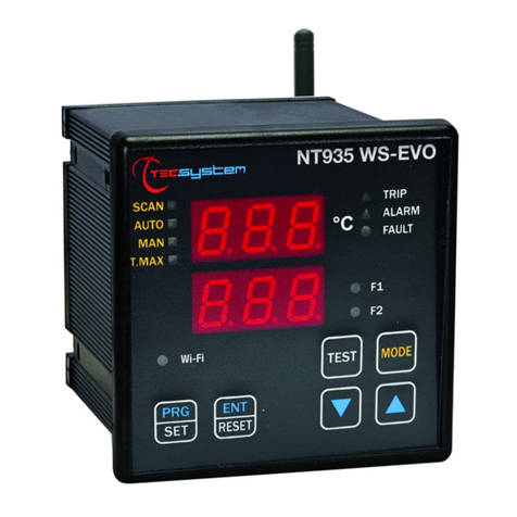
TECSYSTEM
TECSYSTEM NT935 WS User manual
TECSYSTEM
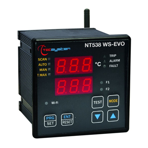
TECSYSTEM NT538 WS User manual
TECSYSTEM
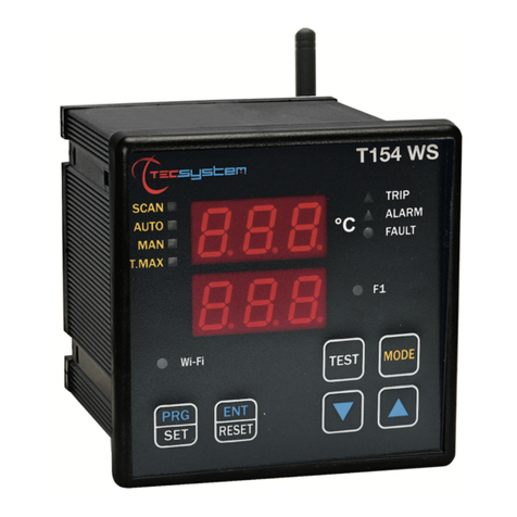
TECSYSTEM T154WS User manual
TECSYSTEM
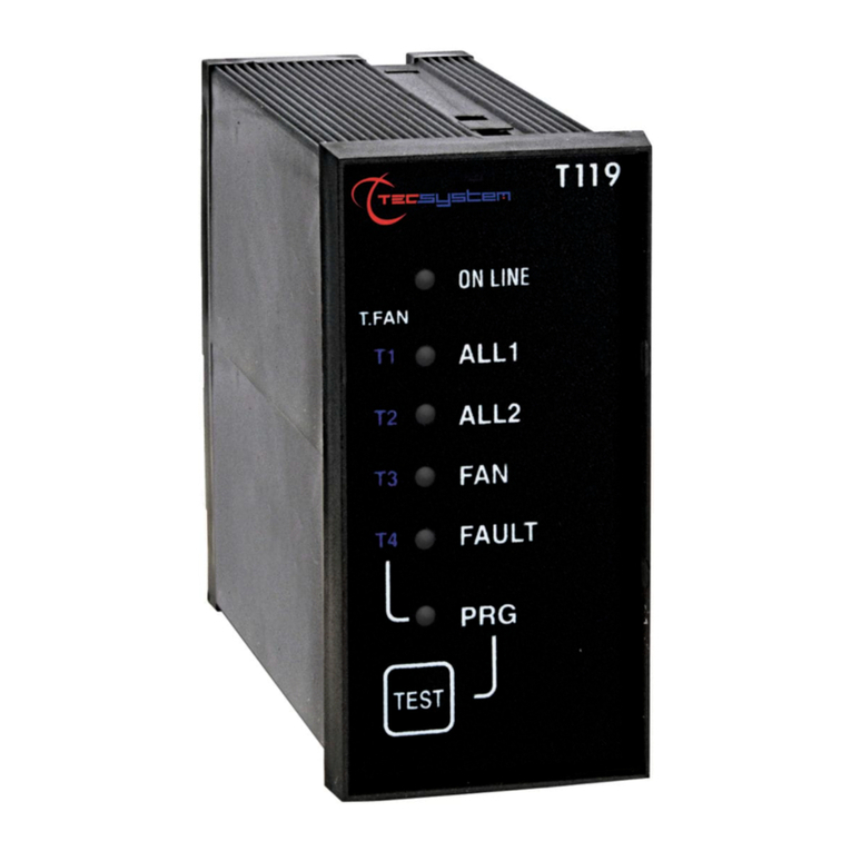
TECSYSTEM T119 User manual

TECSYSTEM
TECSYSTEM T119 DIN User manual
TECSYSTEM
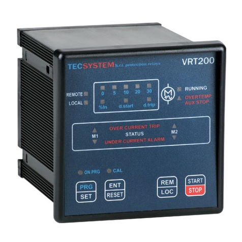
TECSYSTEM VRT200 User manual

TECSYSTEM
TECSYSTEM T119 DIN User manual
TECSYSTEM
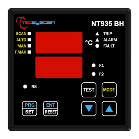
TECSYSTEM NT935BH-D User manual
TECSYSTEM
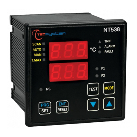
TECSYSTEM NT538 User manual
TECSYSTEM
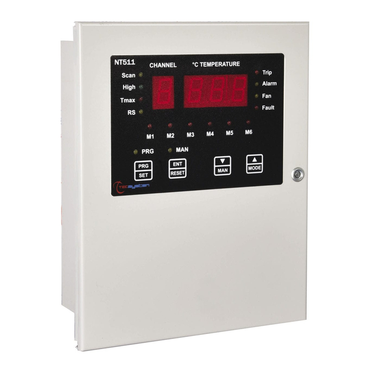
TECSYSTEM NT511Series User manual
