Em-Trak A100 Owner's manual

Document Title: em-trak A100 Class A AIS Fault Finding Guide
Author: Colin Horne
Number: 1.0
Issue: 1.0
04/01/2016 Company Confidential Page 1 of 9
2014 em-trak Marine Electronics Ltd
Em-trak Marine Electronics Ltd
A100 Class A AIS Transceiver
Fault Finding Guide
The information contained within this document is the copyright of Em-trak Marine Electronics Ltd.
No part of this document may be disclosed, reproduced or transmitted in any form, or by any means without the written permission Em-trak Marine Electronics Ltd. The term
document extends to all forms of media in which information may be embodied.

Document Title: em-trak A100 Class A AIS Fault Finding Guide
Author: Colin Horne
Number: 1.0
Issue: 1.0
04/01/2016 Company Confidential Page 2 of 9
2014 em-trak Marine Electronics Ltd
Introduction
This document is intended for use by customers of Em-trak Marine Electronics Ltd as a guide to fault finding on the A100 Class A, AIS
Transceiver (2010 onwards).
The guide gives a step by step guide on diagnosing faults and provides practical advice on a range of fixes and tips on ensuring the A100 Class
A AIS transceiver works correctly.
This guide offers information and advice on servicing and certain physical repairs for the em-trak A100.
It does not cover all possible repairs and fault conditions and we must insist that if a unit suffers a failure outside of
Those covered within this guide, then the unit should be returned for further inspection. Em-trak Marine Electronics Ltd
reserve the right to reject warranty claims if it is found that the terms of warranty conditions are breached.
If a fault persists after following the provided fault-finding guide, please submit a warranty/repair request via our dedicated support site at:
www.support.em-trak.com (Log-in required). Additional information such as answers to FAQs, software and manual downloads are also available
to registered users in the Knowledge Base area.
As well as this, you can check the status of existing and past requests and also subscribe to categories to receive automatic notifications
whenever new support articles or software updates are added to the site.
If you do not have log-in credentials for this site, or if you have forgotten your password, then please contact us by submitting a request from the
support site or email us at support@em-trak.com. We aim to respond to all enquiries and e-mails within 1 working day.

Document Title: em-trak A100 Class A AIS Fault Finding Guide
Author: Colin Horne
Number: 1.0
Issue: 1.0
04/01/2016 Company Confidential Page 3 of 9
2014 em-trak Marine Electronics Ltd
Inspect unit for obvious damage
/ signs of misuse
Unit has been opened
Warranty invalidated. If
boards damaged we
recommend entire unit
must be replaced
Unit has been damaged
thru misuse
Unit appears to be water
damaged
Unit is IP rated to IP52, so if unit appears to have been
immersed in water or subject to extensive water ingress,
this will be caused by incorrect installation or misuse.
Connect unit to:
- 12/24V Power Supply with Min 5A rating
- Suitable VHF antenna / Load *
- GPS antenna with clear view of sky
- PC / Laptop preloaded with
ConfigAIS software via serial connection
* Refer to Section 4 of this guide
for advice and notes about
Antenna systems.
Switch on power supply
to unit
Screen Lights Up and
Screen options appear
Screen Lights Up but no
text appears
Screen does not light up
at all.
Continue on next page
Visit www.support.em-trak.com and apply
latest MKD software update.
Check power supply
is active and
connection is correct
Unit will require further
inspection. Submit an RMA
request at
www.support.em-trak.com
Screen does not light up
at all.
Section 1: Initial inspection.
Software updated successfully but
screen still does not light up /
Software Update unsuccessful
Software updated
successfully
Power down
unit
Discoloured pixels / Lines
missing on screen
Check internal UI
PCA interface
connections
Unit has not been opened
/ no obvious signs of
damage or water ingress
Check D18/D29
D22, FS1 / R107 - 0Ω

Document Title: em-trak A100 Class A AIS Fault Finding Guide
Author: Colin Horne
Number: 1.0
Issue: 1.0
04/01/2016 Company Confidential Page 4 of 9
2014 em-trak Marine Electronics Ltd
Check controls and buttons are
serviceable by scrolling through
Menu screens.
Unit will not transmit without MMSI number. If fault symptom
is no TX, enter valid MMSI number via MKD or Config AIS
Controls unresponsive
Buttons sticking / Collapsed
Rotary control not turning concentrically
Check Own Vessel Data Screen
Valid MMSI number?
Other details appear to be correct
Go to Main Menu Screen
Select Maintenance
Select System Information
No MMSI
number
Details incorrect
/ Non alpha
numeric
characters
Check AIS and MKD software versions are
at latest release
(available at www.support.em-trak.com)
Old
Software
Update Software and
re-enter vessel details
Update
successful
Update
failure
Clean /Replace controls
as required
Press “Back” from System
Information and select
Diagnostics.
Select Internal GPS Status
Fix Status: GPS Locked
Satellites in view: (min of 3)
Satellites in use: (min of 3)
Mode: Autonomous
No GPS
reception
Ensure serviceable GPS antenna is connected correctly and
has a clear view of the sky. Wait 2 minutes.
NB:
“INTGPS” should
be displayed in top
right hand corner
of screen when
GPS fix is
established
No GPS
reception
Press Back from Internal GPS Status.
Back from Diagnostics
Back from Maintenance
Select Installation
Select Set Power
Enter Password
Select “High Power (12.5W)
Password
not
accepted?
Navigate to Installation Menu. Select Change Password and set
the new password to 'MIDSOMER' and leave the old password
blank. This will reset the password to the default of all zeros.
Continued
Check for 5V GPS
bias at connector
Check internal
connections
Continued
Unit may be “bricked”
Inspection required at
em-trak
Unit will require further inspection. Submit an
RMA request at
www.support.em-trak.com
Unit will require further
inspection. Submit an RMA
request at
www.support.em-trak.com

Document Title: em-trak A100 Class A AIS Fault Finding Guide
Author: Colin Horne
Number: 1.0
Issue: 1.0
04/01/2016 Company Confidential Page 5 of 9
2014 em-trak Marine Electronics Ltd
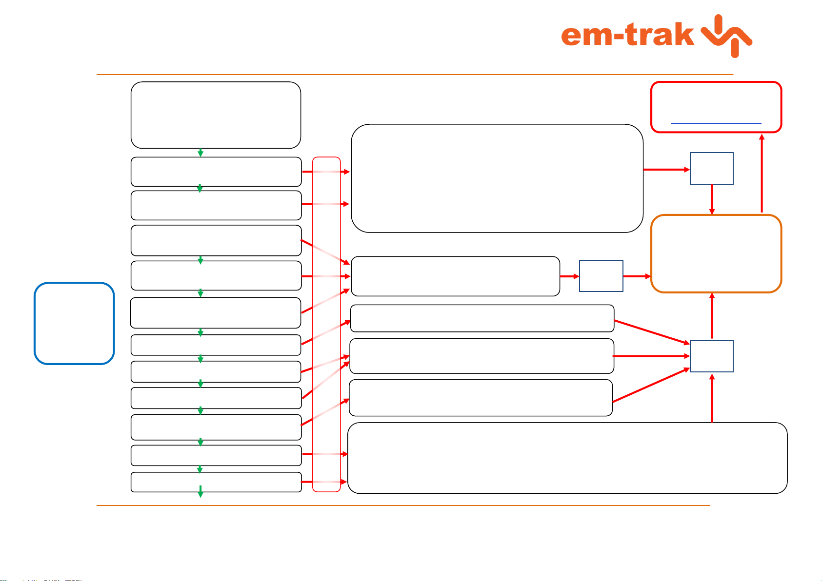
Press “Back” from Set Power
Press “Back” from Installation
Select “Maintenance” in Main Menu
Select “Diagnostics”
Select ADC and VSWR.
Check following values are as shown
Ch0: Tx Fwrd over 100 (typically around
140)
Ch1: Tx Rev under 50 (typically around 20)
Ch2: RSSI Rx1 about 50 (can typically vary
between low 40s and mid 60s)
Ch5: ADC channel 5- Below 70
Reverse Power –Typically around 15
Ch3: RSSI Rx2 about 50 (can typically vary
between low 40s and mid 60s)
Ch4: RSSI Rx3 about 50 (can typically vary
between low 40s and mid 60s)
Ch6: 6v8 Supply –About 06.8
Ch7: 13v8 Supply –About 13.8
VSWR Last Transmission: Values around
1.25:1 / 1.15:1)
Forward Power –Typically around 220
NB:
Presented values
are based on
assumption that
unit is set up as
described in
section 1 of this
document
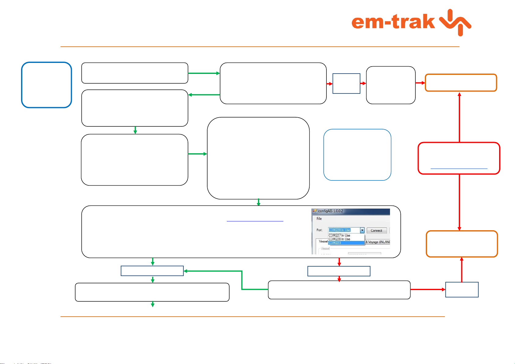
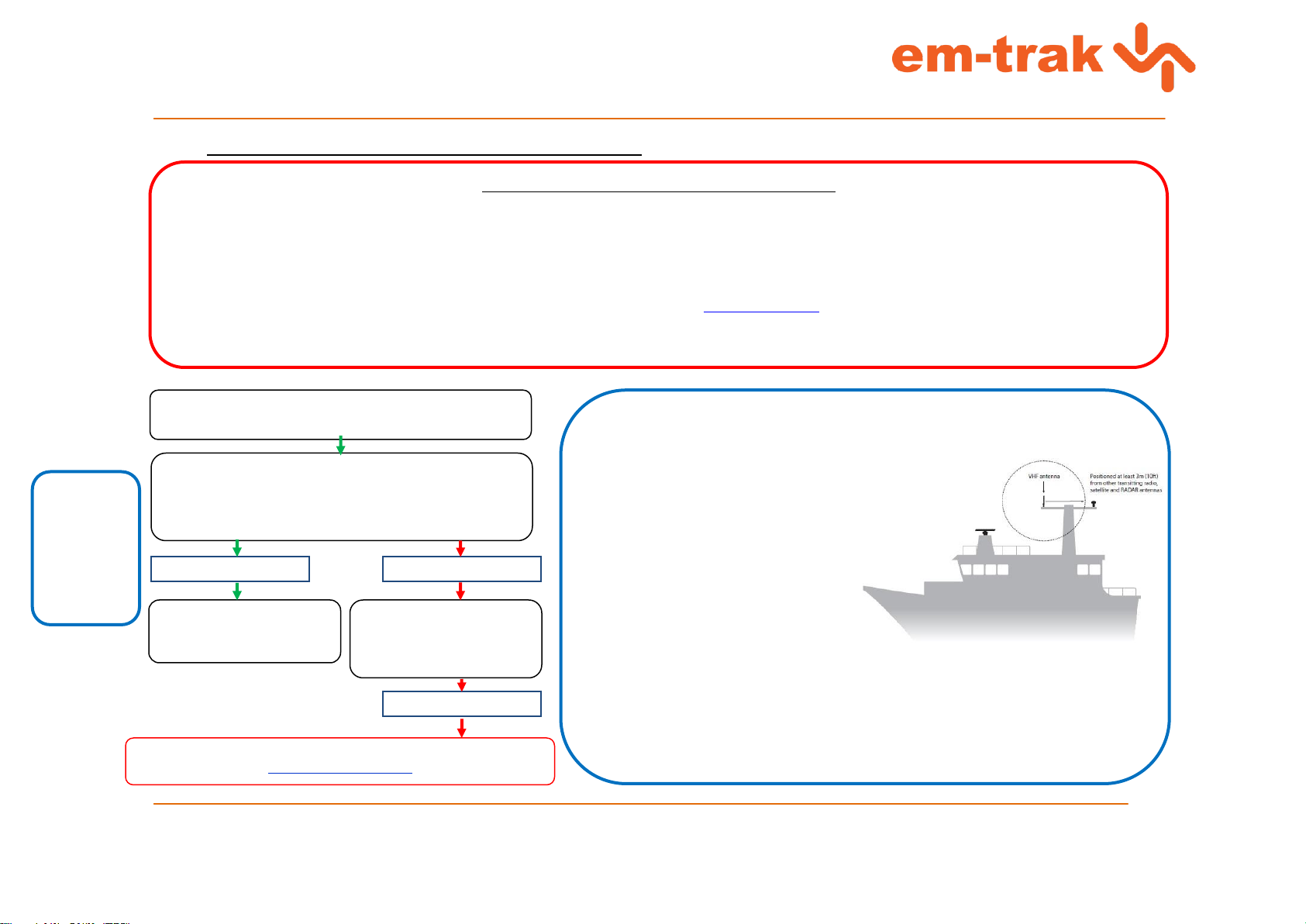
Check installation and ensure unit is not installed in strong direct
sunlight and air can circulate freely around the enclosure.
1 –Check connected Antenna System (Section 4)
2 –Check unit is in “High Power Mode” by navigating to “Installation” and
then “Set Power” (enter password)
- Highlight Low Power (1W) and press select. 1W should appear at
top of MKD
- Now, highlight High Power (12.5W) and press select. The 1W
symbol should disappear.
Return to ADC and VSWR menu and check values
Values
not
changed
Check all internal connections
Check Impedance: ≈4Ω
Check Software is up to date
(Remember to connect unit to
attenuator)
Check connected Antenna System (Section 4)
Return to ADC and VSWR menu and check values
Values
not
changed
Check power connections and supply to unit
Return to ADC and VSWR menu and check values
Check connected Antenna System (Section 4)
Return to ADC and VSWR menu and check values
1 –Check connected Antenna System (Section 4)
2 –Check unit is in “High Power Mode” by navigating to “Installation” and then “Set Power” (enter password)
- Highlight Low Power (1W) and press select. 1W should appear at top of MKD
- Now, highlight High Power (12.5W) and press select. The 1W symbol should disappear.
Return to ADC and VSWR menu and check values
Displayed value outside of typical range
Values
not
changed
Continued
Unit will require further
inspection. Submit an RMA
request at
www.support.em-trak.com

Document Title: em-trak A100 Class A AIS Fault Finding Guide
Author: Colin Horne
Number: 1.0
Issue: 1.0
04/01/2016 Company Confidential Page 6 of 9
2014 em-trak Marine Electronics Ltd
Press “Back” from ADC and VSWR
Select “Sensor Port Status”
GNSS in use: Internal GNSS
SOG in use: Internal
COG in use: Internal
Heading: Lost/Invalid
ROT in use: No valid information
UTC Clock: Lost
NB:
Presented values
are based on
assumption that
unit is static and
connected to
supplied GPS
Press “Back” from Sensor Status
Press “Back” from Maintenance
Select Installation
Select Sensor configuration
Enter Password
Values
not as
shown
Check GPS
antenna
connection and
installation is
correct
Check 5V Bias is present
- Highlight “Require DTM” and
press “Edit”.
- Set to “Yes” and press Save
- Highlight “Require DTM” again
and press “Edit”
- Set to “No” and press Save
again.
Check unit is set to factory defaults:
Sensor 1 Port Baud : 4800
Sensor 2 Port Baud : 4800
Sensor 3 Port baud : 4800
Long Range Port Baud : 4800
Beacon Port Baud : 4800
Ext KeyDisp Baud : 38400
Pilot Port Baud : 38400
RS232 Port Baud : 38400
Press Edit and use the Rotary knob
to change Baud rates if required.
Remember to “Save” any changes
Check connection from RS232 port on unit on test to PC (we recommend you use an Easysync
adaptor if a USB adaptor is required for your PC, contact us via www.support.em-trak.com for
advice on suitability of adaptors if unsure)
Open ConfigAIS software on connected PC and connect to unit on test by selecting
appropriate comm port from drop down list in top left hand corner of ConfigAIS.
NB:
Before tests to establish
faults with connection to
external devices/computers
etc. are carried out, it is
important to first ensure that
the unit is operating in its
factory “default” mode.
Connection established
Connection not established
Check Vessel Details, Alarm and Sensor Repeat settings are
as required and Serial Data Tab is showing NMEA sentences
Check connection to PC is sound. Check suitability of
adaptor if using USB-Serial converter.
Still no
connection
Proceed to Section 2
Check R396, R398 and
R406
Unit will require further
inspection. Submit an RMA
request at
www.support.em-trak.com

Document Title: em-trak A100 Class A AIS Fault Finding Guide
Author: Colin Horne
Number: 1.0
Issue: 1.0
04/01/2016 Company Confidential Page 7 of 9
2014 em-trak Marine Electronics Ltd
Section 2: Checking Software revision and applying updates.
Select Main Menu
Select Maintenance
Select System Information
Confirm displayed software versions
are as per latest release shown in
www.support.em-trak.com
Note about software revisions
We strongly recommend that all units returned for testing or servicing are checked to ensure they have the latest release of software installed. Software updates can contain
minor bug fixes and feature enhancements that will benefit the end user and may lessen the likelihood of a unit having issues in future.
In order to check for the latest versions of Poseidon (Class A) software, visit www.support.em-trak.com and log into the knowledge base to check for and download any new
software updates. Contact support@em-trak.com if you experience any problems logging into the site.
To be notified of new software releases, subscribe to the “Product Change Notification” section of the em-trak Class A Knowledge Base. You’ll then receive a message each time
a new update is available
Software is up to date.
Software versions are not up to date
or not visible on MKD
Navigate to:
http://support.em-
trak.com/forums/22976618-Device-
Software
(Login required)
Download required software and
apply update as per instructions
included with software
Software update fails
Software update successful
Unit may not be recoverable
Contact em-trak support for advice

Document Title: em-trak A100 Class A AIS Fault Finding Guide
Author: Colin Horne
Number: 1.0
Issue: 1.0
04/01/2016 Company Confidential Page 8 of 9
2014 em-trak Marine Electronics Ltd
Section 3: Basic Receive/Transmit check.
NB:
Suggested set-up of remote test unit:
Poseidon Class AIS Transceiver set up as follows:
- 5A 12V Power Supply
- VHF Antenna
- GPS antenna with good signal reception
- Power set to Low (1W)
- “Test” Vessel data programmed into Own Vessel Data
Ensure unit to be tested is set up and tested as
detailed in Section 1 of this guide.
To check content and frequency of transmission from Class A under
test, leave Remote unit on Target List screen.
When unit being tested appears on the Target List of the remote
unit, click on it to reveal transmitted vessel data.
Please allow at least 2 minutes for the unit on test to transmit.
Nothing
received on
remote unit
Transmission
received on
remote unit
Check unit under test is configured
with valid MMSI number.
Check unit under test for any active
alarms on MKD (refer to section 5 for
explanation of all alarms)
Check antenna system connections /
setup of both units are sound.
Nothing
received on
remote unit
Check transmitted information is correct (as per details entered
in unit under test)
Check connections
Check Impedance
Check Software
Attenuator in use?
Navigate to Target List on unit under test.
Remote unit details should appear.
Nothing
received on
test unit
Ensure remote unit is operating
correctly and is correctly setup.
Check unit under test for any active
alarms on MKD (refer to section 5 for
explanation of all alarms)
Check antenna system connections /
setup of both units are sound.
Nothing
received on
test unit
Navigate to Target Plot Screen.
Any active remote AIS transceivers
within range should also be displayed
here in relation to the location of the
test Class A, provided the test unit
has a fixed GPS position.
Test unit has INTGPS fix
but no targets received.
Unit will require further
inspection. Submit an RMA
request at
www.support.em-trak.com

Document Title: em-trak A100 Class A AIS Fault Finding Guide
Author: Colin Horne
Number: 1.0
Issue: 1.0
04/01/2016 Company Confidential Page 9 of 9
2014 em-trak Marine Electronics Ltd
Section 4: Antenna System Check (Class A unit only).
Important Note about Antenna Systems used for testing AIS
If you are planning on using an Antenna for the purposes of testing/evaluation of reported problems as part of your own in-house inspection process, please remember that there are factors
which may affect an antennas VSWR and performance such as:
- Electrical / RFI/ MEMIC Interference
- People walking past / working close to antennas
- Metallic objects / surfaces or structures
To ensure a consistent “control” of antenna system conditions, we recommend that you use a suitable dummy load or attenuator in place of VHF antennas on both test and remote units
used in in-house testing. We can recommend suitable loads for this purpose if required. Please contact support@em-trak.com if you’d like our help.
The following fault-guide will only allow you to diagnose if there is a fault with the antenna connections on the Class A itself. Please remember that issues such as VSWR alarms and TX
Malfunctions can be caused through problems with faulty connectors, cables and antennas and may not indicate a fault with the unit itself.
Before proceeding with this guide, we advise that you consider the suitability of the antenna and its installation location when diagnosing a fault displayed on a returned unit.
Unit displays VSWR / TX Malfunction Alarms or customer
reports VSWR error / alarm as fault condition
NB:
Recommended VHF antenna specification:
Band: Marine VHF band (nominally 156MHz to 162MHz)
Impedance: 50 Ohms
Gain: 3dBi
VSWR: <1.5:1 at resonant frequency
Max power: Typically >25W
Polarisation: Vertical
Bandwidth: Typically 6MHz
Cable: RG58 or better. Note the IMO recommend
RG214 or better for SOLAS installations
Connector: PL-259 (sometimes called ‘UHF’)
General vessel antenna installation advice:
- Locate Antenna as high and as far away
from other antennas as possible
- Do not install antenna adjacent to large metallic surfaces
- Any external connectors on system should be waterproof by design
- Antenna system cables should be installed in cable channels at least 10cm (4ins) away from
power cables
- Ideally the AIS VHF Antenna should be mounted directly above or below the ships primary
VHF radiotelephone antenna, with no horizontal separation and with a minimum of 2m vertical
separation. If it is located on the same horizontal level as other antennas, the distance apart
should be at least 10m
Select Main Menu
Select “Maintenance”
Select “Diagnostics”
Select ADC and VSWR.
Check values are as defined in Section 1
NB:
VSWR, TX
Frwd/TX
Rev/Frwd
Pwr/Rev Pwr
values can
only be
displayed if the
unit has
transmitted
Values incorrect
Check all connectors /
cables / antenna for
damage and correct fitting
Values still incorrect
Unit will require further inspection. Submit an RMA request at
www.support.em-trak.com
Values correct
Check customers antenna
type and installation is as
per advice
Other manuals for A100
2
Table of contents
Other Em-Trak Marine Equipment manuals
Popular Marine Equipment manuals by other brands

Federal Signal Corporation
Federal Signal Corporation LP7 Installation and service instructions

DIGITAL YACHT
DIGITAL YACHT ENGINELINK NMEA 2000 ENGINE MONITOR Installation and instruction manual

Garmin
Garmin GSD 26 installation instructions

Garmin
Garmin ECHOMAP Ultra Series installation instructions

Raytheon
Raytheon 138-119 Operator's and service manual

JRC
JRC JHS-180 instruction manual