manuals.online logo
Brands
  1. Home
  2. •
  3. Brands
  4. •
  5. Garmin
  6. •
  7. Marine Equipment
  8. •
  9. Garmin ECHOMAP Ultra Series User manual

Garmin ECHOMAP Ultra Series User manual

ECHOMAP™ULTRA
INSTALLATION
INSTRUCTIONS
Important Safety Information
WARNING
See the Important Safety and Product Information guide in the
product box for product warnings and other important
information.
When connecting the power cable, do not remove the in-line
fuse holder. To prevent the possibility of injury or product
damage caused by fire or overheating, the appropriate fuse
must be in place as indicated in the product specifications. In
addition, connecting the power cable without the appropriate
fuse in place voids the product warranty.
CAUTION
Always wear safety goggles, ear protection, and a dust mask
when drilling, cutting, or sanding.
NOTICE
When drilling or cutting, always check what is on the opposite
side of the surface.
To obtain the best performance and to avoid damage to your
boat, install the device according to these instructions.
Read all installation instructions before proceeding with the
installation. If you experience difficulty during the installation,
contact Garmin® Product Support.
Tools Needed
• Drill
• Drill bits
◦ Bail mount: drill bits and screws appropriate for the
surface and hardware
◦ Flush mount: 3.2 mm (1/8 in.) and 9.5 mm (3/8 in.) drill bits
• #2 Phillips screwdriver
• Jigsaw or rotary tool
• File and sandpaper
• Marine sealant (optional)
Mounting Considerations
You can flush mount the device in the dashboard or bail mount
the device on the dashboard.
When selecting a mounting location, observe these
considerations.
• The mounting location must provide a clear view of the
screen and access to the keys on the device.
• The mounting location must be sturdy enough to support the
device and the mount.
• The cables must be long enough to connect the components
to each other and to power.
• To avoid interference with a magnetic compass, do not install
the device closer to a compass than the compass-safe
distance value listed in the product specifications.
Bail Mounting the Device
NOTICE
If you are mounting the bracket on fiberglass with screws, it is
recommended to use a countersink bit to drill a clearance
counterbore through only the top gel-coat layer. This will help to
avoid cracking in the gel-coat layer when the screws are
tightened.
1Select the mounting hardware appropriate for your mounting
surface and for the bail-mount bracket.
2Using the bail-mount bracket as a template, mark the pilot
holes .
3Using a drill bit appropriate for the mounting hardware, drill
the four pilot holes.
4Using the selected mounting hardware, secure the bail-mount
bracket to the mounting surface.
5Place the cradle into the bail-mount bracket, and tighten
the bail-mount knobs .
6Connect all necessary cables to the cradle (Connector View,
page 2), and spin the locking rings clockwise to lock the
cables to the cradle.
NOTICE
To prevent corrosion of the metal contacts, cover unused
connectors with the attached weather caps.
Flush Mounting the Device
NOTICE
Be careful when cutting the hole to flush mount the device.
There is only a small amount of clearance between the case and
the mounting holes, and cutting the hole too large could
compromise the stability of the device after it is mounted.
Using a metal pry tool such as a screwdriver can damage the
trim caps and the device. Use a plastic pry tool when possible.
You can mount the device in your dashboard using the flush-
mount template and appropriate hardware.
1Secure the template to the mounting location.
TA-2019/5173
GUID-7EC09750-0897-4743-9159-D226DE691962 v4February 2020
2Using a 13 mm (1/2 in.) drill bit, drill one or more of the holes
inside the corners of the solid line on the template to prepare
the mounting surface for cutting.
3Using a jigsaw or rotary cutting tool, cut the mounting surface
along the inside of the solid line indicated on the template.
4Place the device into the cutout to test the fit.
5Use a pry tool, such as a flat piece of plastic or a screwdriver,
to carefully pry up the corners of the trim caps, and remove
the trim caps.
6Place the device in the cutout, and ensure the mounting
holes on the device line up with the pilot holes on the
template.
7If the mounting holes on the device do not line up with the
pilot holes on the template, mark the new hole locations.
8Using a 3.2 mm (1/8 in.) drill bit, drill the pilot holes.
9Remove the template from the mounting surface.
10Place the device in the cradle (Installing the Device in the
Cradle, page 3).
11Install the rubber gasket on the back of the device.
The rubber gasket has adhesive on the back. Make sure you
remove the protective liner before installing it on the device.
12Connect all necessary cables (Connector View, page 2),
and spin the locking rings clockwise to secure the cables to
the cradle before placing it into the cutout.
NOTICE
To prevent corrosion of the metal contacts, cover unused
connectors with weather caps.
13Place the device into the cutout.
14Secure the device to the mounting surface using the included
screws.
15Install the trim caps by snapping them in place around the
edges of the device.
Connection Considerations
After connecting the cables to the cradle, tighten the locking
rings to secure each cable.
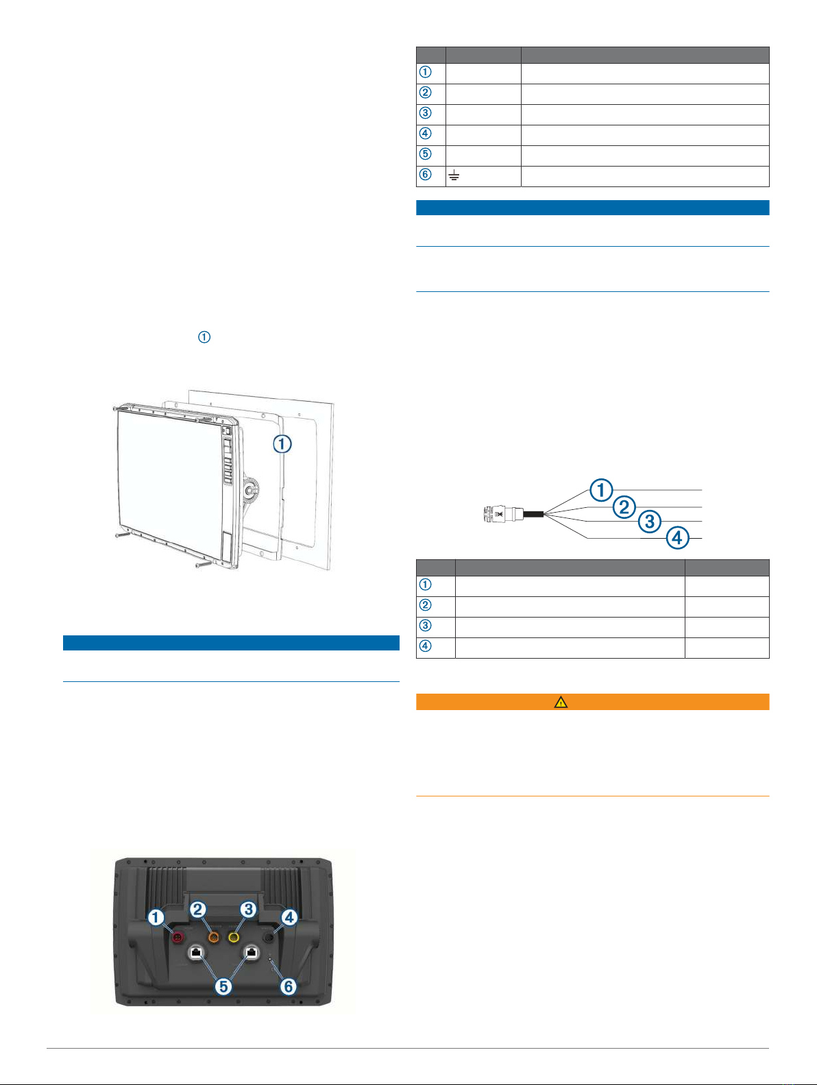
Connector View
Item Label Description
POWER Power and NMEA® 0183 devices
12 PIN XDCR 12-pin transducer
LVS XDCR Panoptix™ LiveScope™ LVS12 12-pin transducer
NMEA 2000 NMEA 2000® network
NETWORK ECHOMAP network for sonar sharing
Ground screw
NOTICE
To prevent corrosion of the metal contacts, cover unused
connectors with weather caps.
To comply with regulations and to reduce noise, snap the ferrite
beads on the network and transducer cables, near the
connectors.
Power and Data Cable
• The wiring harness connects the device to power and NMEA
0183 devices.
• If you are not connecting NMEA 0183 devices, disregard the
blue and brown wires.
• The device has one internal NMEA 0183 port that is used to
connect to NMEA 0183 compliant devices.
• If it is necessary to extend the power and ground wires, you
must use 1.31 mm2 (16 AWG) or larger wire.
• If it is necessary to extend the NMEA 0183 or alarm wires,
you must use .33 mm2 (22 AWG) wire.
Item Wire Function Wire Color
NMEA 0183 internal port Rx (in) Brown
NMEA 0183 internal port Tx (out) Blue
Ground (power and NMEA 0183) Black
Power Red
Connecting to Power
WARNING
When connecting the power cable, do not remove the in-line
fuse holder. To prevent the possibility of injury or product
damage caused by fire or overheating, the appropriate fuse
must be in place as indicated in the product specifications. In
addition, connecting the power cable without the appropriate
fuse in place voids the product warranty.
You should connect the red wire to the same battery through the
ignition or another manual switch to turn the device on and off.
1Route the power cable between the power source and the
device.
2Connect the red power wire to the ignition or another manual
switch, and connect the switch to the positive (+) battery
terminal if necessary.
3Connect the black wire to the negative (-) battery terminal or
to ground.
4Connect the power cable to the device, and turn the locking
ring clockwise to tighten it.
Connecting the Device to a Transducer
Go to garmin.com/transducers or contact your local Garmin
dealer to determine the appropriate type of transducer for your
needs.
2
1Follow the instructions provided with your transducer to
correctly install it on your boat.
2Route the transducer cable to the back of your device, away
from sources of electrical interference.
3Connect the transducer cable to the appropriate port on the
cradle.
NMEA 2000 Considerations
NOTICE
If you are connecting to an existing NMEA 2000 network,
identify the NMEA 2000 power cable. Only one NMEA 2000
power cable is required for the NMEA 2000 network to operate
properly.
A NMEA 2000 Power Isolator (010-11580-00) should be used in
installations where the existing NMEA 2000 network
manufacturer is unknown.
If you are installing a NMEA 2000 power cable, you must
connect it to the boat ignition switch or through another in-line
switch. NMEA 2000 devices will drain your battery if the NMEA
2000 power cable is connected to the battery directly.
You can connect your device to a NMEA 2000 network on your
boat to share data from NMEA 2000 compatible devices such as
sensors or a VHF radio. The necessary NMEA 2000 cables and
connectors are sold separately.
If you are unfamiliar with NMEA 2000, you should read the
“NMEA 2000 Network Fundamentals” chapter of the Technical
Reference for NMEA 2000 Products. You can find this document
using the "Manuals" link on the product page for your device at
garmin.com.
The port labeled NMEA 2000 on the cradle is used to connect it
to a standard NMEA 2000 network.
Item Description
ECHOMAP Ultra device
NMEA 2000 drop cable
NMEA 2000 power cable
Ignition or in-line switch
12 Vdc power source
NMEA 2000 terminator or backbone cable
NMEA 2000 T-connector
NMEA 2000 terminator or backbone cable
Installing the Device in the Cradle
After the cables are connected to the cradle, you can quickly
place the device in the cradle.
1Press the button on the release lever and lift the lever to
unlock it.
2Place the base of the device in the bottom of the cradle.
3Lift the lever.
4Tilt the top of the device toward the cradle.
5Press the button on the lever, and push the lever down until
the device clicks in place.
Removing the Device from the Cradle
1Press the button on the release lever on the cradle, and pull
the lever up.
2Tilt the device forward, and lift the device out of the cradle.
Specifications
All Models
Material Polycarbonate plastic
Water rating IEC 60529 IPX71
Temperature range From -15° to 55°C (from 5° to 131°F)
Compass-safe distance 65 cm (25.6 in.)
Clearance to nearest
obstruction
150 mm (6 in.)
Input voltage From 9 to 18 Vdc
Fuse 8 A
NMEA 2000 LEN @ 9 Vdc 1
NMEA 2000 draw 39 mA max.
Memory card 2 microSD® card slots; 32 GB max.
card size
10-Inch Models
Dimensions (W x H x D) 29.5 x 19.5 x 9.8 cm (11.6 x 7.7 x
3.9 in.)
Display size (W x H) 21.7 x 13.6 cm (8.5 x 5.4 in.)
25.4 cm (10 in.) diagonal
Weight 1.8 kg (4.1 lb.)
Max. power draw 34 W
Typical current draw at 12 Vdc
(RMS)
2.8 A
Max. current draw at 12 Vdc (RMS) 3 A
Wireless frequencies and protocols 2.4 GHz @ 17.2 dBm nominal
12-Inch Models
Dimensions (W x H x D) 34.1 x 22.9 x 9.8 cm (13.4 x 9.0
x 3.9 in.)
Display size (W x H) 26.1 x 16.3 cm (10.3 x 6.4 in.)
30.7 cm (12.1 in.) diagonal
Weight 2.5 kg (5.5 lb.)
Max. power draw 34 W
1 The device withstands incidental exposure to water of up to 1 m for up to 30 min.
For more information, go to www.garmin.com/waterrating.
3
Typical current draw at 12 Vdc
(RMS)
3 A
Max. current draw at 12 Vdc (RMS) 3.3 A
Wireless frequencies and protocols 2.4 GHz @ 18.5 dBm nominal
NMEA 2000 PGN Information
Transmit and Receive
PGN Description
059392 ISO acknowledgment
059904 ISO request
060928 ISO address claim
126208 NMEA: Command, request, and acknowledge group function
126996 Product information
127250 Vessel heading
128259 Speed: Water referenced
128267 Water depth
129539 GNSS DOPs
129799 Radio frequency, mode, and power
130306 Wind data
130312 Temperature
Transmit
PGN Description
126464 Transmit and receive PGN list group function
127258 Magnetic Variance
129025 Position: Rapid update
129026 COG and SOG: Rapid update
129029 GNSS position data
129283 Cross track error
129284 Navigation data
129285 Navigation route and waypoint info
129540 GNSS satellites in view
Receive
PGN Description
127245 Rudder
127250 Vessel heading
127488 Engine parameters: Rapid update
127489 Engine parameters: Dynamic
127493 Transmission parameters: Dynamic
127498 Engine parameters: Static
127505 Fluid level
129038 AIS class A position report
129039 AIS class B position report
129040 AIS class B extended position report
129794 AIS class A static and voyage related data
129798 AIS SAR aircraft position report
128000 Nautical leeway angle
129802 AIS safety-related broadcast message
129808 DSC call information
130310 Environmental parameters
130311 Environmental parameters (obsolete)
130313 Humidity
130314 Actual pressure
130576 Small craft status
© 2019 Garmin Ltd. or its subsidiaries
Garmin® and the Garmin logo are trademarks of Garmin Ltd. or its subsidiaries,
registered in the USA and other countries. ECHOMAP™ is a trademark of Garmin Ltd. or
its subsidiaries. These trademarks may not be used without the express permission of
Garmin.
NMEA®, NMEA 2000®, and the NMEA® logo are registered trademarks of the National
Marine Electronics Association. microSD® and the microSD logo are trademarks of
SD-3C, LLC.
© 2019 Garmin Ltd. or its subsidiaries support.garmin.com

Other manuals for ECHOMAP Ultra Series

2

Other Garmin Marine Equipment manuals

Garmin GHP 10 User manual

Garmin

Garmin GHP 10 User manual

Garmin GC 12 User manual

Garmin

Garmin GC 12 User manual

Garmin GHC 20 User manual

Garmin

Garmin GHC 20 User manual

Garmin Panoptix Livescope User manual

Garmin

Garmin Panoptix Livescope User manual

Garmin Gladiator TR-1 User manual

Garmin

Garmin Gladiator TR-1 User manual

Garmin FUSION APOLLO MS-WB675 User manual

Garmin

Garmin FUSION APOLLO MS-WB675 User manual

Garmin GNX Wind User manual

Garmin

Garmin GNX Wind User manual

Garmin 600 T-TOP User manual

Garmin

Garmin 600 T-TOP User manual

Garmin NMEA 2000 Use and care manual

Garmin

Garmin NMEA 2000 Use and care manual

Garmin GMI 10 Digital Marine Instrument Display User manual

Garmin

Garmin GMI 10 Digital Marine Instrument Display User manual

Garmin GSD 26 User manual

Garmin

Garmin GSD 26 User manual

Garmin GPSMAP 198C User manual

Garmin

Garmin GPSMAP 198C User manual

Garmin GPSMAP 8700 User manual

Garmin

Garmin GPSMAP 8700 User manual

Garmin GMI 20 User manual

Garmin

Garmin GMI 20 User manual

Garmin GSA 8X User manual

Garmin

Garmin GSA 8X User manual

Garmin LIVESCOPE User manual

Garmin

Garmin LIVESCOPE User manual

Garmin GHC 10 Instruction manual

Garmin

Garmin GHC 10 Instruction manual

Garmin GMI 20 User manual

Garmin

Garmin GMI 20 User manual

Garmin 22 User manual

Garmin

Garmin 22 User manual

Garmin GPSMAP 168 Sounder User manual

Garmin

Garmin GPSMAP 168 Sounder User manual

Garmin TR-1 Gold User manual

Garmin

Garmin TR-1 Gold User manual

Garmin GPSMAP 527  Guide Service manual

Garmin

Garmin GPSMAP 527 Guide Service manual

Garmin AIS User manual

Garmin

Garmin AIS User manual

Garmin GSD 26 User manual

Garmin

Garmin GSD 26 User manual

Popular Marine Equipment manuals by other brands

Furuno IF-7000 Operator's manual

Furuno

Furuno IF-7000 Operator's manual

IMCO SCX Series Information, Operation and Maintenance

IMCO

IMCO SCX Series Information, Operation and Maintenance

Furuno FI-301 Operator's manual

Furuno

Furuno FI-301 Operator's manual

GUIDANCE MARINE RangeGuard Installer's guide

GUIDANCE MARINE

GUIDANCE MARINE RangeGuard Installer's guide

Orbit OceanTRx7 Technical notes

Orbit

Orbit OceanTRx7 Technical notes

Elmdene INT400 instruction sheet

Elmdene

Elmdene INT400 instruction sheet

Maxwell RC12 manual

Maxwell

Maxwell RC12 manual

Pfannenberg Intense BR 50-SM quick guide

Pfannenberg

Pfannenberg Intense BR 50-SM quick guide

Reson SeaBat 8101 Operator's manual

Reson

Reson SeaBat 8101 Operator's manual

Raymarine Viewable Marine Displays user guide

Raymarine

Raymarine Viewable Marine Displays user guide

Bennett Marine ES2000 quick start guide

Bennett Marine

Bennett Marine ES2000 quick start guide

E2S IS-pA1 instruction manual

E2S

E2S IS-pA1 instruction manual

Kenwood KMR-700U - Radio / Digital Player instruction manual

Kenwood

Kenwood KMR-700U - Radio / Digital Player instruction manual

Furuno NAVNET 3D MFDBB Software instructions

Furuno

Furuno NAVNET 3D MFDBB Software instructions

Kongsberg EA 600 instruction manual

Kongsberg

Kongsberg EA 600 instruction manual

Seiwa EXPLORER 23 installation manual

Seiwa

Seiwa EXPLORER 23 installation manual

MIVARDI M1300 user manual

MIVARDI

MIVARDI M1300 user manual

hyfire HFI-EBS-06 manual

hyfire

hyfire HFI-EBS-06 manual

manuals.online logo
manuals.online logoBrands
  • About & Mission
  • Contact us
  • Privacy Policy
  • Terms and Conditions

Copyright 2025 Manuals.Online. All Rights Reserved.