AB Marine Gori User manual

[Gori 2-Blade Saildrive Propeller Installation and Maintenance Instructions, 6/21/2022]
Distributed By
AB Marine, Inc ▪ 747 Aquidneck Ave ▪ Middletown ▪ RI 02842
Tel: 401-847-7960 ▪ Fax: 401-849-0631
Email: Sales@AB-Marine.com ▪ Website: www.AB-Marine.com
Gori 2-Blade Saildrive Installation Instructions
Table of Contents
Gori 2-Blade Saildrive Installation Instructions...................................................................................1
Parts List....................................................................................................................................1
Schematic Drawings ....................................................................................................................2
Saildrive Nut Socket Sizes ............................................................................................................2
Torque Settings...........................................................................................................................2
Installing the Propeller .................................................................................................................3
Removing the Propeller ................................................................................................................5
Replacing the Collar Zinc ..............................................................................................................5
Removing the blades from the Blade Housing ....................................................................................6
Operating Instructions ....................................................................................................................7
Ahead ........................................................................................................................................7
Astern........................................................................................................................................7
Sailing .......................................................................................................................................7
Cleaning and Maintenance...............................................................................................................8
Annual Maintenance.....................................................................................................................8
Underwater Installation................................................................................................................8
Parts List
1
Hub
1 x each
2
Blades
2 x each
3
Pins
2 x each
4
Washer
1 x each
5
Shaft nut
1 x each
6
Split pin
1 x each not used on all installations
7
Allen screws
2 x each
8
Allen screws
2 x each
9
Locking bolt
1 x each
10
Collar zinc
1 x each … 2 x halves
11
Zinc screws
4 x each
12
Loctite 243
1 x bottle
13
Allen key
4mm
14
Allen key
5mm

[Gori 2-Blade Saildrive Propeller Installation and Maintenance Instructions, 6/21/2022]
Distributed By
AB Marine, Inc ▪ 747 Aquidneck Ave ▪ Middletown ▪ RI 02842
Tel: 401-847-7960 ▪ Fax: 401-849-0631
Email: Sales@AB-Marine.com ▪ Website: www.AB-Marine.com
Schematic Drawings
Saildrive Nut Socket Sizes
2-Blade ~ Saildrive
11.5" to 12.5" diameter for Bukh DV-8
SME and DV-10 LSME
22 mm socket
2-Blade ~ Saildrive
11.5" to 12.5" diameter for Volvo Penta
MB2A with 50S saildrive
19 mm socket
2-Blade ~ Saildrive
13" to 18" diameter
24 mm socket
Torque Settings
Saildrive Model
Fastener Type
Fastener Size
Torque
Yanmar SD20/25, 30/31,
Volvo, Lombardini, Beta,
Nanni, Technodrive SP60
Saildrive Nut
M16 X 2.0
45 ft/lb (60Nm)
Yanmar SD40/50/60
Saildrive Nut
M20 x 2.0
72 ft/lb (88-
98Nm)
[All]
Nut Locking Bolt
M8
9-10 ft/lb
(15NM)

[Gori 2-Blade Saildrive Propeller Installation and Maintenance Instructions, 6/21/2022]
Distributed By
AB Marine, Inc ▪ 747 Aquidneck Ave ▪ Middletown ▪ RI 02842
Tel: 401-847-7960 ▪ Fax: 401-849-0631
Email: Sales@AB-Marine.com ▪ Website: www.AB-Marine.com
Installing the Propeller
The propeller is delivered assembled. This ensures that at the factory the propeller has been checked and
balanced before shipping.
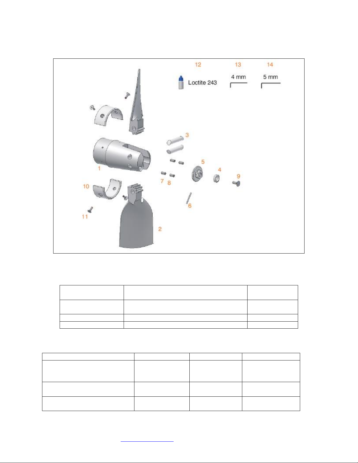
1. Take the propeller apart –Remove the two (7&8) M8 Allen screws per blade pin. Push blade pins (3)
out with a wooden dowl to not damage the pin end. The blades, pins and hub are all marked (#1 &
#2) so as to re-assemble in the correct balanced location. Note: here are two (2) Allen screws per
blade pin.
2. Ensure that the Saildrive spacer supplied with the saildrive unit is in place at the forward end of the
output shaft. The forward face of the saildrive propeller hub presses against this saildrive spacer to
keep the retaining cap/blade housing clear of the saildrive leg zinc.
3. Lightly smear spline grooves and shaft with waterproof lithium anti-corrosion lubricant as specified by
saildrive manufacturer.
4. Slide the hub (1) onto the shaft spline. Check that the supplied shaft nut (5), threads on to the end of
the output shaft
5. Apply locking glue (Loctite 243) to the shaft and nut threads and install the GORI supplied nut (5) and
tighten/torque (see above torque settings) the nut. To tighten the nut to the specified torque for your
saildrive model, move the shift lever to Ahead and hold the crankshaft V-Pulley clamp nut with a
wrench to stop the propeller shaft from rotating. Put a dab on the shaft thread after the nut is torqued
in place. This is required by Loctite. See above socket sizes.
The supplied Loctite 243 locking glue is “Blue”and is for disassemble of parts with
hand tools. Loctite “Red” is permanent and requires heat to undo (450°F for 5
minutes). Applying locking glue correctly is important. The surfaces must be clean
and degreased. Glue needs to be put in the hole as well as threads for blind holes such
as with the Locking bolt.
It is very important to always use the Gori supplied propeller nut for the installation.
An incorrect nut can lead to loss of the propeller, part of the propeller or cause an
electrical connection between the propeller and the saildrive.
6. Install the two (2) nut locking M6x6 setscrews into the two threaded holes in the nut aft face (supplied
in parts bag) with Loctite applied to threads. Tighten using 3mm Allen wrench. On older nut versions
setscrew holes may not be present.
7. Smear Loctite 243 on the thread of the nut-locking bolt (9). Place the washer (4) into the shaft nut
and then screw in the nut-locking bolt (9) using a 5mm Allen key (19). Tighten Locking Bolt to 9-10
ft/lbs(15NM) of torque.
8. On older saildrive models there may be a hole drilled through the shaft thread at the end of the shaft.
If so tighten the nut to required torque and then align the shaft tit end hole with the closest hole on
the shaft nut (5) and insert the cotter pin (6) and bend over.
On newer GORI models (2020+) the shaft nut has two(2) M4 locking setscrews threaded into the
encapsulated washer part of the nut. Apply Locking glue to the two(2) set screws & tighten them into
the aft face of the prop hub as a double locking method for securing the nut.

[Gori 2-Blade Saildrive Propeller Installation and Maintenance Instructions, 6/21/2022]
Distributed By
AB Marine, Inc ▪ 747 Aquidneck Ave ▪ Middletown ▪ RI 02842
Tel: 401-847-7960 ▪ Fax: 401-849-0631
Email: Sales@AB-Marine.com ▪ Website: www.AB-Marine.com
9. Mount the blades (2) and the pins (3) to the hub. Be sure that you mount them in accordance to their
numbers, i.e. #1 and #2 positions. Lightly grease the moving parts of the blades -gears- with water
resistant grease after cleaning and repair.
10. Apply Loctite-243 on the threads of the Four(4) M8 Allen screws (7&8) & Install into aft end of hub
forks screwing them in until they tighten against the blade pin. Total four (4) –two (2) per blade pin.
The second screw is a locking screw. Tighten both in place using supplied Allen Wrench. On 16.5-18”
dia. the longer setscrew goes in first, the short one on top.
11. Check that the blades will move freely from open to closed.
Your Gori is water lubricated. At hauling, after cleaning, & before storage, put a light smear of a
waterproof grease over the blade teeth, blade cheeks and hub fork housing contact points. This will allow
you to check blade operation and stop oxidization of the metal when out of the water.

[Gori 2-Blade Saildrive Propeller Installation and Maintenance Instructions, 6/21/2022]
Distributed By
AB Marine, Inc ▪ 747 Aquidneck Ave ▪ Middletown ▪ RI 02842
Tel: 401-847-7960 ▪ Fax: 401-849-0631
Email: Sales@AB-Marine.com ▪ Website: www.AB-Marine.com
Removing the Propeller
Do not use oil or any petroleum product on Flexible Bushing!
1. Remove the two (7&8) M8 Allen screws per blade pin. There are two (2) Allen screws per blade pin, a
total of four(4). Push the two blade pin (3) out using a wooden dowl - note blades, pins and hub are
numbered for re-assembly.
2. Unscrew the nut-locking bolt (4.1) with the washer (4) using a 5mm Allen key (19). Older models may
have a cotter pin which needs to be removed.
3. Unscrew the two (2) M5 Locking setscrews in the face of the integrated nut washer. Note: this is on
2020+ models.
4. Unscrew the shaft nut (5) counterclockwise using required socket (See above). It may be necessary to
lock the output shaft when undoing the shaft nut. To do this either put the engine into reverse or use
a strap wrench to hold the inner hub (1).
5. Pull/slide the hub (1), off the output shaft spline. Ensure that the Saildrive spacer supplied with the
saildrive unit is in place at the forward end of the output shaft.
Replacing the Collar Zinc
This should be done if more than 50% of the zinc (17), has been eroded away.
1. Remove the 4 x Allen-head bolts (11) and remove the old zinc.
2. Clean the surface of the propeller hub to ensure a good clean contact between the hub and the new
zinc
3. Install the new zinc (10) using the Loctite 243 (supplied) on each of the 4 x Allen-head bolts

[Gori 2-Blade Saildrive Propeller Installation and Maintenance Instructions, 6/21/2022]
Distributed By
AB Marine, Inc ▪ 747 Aquidneck Ave ▪ Middletown ▪ RI 02842
Tel: 401-847-7960 ▪ Fax: 401-849-0631
Email: Sales@AB-Marine.com ▪ Website: www.AB-Marine.com
Removing the blades from the Blade Housing
This must only be done when cleaning and full service of the propeller is required.
Blades are not removed for the installation and removal of the propeller.
To remove blades –the center Fixing Bolt “MUST” be removed first!
1. Remove the zinc centre bolt (8) and the zinc anode (7), using a 5mm Allen key (19).
2. On propellers 18.0” diameter and larger it will also be necessary to: Remove the threaded pin (9)
using a 6mm Allen key (20), then Remove the fixing bolt (10) using a 5mm Allen key (19).
Failure to remove all these pins (8-9-10) first, will result in damage to the internal
threads of the blade pins (11) & blade housing.
3. Disassemble the blade pins (11 & 11.1) from the blade housing using a 6mm Allen key (20). Note that
blades, pins and the housing are matched and numbered. They should only be reassembled in the
correct location … that is #1 - # 2 - # 3.
4. Remove the blades.
5. Remove the gear-wheel (13) and the spacer (14).
6. Remove the flexible stops (15) using either a flat blade screw driver or pliers.
7. When re-mounting the blades and gears to the housing it is important to apply Loctite 243 to blade
pins & lock bolts (11 +11.1), fixing lock pin (10), threaded pin (9), zinc bolt (8).
8. The lock bolt (10), fixing bolt (8) and aft zinc bolt (8) are the very last items to be reassembled. Item
9 & 10 on 18-20” dia. only. Item 8 in place of 9 & 10 on 15”-16.5” dia.
9. Be sure that all components fit back together and that the blade pins (11) are located as before
removal, as they are indexed inside the hub to lock bolts (10 +8).
Note:
•If more than 50% of either of the zincs (7-17) has been eroded away they should be replaced.
•If the gear wheel (13) has been damaged or worn…it should be replaced
•If the flexible stops (15) have been damaged or worn…they must be replaced.
•Apply a “lite” smearing of a lithium based waterproof grease to all blade, hub fork & gear teeth
contact surfaces at haul out to stop oxidizing & just prior to launch.

[Gori 2-Blade Saildrive Propeller Installation and Maintenance Instructions, 6/21/2022]
Distributed By
AB Marine, Inc ▪ 747 Aquidneck Ave ▪ Middletown ▪ RI 02842
Tel: 401-847-7960 ▪ Fax: 401-849-0631
Email: Sales@AB-Marine.com ▪ Website: www.AB-Marine.com
Operating Instructions
Ahead
The propeller will operate in the standard forward setting when the blades open, due to the centrifugal
force of the shaft when in gear.
Astern
If the boat has not been used for sometime, it is wise to shift cautiously between forward and reverse a
few times before going out sailing in order to clean the teeth of the blades and the gears from further
fouling.
*Gori Propeller disclaims responsibility for any damage caused by overloading the
engine. In case of doubt about engine loading, contact the authorized engine service
agent and Gori Propeller.
Sailing
When sailing, the blades will fold and the shaft will not spin, giving you less drag and more speed. When
starting to sail, to fold the Gori blades immediately, go into reverse for a brief second, then back to
neutral. This stops the shaft immediately and the blades will fold and align with least resistance. Turn off
the engine. With mechanical transmissions you can put the shift lever into reverse –see your engine
manufacturer’s instructions. Hydraulic transmissions will not rotate when under sail with the Gori
propeller.
WARNING!!!
•Do not start the engine while the boat is out of the water
•The prop may have sharp edges… be careful not to cut yourself
•Make sure the blades do not open or close suddenly and trap your fingers
•Stop the engine before diving or swimming in the vicinity of the boat
•Propeller blades can cause considerable damage when rotating … be careful
•Do not remove fish nets, rope or similar from the propeller with the engine running
•Check that the propeller works in both forward and reverse before each trip.
•If any strange sounds or vibrations are noticed coming from the propeller stop the engine
and investigate the reasons/solve the problem.
•In case of problems in connection with the mounting, use or other function of the propeller,
contact Gori Propeller or the local agent/importer.

[Gori 2-Blade Saildrive Propeller Installation and Maintenance Instructions, 6/21/2022]
Distributed By
AB Marine, Inc ▪ 747 Aquidneck Ave ▪ Middletown ▪ RI 02842
Tel: 401-847-7960 ▪ Fax: 401-849-0631
Email: Sales@AB-Marine.com ▪ Website: www.AB-Marine.com
Cleaning and Maintenance
Annual Maintenance
1. Clean your propeller with an acid cleaner such as Barnacle Buster –per MSDS, use 85% phosphoric
acid with concentration of 5%-20%. When pressurewashing, using Scotchbrite, wire brush/wheel, bead
blaster or 120 grit paper, be mindful of, i.e., do not “attack”, the blade edges.
Propeller blades “work” with attached water flow - 1mm of growth on a blade
causes loss of approximately 12% of its efficiency - so keep the blades clean.
2. Remove any growth on the blade gear teeth.
3. Smear with your finger a light coating of a Lithium based waterproof grease on the teeth/forks/blade
root - the contact faces and moving parts. This stops surface oxidizing over the winter and ensures
smooth operation.
4. If you have disassembled your GORI make sure that the Jacket/Blade assembly threads are greased so
that any calcium build up is negated in the thread.
5. Change the anodes at 55% wastage, i.e. 45% is remaining (Saildrive)
6. Paint with hard anti-foiling paint, ablative antifouling and a silicon based epoxy (i.e. PropSpeed), zinc
spray or any other product that says it negates/stops growth (Lanolin etc) can be used.
7. Ensure that the coating is smooth and does not impair the operation of the blades (gear teeth,
bearings, seals etc).
Underwater Installation
Underwater installation is NOT recommended, but can be accomplished by a skilled
diver and appropriate tools and underwater fastener adhesives
Loctite 248 is a medium strength Threadlocker Stick that is sold to be used under water. Apply the 248
to clean dry threads out of the water and make sure the wax based product is thoroughly pushed into all
of the threads (no air gaps) before taking the fastener below the water. It takes 24hrs for full cure after
installation. Loctite 248 blue stick can be purchased from Fastenal
http://www.fastenal.com/web/locations.ex
Vibra-Tite VC-3 is an automotive product that can be used under water. Apply to the fastener threads,
let dry for 10-30 minutes and install below water. VC-3 is available from most auto parts stores - we have
the VC-3 in stock (used with our Shaft Shark line cutter) and can ship the same day as your order.
Do Not Use regular thread locking glue not intended for use underwater –attempts to
apply it under water will ultimately fail/wash off
Bondchem WT03 Thread Locker liquid glue, supplied by Gori, and Loctite Blue 242 liquid (or Red) cannot
be used under water - they cure anaerobically and must be applied to a clean dry surface as per their
instructions.
Table of contents
Popular Marine Equipment manuals by other brands

Global Fire Equipment
Global Fire Equipment Vulcan 2 CS instruction manual

poly-planar
poly-planar IXM-10 user guide

PYI
PYI Max-Prop EASY 2 Blade instruction manual

Dual
Dual MXD662B Installation & owner's manual

Harken
Harken FlatWinder 250 Installation and maintenance manual

Harken
Harken 35.2 ST E Installation and maintenance manual

grabner
grabner kayak 2021 manual

Norcross
Norcross HawkEye D11S Installation and operation manual

Hatteland
Hatteland HT B06 M STD Series user manual

Wichard
Wichard ProFurl Spinex 0.9 installation manual

Boss Audio Systems
Boss Audio Systems MR1630UA user manual

CDI
CDI 113-4985 Installation and troubleshooting guide