EMAC VSX-6124-FD-V2 User manual

To learn more about EMAC’s products and services and how they can help your project
http://ftp.emacinc.com/Tech_Info/About_EMAC_Products_and_Services.pdf
Authorized Distributor, Integrator, and Value-Added Reseller
Manual downloaded from ftp.emacinc.com
For purchase information please contact info@emacinc.com
For technical support please submit a ticket at www.emacinc.com/support

Full 16-bit ISA Bus
VSX-6124-FD-V2
DM&P Vortex86SX 300MHz
Half-Size CPU Module
with 4S/4USB/VGA/LCD/LAN/GPIO/FDD
128MB DDR2 Onboard
User’s Manual
(Revision 1.1A)

Copyright
The information in this manual is subject to change without notice for continuous improvement in
the product. All rights are reserved. The manufacturer assumes no responsibility for any
inaccuracies that may be contained in this document. And makes no commitment to update or to
keep current the information contained in this manual.
No part of this manual may be reproduced, copied, translated or transmitted, in whole or in part,
in any form or by any means without the prior written permission of the Manufacturer.
©Copyright 2007
Manual No. IUM6124-FD-V2000-01 Ver.1.0A August , 2009
Manual No. IUM6124-FD-V2000-01 Ver.1.1A May , 2010
Trademarks Acknowledgment
All brand names or product names appearing in this document are the properties
and registered trademarks of their respective owners. All names mentioned herewith
are served for identification purpose only.

T a b l e o f C o n t e n t s
T a b l e o f C o n t e n t s.............................................................iii
C h a p t e r 1 Introduction……………………………………………1
1.1 Packing List............................................................1
1.2 Product Description................................................1
1.3 Specifications.........................................................3
1.4 Board Dimension....................................................5
C h a p t e r 2 Installation……………………………………………..6
2.1 Board Outline.........................................................6
2.2 Connectors & Jumpers Location............................7
2.3 Connectors & Jumpers Summary...........................9
2.4 PinAssignments & Jumper Settings......................11
2.5 System Mapping...................................................24
2.6 WatchdogTimer...................................................27
2.7 GPIO....................................................................28
2.8 SPI flash...............................................................29
C h a p t e r 3 Driver Installation……………………………………30
Appendix ………………………………………………………………..31
A. TFT Flat Panel Data Output......................................31
B. TFTFlatPanel Support List.......................................32
C. LVDS Flat Panel Support List....................................33
D. Flat Panel Hardware Setting.....................................34
E. Flat Panel Wiring and Lighting..................................35
G. BIOS Default Setting.................................................36
Warranty............................................................................................37

Vortex86SX-6124-FD-V2 Vortex86SX™Half-Size CPU Module
1
C h a p t e r 1
Introduction
1.1 Packing List
Product Name Package
VSX-6124-FD-V2
Embedded Vortex86SX CPU All-in-One Board
Manual & Drivers CD x 1
RS232 cable x 3
PRINT cable x1
IDE cable x 1
FDD cable x 1
USB cable x 2 (USB port x 2)
GPIO cable x 1
YKB for PS/2 Keyboard & Mouse x 1

Vortex86SX-6124-FD-V2 Vortex86SX™Half-SizeCPUModule 2
1.2 Product Description
The VSX-6124-FD-V2 family of low-power x86 embedded controller is designed to meet
Half-Size specification with full 16-bit ISABus, and integrated with the following features.
300MHz Vortex86SX System-On-Chip
VGA, TFT/LVDS LCD support up to
1280x1024 resolution
128 / 256MB DDR2 system memory
Enhanced IDE
10/100Mbps Ethernet
4 USB 2.0 (host)
Up to 4 serial ports
Parallel port
16-bit GPIOs
Onboard 2MB SPI Flash
PC/104-Plus expansion bus
Meet PC/104 stacking spec.
2 watchdog timer
JTAG interface
AMI BIOS
Single voltage +5V DC
Support extended operating
temperature range of -20°C to +70°C
The VSX-6124-FD-V2 Half-Size family of embedded controller is designed with backward
compatibility in mind, to provide migration path for projects facing end-of-life challenges with their
existing x86 based Half-Size controller. The VSX-6124-FD-V2 family of controller is designed as
a plug in replacement, with backward compatibility to support legacy software to help extend
existing product life cycle without heavy re-engineering.
VSX-6124-FD-V2 is suitable for broad range of data-acquisition, Industrial automation, Process
control,Automotive controller,AVL, Intelligent Vehicle management devic,Medical device,
Human machine interface, Robotics, machinery controlAnd more…application that required
small footprint, low-power and low-cost hardware with open industry standard such as Half-Size.

Vortex86SX-6124-FD-V2 Vortex86SX™Half-SizeCPUModule 3
1.3 Specifications
Features VSX-6124-FD-V2
CPU
DM&P SoC CPU Vortex86SX- 300MHz
Real Time Clock with Lithium Battery Backup
Cache L1:16K I-Cache, 16K D-Cache
BIOS AMI BIOS
Bus Interface PC/104 Standard Compliant (Optional: PCI-104)
System Memory 128 /256MB DDR2 Onboard
Watchdog Timer
Software programmable from 30.5 us to 512 seconds x2
sets(Watchdog 1 fully compatible with M6117D)
VGA
XGI Volari Z9s Chipset
VGA and TFT Flat Panel Interface Support
LVDS Flat Panel Interface Support (Optional)
Onboard 32MB VGA Memory
Support resolution up to 1280 x 1024
LAN Integrated 10/100M Ethernet
Audio CM119 USB Audio Controller (Optional)
I /O Interface Enhanced IDE port x1
FDD x1
RS-232 port x3
RS-232/422/485 port x1 (RS485 Auto Direction)
Parallel port x1
USB port (2.0) x4
16-bit GPIO port x1
10/100Mbps Ethernet port x1

Vortex86SX-6124-FD-V2 Vortex86SX™Half-SizeCPUModule 4
Connectors
2.54 mm ∅26-pin box header for Print x1
2.54 mm ∅10-pin box header for RS-232 x3
2.54 mm ∅10-pin box header for USB x2
2.54 mm ∅20-pin box header for 16-bit GPIO x1
2.54 mm ∅3-pin header for RS-485 x1
2.54 mm ∅2-pin header for Reset x1
2.54 mm ∅4-pin header for DC-in x1
2.54 mm ∅7-pin header for Redundancy Signal x1(O)
2.54 mm ∅2-pin header for SYS-SW-IN x1 (Opt)
2.0 mm ∅44-pin box header for IDE x1
2.0 mm ∅44-pin box header for LCD x1
1.25 mm ∅6-pin Wafer for JTAG x1
1.25 mm ∅4-pin Wafer for Line-out/MIC-in x2 (O)
External RJ-45 connector for Ethernet x1
External Mini DIN connector for KBD/Mouse x1
External D-Sub 15 pin female connector for VGA x1
External D-Sub 9 pin male connector for RS232 x1
Type I/II Compact Flash Slot x1
4-pin Male Power Connector x1
Flash Disk Support
On board 2MB SPI Flash Disk (Driver: A)
44-pin IDE Flash Disk( EmbedDisk 16MB or above)
Compact Flash Type I/II
SRAM support 512KB (Optional)
Power Requirement Single Voltage +5V @ 660mA
Dimension 184mm X 122mm (7.24 x4.80 inches)
Weight 176g
Operating
Temperature -20oC ~ +70oC
-40°C ~ +85°C (Optional)

Vortex86SX-6124-FD-V2 Vortex86SX™Half-SizeCPUModule 5
1.4 Board Dimension

Vortex86SX-6124-FD-V2 Vortex86SX™Half-SizeCPUModule 6
C h a p t e r 2
Installation
2.1 Board Outline
(Note1: COM2 RS232/422/485 is selected by BIOS setting)
(Note2: PCI-104 connector is optional)
(Note3:Audio is optional)
(Note4: Redundancy Signal and System-Fail-SW are optional)

Vortex86SX-6124-FD-V2 Vortex86SX™Half-SizeCPUModule 7
2.2 Connectors & Jumpers Location
Connectors
Vortex86SX-6124-FD-V2 Vortex86SX™Half-SizeCPUModule 8
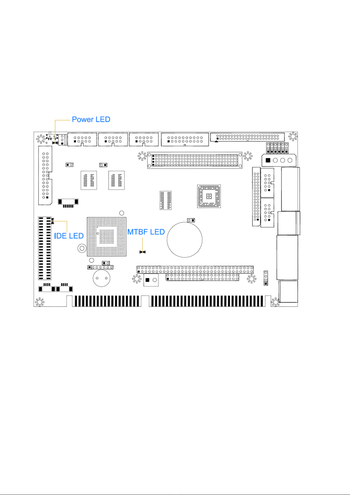
Jumpers & LEDs
Vortex86SX-6124-FD-V2 Vortex86SX™Half-SizeCPUModule 9
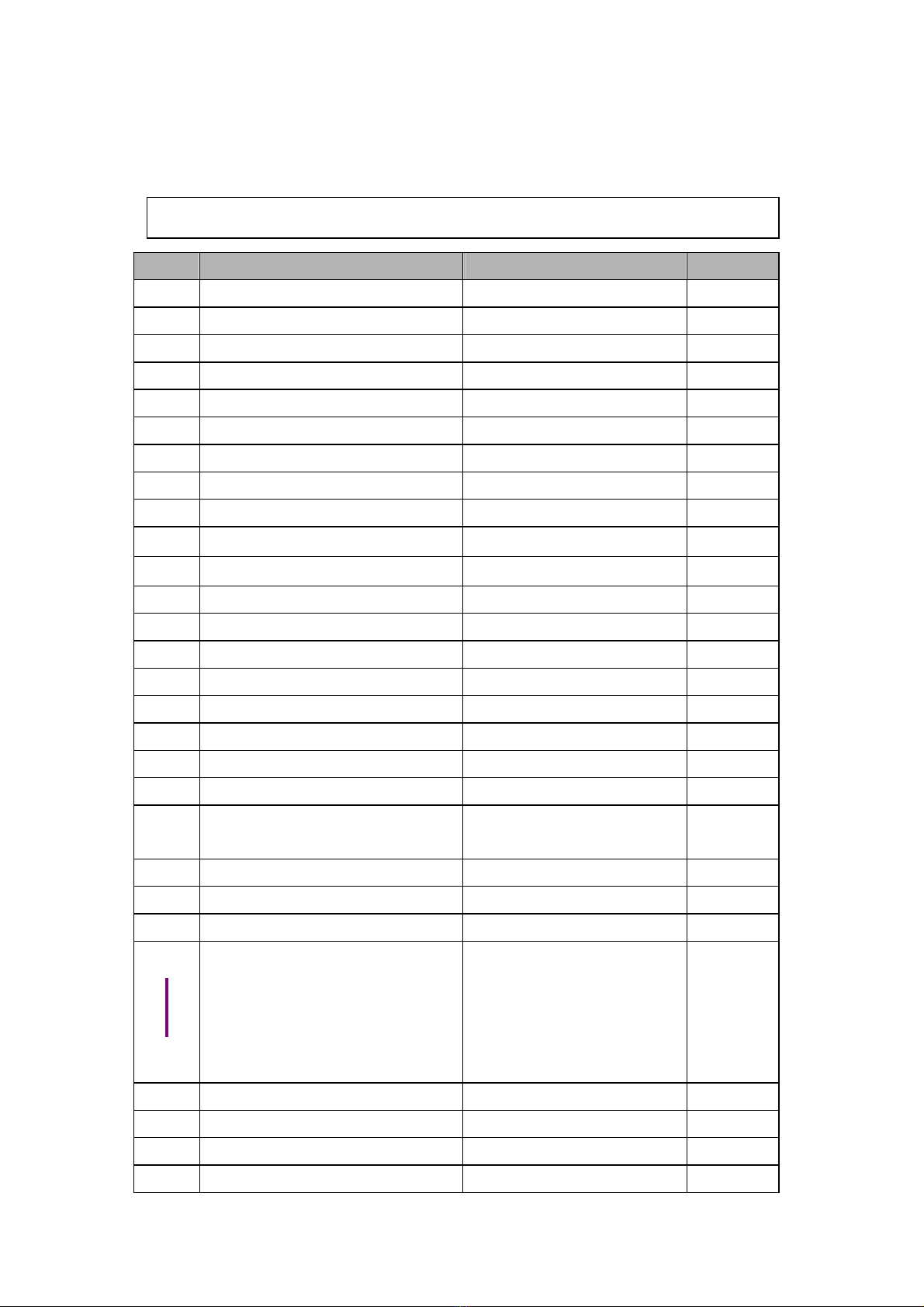
2.3 Connectors & Jumpers Summary
Summary Table
Nbr Description Type of Connections Pin nbrs.
J1 IDE Box Header, 2.0∅, 22x2 44-pin
J2 USB1 Box Header, 2.54∅, 5x2 10-pin
J3 USB2 Box Header, 2.54∅, 5x2 10-pin
J4 JTAG Wafer, 1.25∅, 6x1 6-pin
J5 Reset Pin Header, 2,54∅,1x2 2-pin
J6 Redundancy (Optional) Pin Header, 2.54∅, 7x1 7-pin
J7 System –Fail-Switch (Optional)
Pin Header, 2.54∅, 2x1 2-pin
J8 PS/2 Keyboard & Mouse Mini-Din Connector 6-pin
J9 COM1(TTL/GPIO-P4 ) D-Sub Connector 9-pin
J10 COM2(RS232/RS422/RS485) Box Header, 2.54∅5x2 10-pin
J11 GPIO ( Port 0 / 1) Box Header, 2.54∅,10x2 20-pin
J12 RS-485 Molex Header,2.54∅, 3x1 3-pin
J17 Power Connector Box Header, 5.0∅Molex 4-pin
J18 Power Connector Terminal Block 5.0∅,2x1 2-pin
J19 COM3 Box Header, 2.54∅, 5x2 10-pin
J20 PRINT Box Header, 2.54∅,13x2 26-pin
J21 COM4 Box Header, 2.54∅, 5x2 10-pin
J22 PC/104 Connector – 64 pin Box Header, 2.54∅32x2 64-pin
J24 PC/104 Connector – 40 pin Box Header, 2.54∅,20x2 40-pin
J26 4P Power Source (Interconnect
to PC/104 – J22) Pin Header, 2.54∅, 4x1 4-pin
J27 PC/104 + (Optional) Box Header, 2.0∅, 30x4 120-pin
J28 VGA D-Sub female connector 15-pin
J29 LCD Box Header,2.0∅,22x2 44-pin
J30
J35
Display type Setup Pin Header, 2.54∅, 3x1 3-pin
J36 10/100Base-TEthernet LAN RJ45 Connector 8-pin
J37 LINE-OUT (Optional) Wafer, 1.25∅, 4x1 4-pin
J38 MIC-IN (Optional) Wafer, 1.25∅, 4x1 4-pin
J39 JTAG Disable (Default setting)
Pin Header, 2,54∅,1x2 2-pin

Vortex86SX-6124-FD-V2 Vortex86SX™Half-SizeCPUModule 10
J40 Master/Slave for IDE & CF Slide Switch 3-pin
J41 Console Redirection (Optional)
Pin Header, 2,54∅,1x2 2-pin
J42 FDD Box Header, 2.0∅,17x2 34-pin
PWR-L
ED PowerActive LED (Red) LED-SMD
IDE-
LED IDEActive LED (Green ) LED-SMD
MTBF-
LED
MTBF-Out (Orange) LED-SMD
CF1 Compact Flash Type I/II CF Connector 50-pin
SP1 BUZZER

Vortex86SX-6124-FD-V2 Vortex86SX™Half-SizeCPUModule 11
2.4 Pin Assignments & Jumper Settings
J1: IDE (44 Pins)
J2: USB 1
Pin # Signal Name
Pin # Signal Name
1 VCC 2 VCC
3 LUSBD0- 4 LUSBD1-
5 LUSBD0+ 6 LUSBD1+
7 GND 8 GND
9 GGND 10 GGND
Pin # Signal Name
Pin # Signal Name
1 IDERST 2 GND
3 IDED7 4 IDED8
5 IDED6 6 IDED9
7 IDED5 8 IDED10
9 IDED4 10 IDED11
11 IDED3 12 IDED12
13 IDED2 14 IDED13
15 IDED1 16 IDED14
17 IDED0 18 IDED15
19 GND 20 NC
21 IDEREQ 22 GND
23 IDEIOW 24 GND
25 IDEIOR 26 GND
27 ICHRDY 28 GND
29 IDEACK 30 GND
31 IDEINT 32 NC
33 IDESA1 34 IDECBLID
35 IDESA0 36 IDESA2
37 IDECS-0 38 IDECS1
39 IDELED 40 GND
41 VCC 42 VCC
43 GND 44 NC

Vortex86SX-6124-FD-V2 Vortex86SX™Half-SizeCPUModule 12
J3: USB 2
Pin # Signal Name
Pin # Signal Name
1 VCC 2 VCC
3 LUSBD2- 4 LUSBD3-
5 LUSBD2+ 6 LUSBD3+
7 GND 8 GND
9 GGND 10 GGND
J4: JTAG (Default setting: off)
Pin # Signal Name
Pin # Signal Name
1 VCC 2 GND
3 TCK 4 TDO
5 TDI 6 TMS
J5: RESET
Pin # Signal Name
Pin # Signal Name
1 Reset 2 GND
J6: Redundancy (Optional)
Pin # Signal Name Pin # Signal Name
1 GND 2 SYS-FAIL-OUT
3 SYS-FAIL-IN 4 GPCS0
5 SYS-GPCS-IN 6 TXD9\
7 RXD9\
J7: System-Fail-Switch (Optional)
Pin # Signal Name
1 SYS-SW-IN
2 GND

Vortex86SX-6124-FD-V2 Vortex86SX™Half-SizeCPUModule 13
J8: PS/2 KBD / Mouse
Pin # Signal Name
Pin # Signal Name
1 KBCLK 2 MSCLK
3 GND 4 KBDAT
5 MSDAT 6 VCC
7 GND 8 GND
9 GND
J9: COM 1 (Optional: TTL/ GPIO-P4)
Pin # Signal
Name Pin # Signal
Name
1 DCD1 2 RXD1
3 TXD1 4 DTR1
5 GND 6 DSR1
7 RTS1 8 CTS1
9 RI1 10 GND
11 GND
J10: COM2 RS232 / RS422 / RS485 (Optional: TTL)
Pin # Signal Name Pin #
Signal Name
1 DCD2/ 422TX- / RS485- 2 RXD2 / 422TX+ / RS485+
3 TXD2 / 422RX+ 4 DTR2 / 422RX-
5 GND 6 DSR2
7 RTS2 8 CTS2
9 RI2 10 NC

Vortex86SX-6124-FD-V2 Vortex86SX™Half-SizeCPUModule 14
J11: GPIO (Port 0 / Port 1)
J12: RS485 (Auto direction)
J17: Power Connector – 4-pin Header (P4 Molex 5mm)
Pin # Signal
Name
1 +5V
2 GND
3 GND
4 +12V
Pin # Signal Name
Pin # Signal Name
1 GND 2 VCC
3 GP00 4 GP10
5 GP01 6 GP11
7 GP02 8 GP12
9 GP03 10 GP13
11 GP04 12 GP14
13 GP05 14 GP15
15 GP06 16 GP16
17 GP07 18 GP17
19 VCC 20 GND
Pin # Signal Name
1 RS485+
2 RS485-
3 GND

Vortex86SX-6124-FD-V2 Vortex86SX™Half-SizeCPUModule 15
J18: Power Connector (Terminal Block 5.0mm)
Pin # Signal Name
1 +5V
2 GND
J19: COM3 (Optional: TTL)
Pin # Signal Name
Pin # Signal Name
1 DCD3 2 RXD3
3 TXD3 4 DTR3
5 GND 6 DSR3
7 RTS3 8 CTS3
9 RI3 10 NC
J20: PRINT
Pin # Signal Name
Pin # Signal Name
1 STB- 14 AFD-
2 PD0 15 ERR-
3 PD1 16 INIT-
4 PD2 17 SLIN-
5 PD3 18 GND
6 PD4 19 GND
7 PD5 20 GND
8 PD6 21 GND
9 PD7 22 GND
10 ACK- 23 GND
11 BUSY 24 GND
12 PE 25 GND
13 SLCT 26 NC
J21: COM4 (Optional: TTL)
Pin # Signal Name
Pin # Signal Name
1 DCD4 2 RXD4
3 TXD4 4 DTR4
5 GND 6 DSR4
7 RTS4 8 CTS4
9 RI4 10 NC

Vortex86SX-6124-FD-V2 Vortex86SX™Half-SizeCPUModule 16
J22: PC/104 Connector – 64pin
Pin # Signal Name
Pin
# Signal Name
1 IOCHCHK *
2 GND
3 SD7 4 RESETDRV
5 SD6 6 VCC
7 SD5 8 IRQ9
9 SD4 10 -5V
11 SD3 12
DRQ2
13 SD2 14 -12V
15 SD1 16 OWS
17 SD0 18 +12V
19 IOCHRDY
20 GND
21 AEN 22 SMEMW *
23 SA19 24 SMEMR *
25 SA18 26 IOW *
27 SA17 28 IOR *
29 SA16 30 DACK3 *
31 SA15 32 DRQ3
33 SA14 34 DACK1 *
35 SA13 36 DRQ1
37 SA12 38 REFRESH *
39 SA11 40 SYSCLK
41 SA10 42 IRQ7
43 SA9 44 IRQ6
45 SA8 46 IRQ5
47 SA7 48 IRQ4
49 SA6 50 IRQ3
51 SA5 52 DACK2 *
53 SA4 54 TC
55 SA3 56 BALE
57 SA2 58 VCC
59 SA1 60 OSC
61 SA0 62 GND
63 GND 64 GND
Table of contents
Other EMAC Control Unit manuals


Popular Control Unit manuals by other brands


Honeywell
Honeywell HM700AFVALVE quick start guide

Duplomatic
Duplomatic DDC1-12-H Series installation manual

Littfinski Daten Technik
Littfinski Daten Technik Digital-Professional Series Assembly instruction

Hunter
Hunter Hydrawise WAND Setup guide

CSM
CSM HV BM 1.1 installation manual

Allen-Bradley
Allen-Bradley 193-DNENCAT user manual