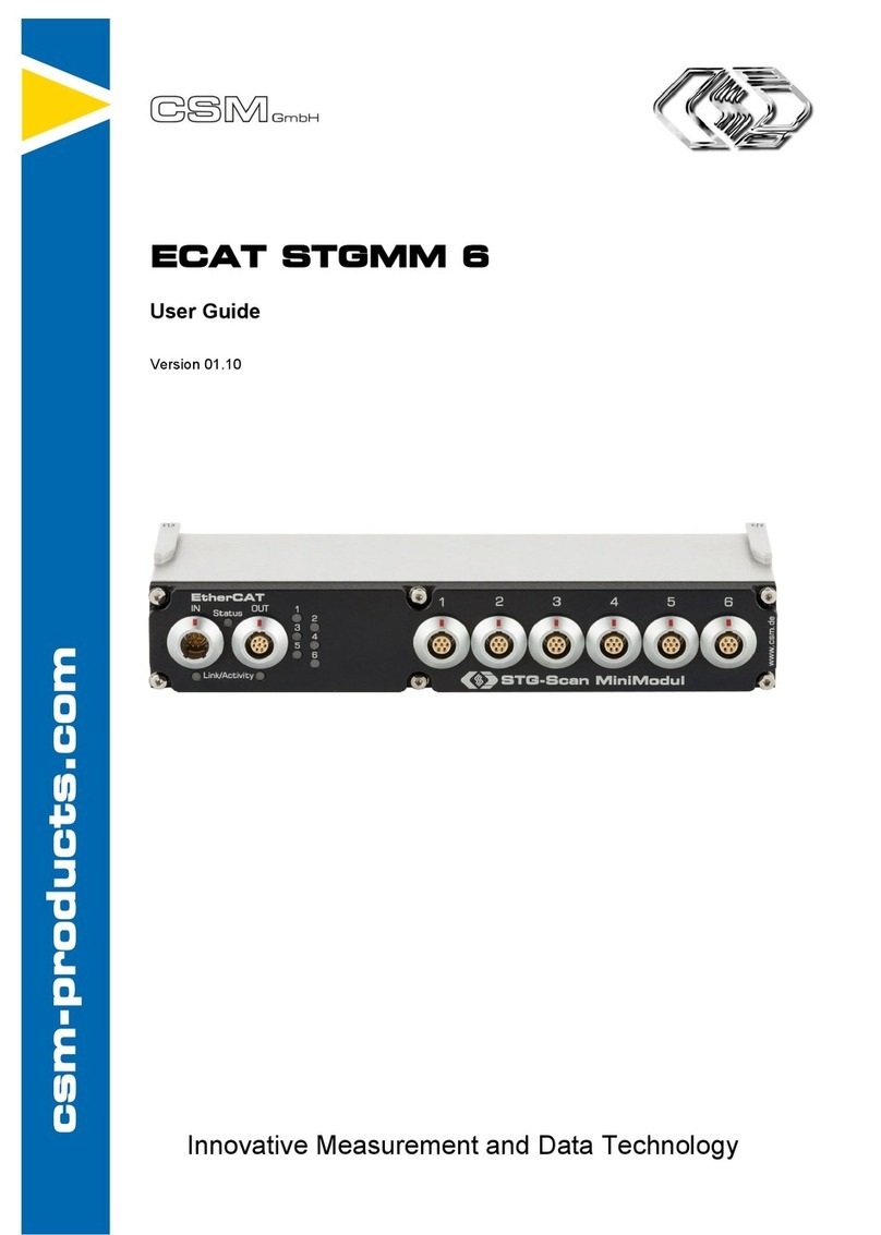
CSM HV BM 1.1 User manual

Innovative Measurement and Data Technology
HV Breakout Module
Type 1.1 | 1.2 | 3.1
Installation Manual Version 01.20

HV Breakout Module – Copyright
Installation Manual I Version . //
Copyright
All concepts and procedures introduced in this document are intellectual properties of
CSMGmbH.
Copying or usage by third parties without written permission of CSM GmbH is strictly prohibited.
This document is subject to change without notice!
Trademarks
All trademarks being mentioned in this document are properties of their respective owners.
EtherCAT® is a registered trademark and patented technology, licensed by
Beckhoff Automation GmbH, Germany.
Product disposal/recycling
When this symbol (crossed-out wheeled bin) appears on the device, this means that the
European Directive //EU applies to this device.
The correct disposal of old equipment will protect the environment and people from pos-
sible negative consequences.
Become familiar with local regulations for separate collection of electrical
and electronic equipment.
Follow local regulations and do not dispose of old equipment with house-
hold waste.
Contact Information
CSM offers support for its products during the entire product life cycle. Updates for the
individual components (e.g. documentation, configuration software and firmware) are made
available on the CSM website. To keep up to date, it is therefore recommended that you
check the download area of the CSM website for updates at least once a month.
Germany (Headquarters) USA
Address CSM Computer-Systeme-
Messtechnik GmbH CSM Products, Inc.
Raiffeisenstrasse
Filderstadt, Germany Opdyke Court, Suite
Auburn Hills, MI
Phone
E-mail info@csm.de info@csmproductsinc.com
Website www.csm.de www.csmproductsinc.com

Installation Manual II Version . //
HV Breakout Module – Contents
Contents
Introduction . . . . . . . . . . . . . . . . . . .
. Liability disclaimer . . . . . . . . . . . . . . .
. Warranty and exclusion of warranty . . . . . . . . .
. ESD information . . . . . . . . . . . . . . . .
Safety Instructions . . . . . . . . . . . . . . . . .
. General safety instructions . . . . . . . . . . .
. Obligations of the operator . . . . . . . . . . .
. Intended use . . . . . . . . . . . . . . . .
Product Description. . . . . . . . . . . . . . . . .
. Technical data overview. . . . . . . . . . . . .
. Connections and components. . . . . . . . . . .
. Functional description of LED indicators . . . . . . .
3.3.1 Status LED indicator for EtherCAT® bus. . . . . . . 8
3.3.2 CAN bus LED indicator . . . . . . . . . . . . 8
3.3.3 EtherCAT® bus LED indicators . . . . . . . . . . 9
3.3.4 Measurement channel LED indicators . . . . . . . 9
Mounting and installation . . . . . . . . . . . . . .
. Before mounting . . . . . . . . . . . . . . .
. Connecting HV power cables to HV BM devices . . . . .
4.3.1 HV BM 1.x: Connection diagrams . . . . . . . . .13
4.3.2 Preparing the PG gland . . . . . . . . . . . .14
4.3.3 Connecting the HV power cables . . . . . . . . . 15
4.3.3.1 Opening the housing . . . . . . . . . . . 16
4.3.3.2 Intermediate step: Sliding pressure screws and
springs on the HV power cable . . . . . . . . 16
4.3.3.3 HV BM 1.x: Connecting the HV power cables . . . .17
4.3.3.4 Exceptional case: Mounting ring terminals for
cable cross-section 35 mm² . . . . . . . . . 18
4.3.3.5 HV BM 3.1: Connecting the HV power cables . . . .20
4.3.3.6 Tighten the PG glands and close the housing . . . 21
. Installing HV Breakout Modules . . . . . . . . . .
4.4.1 Before installation . . . . . . . . . . . . . 22
4.4.2 Connectors . . . . . . . . . . . . . . . .23
4.4.2.1 CAN sockets . . . . . . . . . . . . . . 23
4.4.2.2 EtherCAT® IN socket. . . . . . . . . . . . 24
4.4.2.3 EtherCAT® OUT socket . . . . . . . . . . . 25
4.4.2.4 Ground connection . . . . . . . . . . . . 25

Installation Manual III Version . //
HV Breakout Module – Contents
How to use HV Breakout Modules . . . . . . . . . . . .
. Application example . . . . . . . . . . . . . .
. HV Breakout Module configuration . . . . . . . . .
5.2.1 Preparing configuration . . . . . . . . . . . . 29
5.2.2 Auto-Configuration . . . . . . . . . . . . . 29
.. Device configuration dialog . . . . . . . . . .
5.2.4 Channel Configuration Dialog . . . . . . . . . .31
5.2.5 Temperature monitoring . . . . . . . . . . . 33
5.2.6 Complete the configuration . . . . . . . . . . 33
5.2.6.1 Transferring configuration data
to the measurement module . . . . . . . . .33
5.2.6.2 Saving a configuration . . . . . . . . . . .34
5.2.6.3 Documenting a configuration. . . . . . . . . 34
Maintenance and Cleaning . . . . . . . . . . . . . .
. Type label . . . . . . . . . . . . . . . . .
. Shunt label . . . . . . . . . . . . . . . . .
. Maintenance services . . . . . . . . . . . . .
. Cleaning instructions. . . . . . . . . . . . . .
Appendix. . . . . . . . . . . . . . . . . . . . .
. Cable preparation . . . . . . . . . . . . . . .
7.1.2 Cable assembly for cross sections 35 mm² to 95mm² . .38
7.1.3 HV BM 1.1 connection example, cable cross-section
2x 6 mm². . . . . . . . . . . . . . . . . 41
. List of figures . . . . . . . . . . . . . . . .
. List of tables . . . . . . . . . . . . . . . .

HV Breakout Module – Introduction
Installation Manual Version . //
Introduction
. Liability disclaimer
fThis installation manual and further technical documents are part of the product and
contain important information for its safe and efficient use. To maintain the high quality
level the product is continuously being developed, which may result in the product's
technical details changing at short notice. As a result, the contents of this documentation
may differ from the technical specifications of the product. No claims against the manu-
facturer can therefore be derived from the contents of the product documentation.
fCSM GmbH is not liable for technical or editorial errors or missing information.
fCSM GmbH assumes no liability for damage resulting from improper use of the product
and/or non-observance of the product documentation, in particular the safety instructions.
→ See chapter "Safety Instructions".
. Warranty and exclusion of warranty
The warranty covers the safety and functionality of the product within the warranty period.
Excluded from the warranty are claims based on possible consequential damages caused by
malfunction or non-function of the product.
The warranty shall become invalid if:
fthe product is handled improperly,
fprescribed maintenance intervals are not observed,
fthe product is modified by the end-user,
fthe user does not observe the safety instructions and the product documentation,
f
the product is operated with accessories or parts which are not explicitly approved for
operation by the manufacturer of the product.
→ See chapter "Safety Instructions".
. ESD information
HV Breakout Modules have not yet been conclusively tested for conformity with the require-
ments of EU Directive //EU.

HV Breakout Module – Safety Instructions
Installation Manual Version . //
Safety Instructions
This chapter contains important safety information. Please read the following paragraphs
carefully.
. General safety instructions
WARNING!
HV Breakout Modules (HV BM) are used in high-voltage applications.
Improper handling of HV Breakout Modules may result in electrical
shocks which are dangerous to life.
)Use only qualified and trained personnel.
)Observe safety instructions.
WARNING!
The orange cover of the housing may be opened to mount or remove the
HV power cables.
)Before handling, especially before opening the cover, make sure that the
HV power cables have been disconnected.
)HV BM ./.: Fasten HV power cables only with the supplied or, alterna-
tively, suitable ring terminals and nuts.
)Observe the mounting instructions in this installation manual. It is parti-
cularly important that cover and PG glands are properly mounted in order
to ensure the tightness of the housing.
WARNING!
When using HV power cables made of aluminum and ring terminals made
of an electrochemically nobler metal (copper), the contact resistance
between the two components increases.
This can lead to a massive increase in temperature and in the worst case
to the development of fire.
" If ring terminals made of copper are used for connecting HVBreakout
Modules, make sure that only HV power cables made of copper are used.
HV power cables made of aluminum require a specific connection technique.
Please contact our technical support for further information.
WARNING!
The improper opening of the device housing impairs the operational safety
of the HV measurement module and entails the risk of life-threatening
electrical shocks.
)Open the housing only to connect the HV power cables and then close it
carefully.
)Do not carry out any mechanical or electrical modifications on the
HVmeasurement module.
)Do not replace the shunt module.
)Only operate the measurement module when the housing is closed.
HV Breakout Modules are not integrated into the interlock loop. When
the cover is open, there may be high-voltage on the exposed contacts.

HV Breakout Module – Safety Instructions
Installation Manual Version . //
WARNING!
The behavior of the CAN bus can be influenced by connecting a CAN bus
measurement module to an existing CAN bus system.
Improper use of a CAN bus system may cause life-threatening situations
and material damage.
" Always connect CAN bus measurement modules to a separate CAN bus
system (measurement bus).
" Make sure that this work is only carried out by qualified and trained
personnel.
Maximum internal temperature
Module version Hardware revision max. internal temperature
HV BM ./HV BM . A C
HV BM . B to D C
HV BM ./HV BM . as of E C
HV BM . as of A C
Tab. 2-1: Maximum internal temperature
WARNING!
The internal temperature of the measurement module must not be exceeded
(see Tab. -).
The shunt temperature must not exceed 120C. As soon as that value is
exceeded, the module will send the error value "0x001" instead of a measured
value until the temperature value drops below 115C again.
Exceeding the limit impairs the operational safety of the HV measurement
module and entails the risk of life-threatening electrical shocks.
)Switch off the power supply or interrupt the current flow through the
shunt to prevent further temperature increase of the module.
)
Always monitor the temperature of the shunt and the internal temperature
of the measurement module in order to make sure at any time that they
do not overheat.
→ See chapter .. "Temperature monitoring".
WARNING!
The measurement module has to be connected to ground in order to
ensure user safety.
If the ground connection is not established, there is danger to life due to
high voltage.
" Connect the measurement module to ground (PE).
" Make sure that this work is only carried out by qualified and trained
personnel.
" Observe safety instructions.
→ See chapter ... "Ground connection".

HV Breakout Module – Safety Instructions
Installation Manual Version . //
CAUTION!
The measurement module heats up considerably if it is
operated in a corresponding working environment (e.g.
engine compartment). The shunt also heats up consider-
ably during operation under high load. The surface and the
inside of the measurement module can therefore become
extremely hot.
A permanent measurement of high currents should be
avoided in order to prevent the internal temperature of
the module from exceeding the permissible range.
Touching the surface may cause serious burns.
)Let the measurement module cool down before handling,
especially before opening the orange-colored cover.
)Wear appropriate safety gloves, if required.
HNOTE!
i
The isolation barrier can be damaged due to aging, overvoltage, bipolar
voltage, high temperature and mechanical wear! In order to assure the
proper functioning and the electrical safety of the measuring module,
periodical tests of the reinforced insulation every months are requi-
red! If there is reason to assume that the isolation might be defective,
a test should be carried out immediately before putting the device in
operation again.
" Make sure that a high-voltage isolation test according to
EN-: is carried out at least every months.
" If there is reason to assume that the isolation barrier is defective,
a HV isolation test needs to be carried out immediately.
HNOTE!
i
The threaded mounting hole is designed to connect the housing to the
vehicle chassis or to protective ground (PA/PE) in a test bench.
" Do not use the threaded mounting hole for any other purpose,
e.g. for mounting the device.
→ See chapter ... "Ground connection".
NOTE NOTE!
i
Differences in potential between the measurement module ( shield of
the interface cable) and the mounting location can falsify measurement
results or destroy the measurement module.
" Make sure that no differences in potential occur when mounting the
device.
" Isolate the measurement module from the mounting location, if
required.
NOTE NOTE!
i
Trouble-free operation and electrical safety can only be ensured if the
measurement module is correctly installed.
" Make sure that the device is correctly installed.
" Operate the measurement module only within the specified opera-
ting environment.
→ See HV BM datasheets for further information.

HV Breakout Module – Safety Instructions
Installation Manual Version . //
. Obligations of the operator
fThe operator must ensure that only qualified and authorized personnel are entrusted with
handling the product. This applies to assembly, installation and operation.
fIn addition to the technical product documentation, the operator may have to provide
further operating instructions in compliance with the Act on Occupational Safety and Health.
. Intended use
fHV Breakout Module series measurement modules were developed for measuring volta-
ges and currents and may only be used for this purpose.
fThese measurement modules may only be used for the above-mentioned purpose and
under the operating conditions stated in the technical specifications.
→ See HV BM datasheets for further information.
fThe operational safety can only be ensured if the device is used in accordance with its
intended use.
fCompliance with the intended use also means that this user guide must be carefully read
and the instructions contained must be observed.
fInspection and repair work must only be carried out by CSM.
fThe operator is solely responsible if the measurement module is used in a way that does
not comply with its intended use.

HV Breakout Module – Product Description
Installation Manual Version . //
Product Description
. Technical data overview
HV Breakout Modules (HV BM) are specifically designed for safe measurements on cables
carrying high voltage. Current and voltage are measured and the instantaneous power is
calculated online in the module.
The voltage is measured directly. The current measurement is done by using a shunt module,
which contains a differential amplifier as well as a temperature sensor and memory for cali-
bration data for automatic online temperature compensation.
The HV BM outputs the measured data at a data rate of up to MHz via the EtherCAT®/ECAT
interface and at a data rate of up to kHz via the additional CAN interface at the same time.
This allows fast data acquisition via Ethernet with simultaneous data recording via a CAN data
logger.
The HV BM is integrated into the HV power cables by feeding the cables through PG glands
into the inside of the module and connecting them there.
CSM provides shunt modules with different measurement ranges for HV BM . and HVBM..
The shunt modules are selected individually and are permanently mounted.
→ See HV BM datasheets for further information.
Basic technical data
Designation HV BM . HV BM . HV BM .
Phases
Measurement
range (max.)
Nominal voltage V
Peak voltage V V
Nominal current A A A
Peak current A A A
Measurement
data rate (max.)
ECAT kHz kHz
CAN kHz kHz
Tab. 3-1: HV BM basic technical data

HV Breakout Module – Product Description
Installation Manual Version . //
. Connections and components
Fig. - shows the connections of an HV BM .. The module versions HV BM . and HV BM .
are equipped with only one PG gland ①on each side of the housing and they lack the holes
for the threaded bolts ⑩. As for the HV BM ., the connection sockets (CAN/EtherCAT®) are
also located on the opposite side. Otherwise these modules are identical to the HV BM ..
The LED indicators ⑦, ⑧, ⑨are located in the front panel of the module housing. Depending
on the module version, the sockets for CAN ②, EtherCAT® ③ and power supply ④are embed-
ded in the left or the right side of the housing.
⑤⑦⑧⑨
⑩
⑩ ⑪
⑫⑪
④
②
②
③
①
①
⑫⑫
⑥
Fig. 3-1: HV BM 1.2, front view
. PG glands
. CAN sockets (→ chapter 4.4.2.1 "CAN sockets")
. EtherCAT® IN socket (→ chapter 4.4.2.2 "EtherCAT® IN socket")
. EtherCAT® OUT socket (→ chapter 4.4.2.3 "EtherCAT® OUT socket")
. EtherCAT® bus status LED indicator (→ chapter 3.3.1 "Status LED indicator for EtherCAT® bus")
. CAN bus LED indicator (→ chapter 3.3.2 "CAN bus LED indicator")
. LED indicators for EtherCAT® bus (→ chapter 3.3.3 "EtherCAT® bus LED indicators")
. LED indicators for EtherCAT® measurement channels (→ chapter 3.3.4 "Measurement
channel LED indicators")
. LED indicators for CAN measurement channels (→ chapter 3.3.4 "Measurement channel
LED indicators")
. Holes for threaded bolts for fastening multiple HV BM to each other.
. GORE™ membrane venting grooves with corresponding sticker
. Contact surfaces for measuring the resistance of protective earth (PE) to cover
The positions of the contact surfaces vary depending on module type and hardware revision.

HV Breakout Module – Product Description
Installation Manual Version . //
The rear side of the housing provides:
fType label (→ chapter 6.1 "Type label")
fShunt label (→ chapter 6.2 "Shunt label")
f"Next calibration date" sticker
The "HV insulation test" sticker is attached to the top side of the housing.
On the lower side of the housing there are four M threaded holes for mounting screws.
There is an M or M threaded hole (depending on the hardware revision) for a ground cable
in the right (HV BM .x) or the left (HV BM .) section of the housing.
→ See chapter ... "Ground connection".
. Functional description of LED indicators
.. Status LED indicator for EtherCAT® bus
After the measurement module is switched on, the two-colored status LED (Fig. -, ⑤) is lit
red for approx. . seconds and then fades out.
LED Meaning
Color Status
green flashing Device is in status PRE-OPERATIONAL.
green flickering Device is in status SAFE-OPERATIONAL.
green continuously lit Device is in status OPERATIONAL.
red flashing Configuration error
red continuously lit Measurement module is switched on or the power supply
connection has been established but there is no Ethernet
communication.
green/red flashing Flashing new firmware.
Tab. 3-2: Status LED
.. CAN bus LED indicator
The LED indicator (Fig. -, ➁) between the two CAN sockets provides information on the
operating status of the measurement module.
LED Meaning
Color Status
–off
Measurement module not connected or power supply
switched off
green continuously lit Normal operation
red continuously lit
Measurement module is in idle mode, either because the
configuration software has stopped data acquisition (no
error), or because there is a CAN bus or configuration problem.
red flashing The measurement module has been selected via the
configuration software and is in idle mode.
green/red flashing Firmware download in progress
Tab. 3-3: CAN bus LED indicator
Status designations according to Beckhoff and EtherCAT® Technology Group EtherCAT® standard.

HV Breakout Module – Product Description
Installation Manual Version . //
.. EtherCAT® bus LED indicators
The LED indicators for the sockets IN and OUT (Fig. -, ⑦) are lit or are flashing if the measure-
ment module is electrically connected to an XCP-Gateway or if data is being transferred.
LED Meaning
Color Status
green continuously lit Ethernet connection to HV BM or to a further measurement
module has been established, no data transfer.
green flashing
Ethernet connection is active, i.e. data transfer is in progress
-off No measurement module or XCP-Gateway connected.
Tab. 3-4: LED indicators IN/OUT
.. Measurement channel LED indicators
The measurement channel LED indicators (Fig. -, ⑧and ⑨) provide information on the status
of the corresponding measurement channel and the sensor excitation. There are separate LED
indicators for access via CAN bus or EtherCAT® bus. The measurement channels are arranged
as follows (left to right):
. Voltage: voltage measurement status
. Current: current measurement status
. Power: power calculation status
After switching-on the HV Breakout Module, all measurement channel LED indicators are lit
red, indicating the start-up process of the module. Once the module has initialized itself
and no errors were detected, the LED indicators will fade out.
After self-initialization, the device checks the connected shunt module. Meanwhile the
measurement channel LED indicators of the current channels ("Current") are lit red. If the
shunt module is correctly detected, the measurement channel LED fades out again.
The measurement range has to be identically configured on both the ECAT and the CAN
side, otherwise the module side that was configured first will not send measurement values
but a specified error value. This is indicated on the module by measurement channel LED
indictors permanently lit in red.
LED Meaning
Color Status
–off
Measurement module not connected or power supply switched
off or normal operation
red continuously
lit
Error while detecting the shunt module ("Current"-LEDs)
The configurations stored in the measurement module on
the CAN or EtherCAT® side differ from each other (all three
LEDs of the corresponding side)
red flashing
red, off: disabled channel selected via configuration
software
red, off: measured value is out of the measurement range
green flashing
Channel selected via the configuration software (single LED)
Module selected via the configuration software
(all LEDs of the corresponding side)
Tab. 3-5: Measurement channel LED indicators

HV Breakout Module – Mounting and installation
Installation Manual Version . //
Mounting and installation
For trouble-free operation and a long product life, certain requirements for mounting and
installation must be taken into account.
. Before mounting
An HV Breakout Module is equipped with two
GORE™ membranes (Fig. -). These are needed
to regulate pressure and humidity. To ensure
fault-free operation of the device, never block,
clog, or insert anything into the ventilation
openings in the front side ①and the cover of
the housing ②. If this happens, condensate
will accumulate inside the housing and
damage the measurement module.
➁➀
Fig. 4-1: HV BM 1.2, section with ventilation openings
NOTE!
i
The GORE™ membranes are needed to regulate pressure and humidity.
"
Do not block the ventilation opening for the GORE™ membranes during
installation.
NOTE!
i
Trouble-free operation and electrical safety can only be ensured if the
measurement module is correctly installed.
" Ensure correct installation.
"
Operate the measurement module exclusively within the specified
operating environment.
→ See HV BM datasheets for further information.
. Mounting HV Breakout Module
CAUTION!
HV Breakout Modules can heat up very considerably when current flows
through them. This applies not only during operation, but also when no
measurements are to be taken, but the module is integrated in a loaded
circuit (e.g. when charging the vehicle battery).
" Divert the resulting power dissipation, e.g. by using suitable mounting
plates, which in turn are attached to the chassis. Heat-conducting
paste should be applied between HV BM and mounting plate, as well
as between mounting plate and chassis.
" Always monitor the temperature of the shunt and the internal tem-
perature of the measurement module in order to make sure at any
time that they do not overheat.
→ See chapter .. "Temperature monitoring".

HV Breakout Module – Mounting and installation
Installation Manual Version . //
NOTE!
i
Strong magnetic fields, such as those induced by permanent magnets,
may impair the trouble-free operation of the measurement module.
" Never attach the measurement module to a permanent magnet.
Requirements
fThe ventilation openings of the GORE™ membrane must not be blocked or clogged by
mounting at the intended position.
fSelect a mounting position that ensures the ventilation openings are not permanently
submerged in any liquid.
fThe mounting position must offer sufficient space to connect and disconnect the cables
without kinking or clamping them.
fAvoid mounting positions in which the modules are subjected to continuous strong vibra-
tions and/or shocks.
Parts/material required
ffour M screws
fa suitable screwdriver or wrench
Mounting the measurement module
" Fasten the measurement module at the mounting position.
i
Please contact our support for the appropriate drill hole diagrams.
NOTE!
i
Making mechanical modifications to the housing, such as by drilling
additional holes, can impair the function of the measurement module or
destroy it. Additionally this would invalidate the warranty.
" Never drill additional holes in the housing.
" Observe mounting instructions.
The thread depth in the module housing is mm. The screw length must be chosen according to the thickness of the mounting
material.

HV Breakout Module – Mounting and installation
Installation Manual Version . //
. Connecting HV power cables to HV BM devices
This chapter provides information on how to connect HV power cables to an HV BM and on
the preparation and handling of PG glands
i
Information on the preparation of the various HV power cables can be
found in the appendix of this document.
→ See chapter . "Cable preparation".
i
Section headings with module-specific content are preceded by the module
name, which indicates that non-applicable sections can be skipped.
Required tools
fAllen key, size .
fTwo wrenches, size SW (for M), SW (for M) and SW (for M)
fHV BM .x only: Ring wrench (deep cranked) or ratchet/socket wrench (w. deep nut),
size SW (M) or SW (M)
NOTE!
The space inside a housing is limited. This is in particular true for module
version HV BM .. Therefore, ring wrenches should be avoided for assembly
work if possible.
" Use the smallest possible socket wrench inserts for assembly.
HV BM .x: Connecting the HV power cables to the measurement module
WARNING!
HV BM .x devices are supplied with suitable ring terminals.
" Only use adequate ring terminals when mounting the HV power cables.
" If you want to use ring terminals other than those included in the
scope of delivery, make sure that
fsufficient space is provided in the housing, so that there is ade-
quate clearance between the ring terminals and the housing as
well as between the ring terminals.
fthe combination of ring terminal and nut will not extend over the
threaded bolts. Otherwise the distance between nut and housing
cover may be too small.
There is the risk of life-threatening electric shocks and short-circuits if
these instructions are not observed.
The HV power cables are connected to HV BM .x modules by means of ring terminals mounted
on threaded bolts.
If current and voltage are to be measured:
" Attach an M ring terminal (HV BM .)or an M ring terminal (HV BM .) to
both positive HV cables (HV).
" Attach M ring terminals to both negative HV cables (HV-).
If only current is to be measured:
" Use an M ring terminal.
" Please observe the connection diagrams in chapter ...
M is only used for HV BM ., hardware revision A. As of hardware revision E, only M is used.
See fn. .

HV Breakout Module – Mounting and installation
Installation Manual Version . //
.. HV BM .x: Connection diagrams
i
fThe red arrows indicate the technical (positive) direction of the current.
fThe blue arrow indicates the technical (positive) direction of the voltage.
fFor the wiring displayed, the technical current and, if measured, the
technical voltage are output with the correct polarity.
Current and voltage measurement
Fig. - shows the appropriate diagram if current and voltage are to be measured. The source
is located on the left, the consumer on the right.
The current is measured in the minus path in order to minimize disturbances of the current
measurement. The voltage is measured on the consumer side between plus and minus path.
Ⓐ
-
-
-
-
HV BM
Shunt
Ⓥ
Source
Consumer
IU
Fig. 4-2: HV BM 1.x, connection diagram for voltage and current measurement
Exclusive current measurement in the minus path
Fig. - shows the appropriate diagram if only current in the minus path is to be measured.
Ⓐ
-
-
HV BM
Shunt
⊗
I
Fig. 4-3: HV BM 1.x, connection diagram for current measurement in the minus path
Exclusive current measurement in the plus path
Fig. - shows the appropriate diagram if only current in the plus path is to be measured.
Ⓐ
-
HV BM
Shunt
⊗
I
Fig. 4-4: HV BM 1.x, connection diagram for current measurement in the plus path

HV Breakout Module – Mounting and installation
Installation Manual Version . //
HV BM .: Connecting the HV power cable to the module
As for the HV BM ., the HV power cables are connected to the module by using Phoenix
terminals. The cable cross-section may not exceed mm each. The stripping length is
mm. The wires can be fitted with wire end sleeves, but it is not absolutely necessary.
.. Preparing the PG gland
" Loosen the four pressure screws using an
adequate wrench and remove them from
the threads.
Some PG cable glands are equipped with a two-
component silicone sealing insert (blue) and a
removable inlet.
The sealing insert has a specific sealing area (cable
diameter) with and without inlet. This is marked
accordingly (in Fig. -: -mm and - mm).
" Remove the sealing insert and cut out the
inlet if required.
The following PG gland types are available:
CSM type / / /
CSM article number ART ART ART
Pflitsch designation bg ms tri /sc bg ms tri /sc bg ms tri /sc
Sealing range without
inlet – mm – mm – mm
Sealing range with inlet — – mm – mm
Connecting thread M M M
Wrench width SW SW SW
Tightening torquemax. Nm max. Nm max. Nm
Tab. 4-1: Technical data of the PG glands used
For tightening torques and further manufacturer information, see https://www.pflitsch.de/fileadmin/user_upload/Downloads/
Kataloge/Blueglobe_Katalog__web.pdf, p. .
Fig. 4-5: PG glands opened

HV Breakout Module – Mounting and installation
Installation Manual Version . //
.. Connecting the HV power cables
fMost of the figures in this section display the mounting of HV power cables to an
HVBM. using ring terminals. The removal of the cables is done in reverse order.
fThe connecting procedure for HV BM . and HV BM . devices is almost identical, except
for the detail. HV BM ., hardware revision A, is equipped with a green inner cover which
has to be removed or reinserted in an additional step. As of hardware revision E, this green
inner cover is integrated in the orange housing cover, which means that the additional step
is no longer required.
fAs for the HV BM ., the HV power cables are connected by means of Phoenix terminals.
→ Please see chapter . "Cable preparation" for further information on the assembly of
HVpower cables.
WARNING!
The improper opening of the housing during operation entails the risk of
life-threatening electrical shocks.
" Make sure that the HV power cables have been disconnected before
opening the cover.
WARNING!
When using HV power cables made of aluminum and ring terminals made
of an electrochemically nobler metal (copper), the contact resistance
between the two components increases.
This can lead to a massive increase in temperature and in the worst case
to the development of fire.
" If ring terminals made of copper are used for connecting HVBreakout
Modules, make sure that only HV power cables made of copper are used.
HV power cables made of aluminum require a specific connection technique.
Please contact our technical support for further information.
CAUTION!
The measurement module heats up considerably if it is operated in a cor-
responding working environment (e.g. engine compartment). The shunt also
heats up considerably during operation under high load. The surface and the
inside of the measurement module can therefore become extremely hot.
" Let the measurement module cool down before touching and removing
the cover.
" Always monitor the shunt temperature and the internal temperature
of the measurement module in order to make sure at any time that
they do not overheat.
→ See chapter .. "Temperature monitoring".

HV Breakout Module – Mounting and installation
Installation Manual Version . //
... Opening the housing
Fig. 4-6: HV BM 1.2, housing closed
↺↺↺↺
↺↺↺↺↺↺
↺↺
" Loosen the four or six Allen screws (↺) in the cover of the housing.
" Remove the orange-colored cover.
Fig. 4-7: HV BM 1.1, housing opened, inner cover inserted
" HV BM . (hardware revision A): Remove the green inner cover.
... Intermediate step: Sliding pressure screws and springs on the HV power cable
" If not already done, loosen and remove the pressure screws of the PG glands.
Fig. 4-8: PG gland front view (pressure screw and spring)
" Loosen and remove the pressure screw ①and remove the spring ② from the PGgland.
Fig. 4-9: Sliding pressure screws and springs onto the HV power cable
" Slide the pressure screw ①and the spring ② onto the HV power cable.
" Feed the HV power cable(s) through the PG gland(s) into the housing.
Depending on the hardware revision, details of the measurement modules shown in Fig. - to Fig. - may vary.
As of hardware revision E, this work step is no longer required, as the inner cover has been integrated into the housing cover.
②
①
②
①
This manual suits for next models
2
Table of contents
Other CSM Control Unit manuals
Popular Control Unit manuals by other brands

GatesAir
GatesAir Intraplex DA-191B Installation and operation manual
Texas Instruments
Texas Instruments TSW12QJ1600 user guide
Channel
Channel Actulux SVM 24V-5A quick start guide
Omnitron
Omnitron iConverter TM3 quick start guide
Conel
Conel CLEAR FILL installation instructions

Emerson
Emerson Spence K3 instruction manual
