EMAC PCM-5315 User manual

SubCompact Board PCM-5315
PCM-5315
AMD
® Geode
LX800/900 series Processors
RTL8139DL for 10/10 0Mbps
Type II CompactFlash
2 COM (Re v.A), 5 COM (Rev. B)
4 USB2.0, 1 IrDA
Type III Mini PCI
PCM-5315 Manual Rev.A + B 4th Ed.
November 2009

SubCompact Board PCM-5315
i
Copyright Notice
This document is copyrighted, 2009. All rights are reserved. The
original manufacturer reserves the right to make improvements
to the products described in this manual at any time without
notice.
No part of this manual may be reproduced, copied, translated,
or transmitted in any form or by any means without the prior
written permission of the original manufacturer. Information
provided in this manual is intended to be accurate and reliable.
However, the original manufacturer assumes no responsibility
for its use, or for any infringements upon the rights of third
parties that may result from its use.
The material in this document is for product information only
and is subject to change without notice. While reasonable
efforts have been made in the preparation of this document to
assure its accuracy, the manufacturer assumes no liabilities resulting
from errors or omissions in this document, or from the use of the
information contained herein.
The manufacturer reserves the right to make changes in the product
design without notice to its users.

SubCompact Board PCM-5315
ii
Acknowledgments
All other products’ name or trademarks are properties of their
respective owners.
Award is a trademark of Award Software International, Inc.
CompactFlash™ is a trademark of the Compact Flash
Association.
AMD, the AMD Arrow logo and combinations thereof are
trademarks of Advanced Micro Devices, Inc.
Microsoft Windows® is a registered trademark of Microsoft Corp.
ITE is a trademark of Integrated Technology Express, Inc.
IBM, PC/AT, PS/2, and VGA are trademarks of International
Business Machines Corporation.
SoundBlaster is a trademark of Creative Labs, Inc.
All other product names or trademarks are properties of their
respective owners.

SubCompact Board PCM-5315
iii
Packing List
Before you begin installing your card, please make sure that the
following materials have been shipped:
• 1 9681531501 Cable Kit for PCM-5315
1700060192 Keyboard & Mouse Cable
1709100201 USB Cable
1701440500 IDE Cable 3.5”
• 1 9657666600 Jumper Cap
• 1 Quick Installation Guide
• 1 CD-ROM for manual (in PDF format) and drivers
• 1 PCM-53 15
If any of these items should be missing or damaged, please
contact your distributor or sales representative immediately.

SubCompact Board PCM-5315
iv
Contents
Chapter 1 General Information
1.1 Introduction................................................................ 1-2
1.2 Features .................................................................... 1-3
1.3 Specifications ............................................................ 1-4
Chapter 2 Quick Installation Guide
2.1 Safety Precautions .................................................... 2-2
2.2 Connectors, Jumpers and Mechanical Drawings...... 2-3
2.3 List of Jumpers .......................................................... 2-9
2.4 List of Connectors ..................................................... 2-10
2.5 Setting Jumpers ........................................................ 2-12
2.6 AT/ATX Power Type Selection (JP1)........................ 2-13
2.7 CFD Master/ Slave Selection (JP2) .......................... 2-13
2.8 Clear CMOS (JP3) .................................................... 2-13
2.9 LCD Clock and LVDS Operating Voltage Selection (JP4)
......................................................................................... 2-13
2.10 COM Ports RI/+5V/+12V Selection (JP5) ............... 2-14
2.11 Inverter Voltage Connector (JP6)............................ 2-14
2.12 CFD Voltage Selection (JP7) (For Rev.B only)....... 2-14
2.13 IDE Hard Drive Connector (CN1)............................ 2-14
2.14 Floppy Connector (CN2) ......................................... 2-15
2.15 Parallel Port Connector (CN3) ................................ 2-16
2.16 Front Panel Connector (CN4) ................................. 2-17

SubCompact Board PCM-5315
v
2.17 USB Port #1 and Port #2 (CN5) .............................. 2-17
2.18 Digital I/O Connector (CN6).................................... 2-17
2.19 Audio Input/Output/Cdin/MIC (CN7)........................ 2-18
2.20 ATX External 5VSB (CN8) ...................................... 2-18
2.21 4P Power Socket (CN9) .......................................... 2-19
2.22 LVDS Connector (CN10)......................................... 2-19
2.23 PC/104 (CN11) (For Rev.A only) ............................ 2-20
2.24 TTL LCD (CN12) ..................................................... 2-22
2.25 Serial Port #2 (CN13).............................................. 2-24
2.26 Fan Connector (CN14)............................................ 2-24
2.27 Ethernet 10/100Base-TX RJ-45 Phone Jack #1 (CN15)
......................................................................................... 2-25
2.28 Ethernet 10/100Base-TX RJ-45 Phone Jack #2 (CN16)
......................................................................................... 2-25
2.29 IrDA Connector (CN17)........................................... 2-25
2.30 Mini-DIN PS/2 Keyboard/Mouse Connector (CN18)2-26
2.31 Serial Port #1 Connector (CN19) ............................ 2-26
2.32 CRT Display Connector (CN20).............................. 2-26
2.33 USB Port #3 and Port #4 (CN21) ............................ 2-27
2.34 Inverter Voltage (CN22) ........................................ 2-27
2.35 Serial Port #3 (CN23)(For Rev.B only).................... 2-27
2.36 Serial Port #5 (CN24)(For Rev.B only).................... 2-28
2.37 Serial Port #4 (CN25)(For Rev.B only).................... 2-28
2.38 Serial Port #6 (CN26) (TTL/GPS) (For Rev.B only) 2-28
2.39 External Battery (BAT1) ........................................ 2-29

SubCompact Board PCM-5315
vi
2.40 Compact Flash Disk Slot (CFD1) .......................... 2-29
2.41 Mini-PCI Slot (MPCI1) ........................................... 2-30
2.42 DDR SODIMM Slot (DIMM1) ................................. 2-30
Chapter 3 Award BIOS Setup
3.1 System Test and Initialization. .................................. 3-2
3.2 Award BIOS Setup .................................................... 3-3
Chapter 4 Driver Installation
4.1 Software Drivers........................................................ 4-2
4.2 Necessary to know .................................................... 4-3
4.3 Installing VGA Driver................................................. 4-4
4.4 Installing AES Driver ................................................. 4-5
4.5 Installing PCI to ISA Bridge Driver ............................ 4-6
4.6 Installing Ethernet Driver........................................... 4-7
4.7 Ethernet Software Configuration............................... 4-7
4.8 Installing Audio Driver ............................................... 4-8
Appendix A Programming The Watchdog Timer
A.1 Programming .........................................................A-2
A.2 ITE8712 Watchdog Timer Initial Program..............A-5
Appendix B I/O Information
B.1 I/O Address Map ....................................................B-2
B.2 1st MB Memory Address Map ................................B-2
B.3 IRQ Mapping Chart for Rev. A...............................B-3
B.4 IRQ Mapping Chart for Rev. B...............................B-3

SubCompact Board PCM-5315
vii
B.5 DMA Channel Assignments...................................B-3
Appendix C Mating Connector
C.1 List of Mating Connectors and Cables.................. C-2

SubCompact Board PCM-5315
Chapter 1 General Information 1- 1
General
Chapter
1
Information

SubCompact Board PCM-5315
Chapter 1 General Information 1- 2
1.1 Introduction
Announcing the debut of the new generation 3.5” SubCompact
Board—PCM-5315. The PCM-5315 not only completes
this product line of Subcompact boards, but also balances
performance and cost in the embedded market.
PCM-5315 adopts optional onboard AMD Geode LX800 and
LX900. The system memory is deployed with SODIMM DDR
333/400 up to 1GB. In addition, Realtek RTL8139DL supports
two 10/100Base-TX that allows network connections. This
model applies a Type III Mini PCI socket for expansion.
Moreover, four USB 2.0, IDE, RS-232, RS-232/422/485 and
parallel ports are configured on the PCM-5315. Full functions
make PCM-5315 user friendly. With the PCM-5315, there are
no more worries about installing many necessary devices to
complete the functions of your system.
The display of PCM-5315 supports CRT/LCD simultaneous
display and is up to 24-bit single channel TTL/LVDS TFT LCD.
These great features fit into the needs of digital signage.
Furthermore, this brand new SubCompact board is developed to
cater to the requirements of Automation, Medical, ticket machine,
transportation, gaming, KIOSK, and POS/POI applications.

SubCompact Board PCM-5315
Chapter 1 General Information 1 - 3
1.2 Features
Onboard AMD Geode LX 800/LX900 processors
SODIMM DDR 333 Max. 1GB, DDR 400 Max. 512MB
Up to 24-bit Single Channel LVDS TFT LCD
Dual 10/100Mbps Ethernet
Type III Mini-PCI and PC/104 (For Rev.A Only) Expansions
IDE, Floppy Disk Drive & Compactflash Slot
AC97 Codec 2 CH Audio
COM, Parallel x 1, USB2.0 x 4, 8-bit Digital I/O, IrDA
+5V Only Operation

SubCompact Board PCM-5315
Chapter 1 General Information 1- 4
1.3 Specifications
System
Processor Onboard AMD Geode LX800/ LX900
Series Processor
System Memory 200-pin DDR SODIMM x 1,
Max. 1GB for DDR333 and 512MB
for DDR 400
Chipset AMD LX series + CS5536
I/O Chipset ITE IT8712+ IT8888G
Ethernet Realtek RTL8139DL, 10/100Mbps,
RJ-45 x 2
BIOS Award Plug & Play BIOS – 1MB
ROM
Watchdog Timer Generates a time-out system
reset
H/W Monitor Chipset Supports power supply voltages
and temperature monitoring
Expansion Interface PC/104 x 1 (For Rev.A only),
Mini PCI x 1
Power Requirement +5V/AT/ATX
Board Size 5.75”(L) x 4”(W) (146mm x 101.6mm)
Operating Temperature 32°F~ 140°F (0°C ~ 60°C)
-4°F~ 158°F (-20°C~70°C) (for
PCM-5315W only)

SubCompact Board PCM-5315
Chapter 1 General Information 1 - 5
Display Supports CRT/LCD simultaneous display
Chipset AMD LX series + TI SN75LVDS83
Memory Shared system memory up to 254 MB
LCD Interface Up to 24-bit TTL/LVDS TFT LCD
Resolution Up to 1920 x 1440 @ 24bpp for CRT
Up to 1600 x 1200 @ 24bpp for LCD
I/O
Storage EIDE x 1 (UDMA-33 x 1); Floppy Disk
Drive x 1; Type II CompactFlash x 1
Serial Port RS-232 x 1 (Rev.A)/ RS-232 x 4 &
TTL UART x 1 (Rev.B),
RS-232/422/485 x 1
Parallel Port SPP/EPP/ECP mode
USB Port USB2.0 x 4
PS/2 Port Keyboard & Mouse x 1
Digital I/O Supports 8-bit (Programmable)
IrDA One IrDA Tx/Rx header
Audio Realtek ALC203 2CH AC97 Codec,
MIC-in/ Line-in/ Line-out/ CD-in
SubCompact Board PCM-5315
Chapter 2 Quick Installation Guide 2-1
Quick
Installation
Chapter
2
Guide
Notice:
The Quick Installation Guide is derive
d
f
rom Chapter 2 of user manual. For othe
r
chapters and further installation
instructions, please refer to the use
r
manual CD-ROM that came with th
e
p
roduct.
Part No. 2007531522 Printed in Taiwan November 2008
SubCompact Board PCM-5315
Chapter 2 Quick Installation Guide 2 - 2
2.1 Safety Precautions
Always completely disconnect the power cord
from your board whenever you are working on
it. Do not make connections while the power is
on, because a sudden rush of power can
damage sensitive electronic components.
Always ground yourself to remove any static
charge before touching the board. Modern
electronic devices are very sensitive to static
electric charges. Use a grounding wrist strap at
all times. Place all electronic components on a
static-dissipative surface or in a static-shielded
bag when they are not in the chassis

SubCompact Board PCM-5315
Chapter2QuickInstallationGuide2 - 3
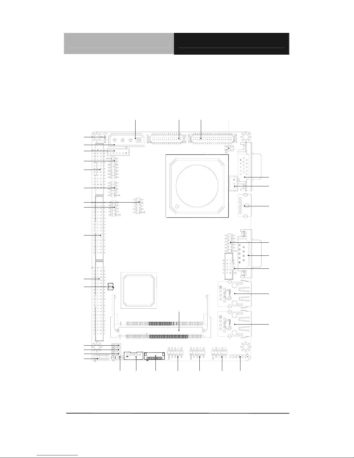
2.2 Jumpers, Connectors, and Mechanical Drawings
PCM-5315 Rev.A
Component Side
CN7
CN3
CN6
CN5
CN2
CN8
CN1
CN11
CN4
CN10
JP4
CN14
CN20
CN18
JP5
CN19
CN13
CN16
CN15
CN17
CN9
MPCI1
JP3
BAT1
CN22
JP2
JP6
CN12
JP1
CN21

SubCompact Board PCM-5315
Chapter 2 Quick Installation Guide 2 - 4
Solder Side
DIMM1
CFD1
0.00
0.00
30.49
12.43
52.59
34.84
132.84
66.04
SubCompact Board PCM-5315
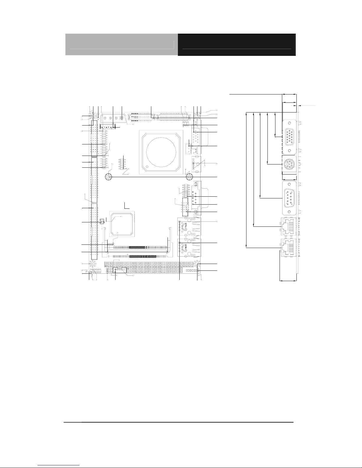
Chapter2QuickInstallationGuide2 - 5
Mechanical Drawings
0.00
0.00
8.89
3.22
7.35
1.19
50.46
92.07
125.56
0.63
133.93
0.00
18.67
123.73
108.27
97.98
5.13
132.56 132.27
85.76
95.20
133.93
98.38
137.16
119.27
106.68
91.93
91.07
91.73
53.95
61.13
47.18
85.33
86.12
78.73
88.21
38.11
19.06
79.15
0.00
6.10
96.14
14.55
(1.60)
(12.55)
(13.00)
(15.35)
(22.22)
(46.99)
(77.67)
(103.50)
(122.55)
8.42
37.73
11.41
9.42
120.27
53.28
82.66
87.14
125.81
86.17
27.87
17.40
18.84
12.39
38.31
50.09
29.17
0.60
13.44
20.71
7.24
4.70
5.14
95.20
26.62
131.95
87.67
HEATSINK HEIGHT (13.20)
10.77
13.34
68.34
SubCompact Board PCM-5315
Chapter 2 Quick Installation Guide 2 - 6 PCM
PCM-5315 Rev.B
Component Side
CN6
JP5
CN16
MPCI1
CN3
CN8
CN9
CN5
CN7
CN2
CN1
BAT1
JP3
JP2
JP7
CN4
CN21
JP1
JP6
CN22
CN26
CN24
CN25
CN23
CN17
CN15
CN13
CN19
CN18
CN14
CN20
CN10
CN9
CN12
JP4

SubCompact Board PCM-5315
Chapter2QuickInstallationGuide2 - 7
Solder Side
DIMM1
CFD1
8.89
98.38
30.49
12.43
52.53
34.84
132.84
66.04
0.00
0.00
Table of contents
Other EMAC Motherboard manuals

EMAC
EMAC iPac HCS12 User manual

EMAC
EMAC MicroPac 535 Quick user guide

EMAC
EMAC PCA-6782 User manual

EMAC
EMAC PCM-4896 User manual

EMAC
EMAC SBC-557 User manual

EMAC
EMAC PCM-4896L User manual

EMAC
EMAC SoM-iMX6U User manual

EMAC
EMAC PCM-53E52 User manual

EMAC
EMAC SBC-675 User manual

EMAC
EMAC PCM-6892E User manual


Popular Motherboard manuals by other brands

NXP Semiconductors
NXP Semiconductors TWR-K70F120M quick start guide

Commell
Commell LE-379 user manual

Honeywell
Honeywell Gamewell FCI ILI-MB-E3 Product installation document

Avalue Technology
Avalue Technology EMX-PNVB user manual

Merit
Merit Full MAXX Removal and installation

Advantech
Advantech PCM-3362Z Startup manual


