EMAC PCM-9580F-00A1 User manual

i
PCM-9580
Socket 478 Pentium IV SBC with
VGA, LVDS, Ethernet, Audio, &
USB 2.0
Users’ Manual

PCM-9580 User’s Manual ii
Copyright
This document is copyrighted, © 2003. All rights are reserved. The orig-
inal manufacturer reserves the right to make improvements to the prod-
ucts described in this manual at any time without notice.
No part of this manual may be reproduced, copied, translated or transmit-
ted in any form or by any means without the prior written permission of
the original manufacturer. Information provided in this manual is
intended to be accurate and reliable. However, the original manufacturer
assumes no responsibility for its use, nor for any infringements upon the
rights of third parties that may result from such use.
Acknowledgements
Award is a trademark of Award Software International, Inc.
VIA is a trademark of VIA Technologies, Inc.
IBM, PC/AT, PS/2 and VGA are trademarks of International Business
Machines Corporation.
Intel and Pentium are trademarks of Intel Corporation.
Microsoft Windows® is a registered trademark of Microsoft Corp.
RTL is a trademark of Realtek Semi-Conductor Co., Ltd.
ESS is a trademark of ESS Technology, Inc.
UMC is a trademark of United Microelectronics Corporation.
SMI is a trademark of Silicon Motion, Inc.
Creative is a trademark of Creative Technology LTD.
CHRONTEL is a trademark of Chrontel Inc.
All other product names or trademarks are properties of their respective
owners.
For more information on this and our other products, please visit
our website at: http://www.emacinc.com
For technical support and service, please visit our support website at:
http://www.emacinc.com/support
This manual is for the PCM-9580.
Part No. 2006958013
4th Edition, Printed May 2004

iii
Packing List
Before you begin installing your card, please make sure that the following
materials have been shipped:
• 1 PCM-9580 all-in-one single board computer
• 1 CD disk for utility and drivers
• 1 startup manual
• 1 Mini Jumper*10 PCS Package (p/n: 9689000002)
If any of these items are missing or damaged, contact your distributor or
sales representative immediately.
Model No. List Description
PCM-9580F-00A1 W/ 100 BASE-T Ethernet
PCM-9580FG-00A1 W/ 1000 BASE-T Ethernet
Caution!
Achtung!
Possible danger of explosion if batteries (if any)
are incorrectly replaced.
Replace only with the same or equivalent type
recommended by the manufacturer.
Dispose of used batteries (if any) according to
the manufacturer's instructions.

PCM-9580 User’s Manual iv
Additional Information and Assistance
1. Visit the distributator web site at www.emacinc.com where you can
find the latest information about the product.
2. Contact your distributor, sales representative, or customer service
center for technical support if you need additional assistance.
Please have the following information ready before you call:
• Product name and serial number
• Description of your peripheral attachments
• Description of your software (operating system, version, application
software, etc.)
• A complete description of the problem
• The exact wording of any error messages

v Table of Contents
Contents
Chapter 1 Introduction ......................................................2
1.1 Introduction ....................................................................... 2
1.1 Highly integrated multimedia SBC................................. 2
1.2 Features ............................................................................. 3
1.3 Specifications .................................................................... 3
1.4 Board layout: dimensions.................................................. 6
Figure 1.1:Board layout: dimensions.............................. 6
Chapter 2 Installation ........................................................8
2.1 Jumpers.............................................................................. 8
Table 2.1:Jumpers........................................................... 8
2.2 Connectors......................................................................... 9
Table 2.2:Connectors ...................................................... 9
2.3 Locating jumpers and Connectors................................... 10
Figure 2.1:Jumper & Connector (component side) ...... 10
2.4 Setting Jumpers ............................................................... 11
2.5 Clear CMOS (SW1) ........................................................ 12
2.6 Installing DIMMs............................................................ 12
2.7 IDE, CDROM hard drive connector (CN15, CN13)....... 13
2.7.1 Connecting the hard drive............................................. 13
2.8 Solid State Disk............................................................... 13
2.8.1 CompactFlash (CN29) .................................................. 13
2.9 Floppy drive connector (CN12) ...................................... 14
2.9.1 Connecting the floppy drive ......................................... 14
2.10 Parallel port connector (CN11) ....................................... 15
2.11 Keyboard and PS/2 mouse connector (CN17) ................ 15
2.12 Front Panel Connector (CN14) ....................................... 15
2.12.1 Power & HDD LED (pin 1-4 of CN14)........................ 15
2.12.2 Reset switch (pin 13-14 of CN14) ................................ 15
2.13 Power connectors (CN7, CN9, FAN1)............................ 16
2.13.1 ATX power connector, +3.3V, +5V, +12V (CN8)..... 16
2.13.2 ATX power connector, +12 V (CN10) ........................ 16
2.13.3 CPU Fan power supply connector (FAN1)................... 16
2.14 ATX power ON/OFF switch con. pin 11-12 of CN14.... 16
2.14.1 ATX feature (CN10) & soft power switch (CN14) ...... 16
2.15 Audio PC-97 Link interfaces (CN13) ............................. 16
2.15.1 PCM-231AV................................................................. 17
2.15.2 CD audio input connector (CN3 on the PCM-231AV) 17
2.16 COM port connector (CN9) ............................................ 17
2.17 VGA/LVDS interface connections.................................. 17

PCM-9580 User’s Manual vi
2.17.1 CRT display connector (CN9) ...................................... 17
2.17.2 LVDS LCD panel connector (CN5) ............................. 17
2.17.3 Panel type selection (S1)............................................... 18
2.18 TV-out interface (optional) (CN20) ................................ 18
2.19 Ethernet configuration..................................................... 18
2.19.1 100Base-T connector (CN3, PCM-9580F)................... 19
2.19.2 1000Base-T connector (CN8, PCM-9580FG).............. 19
2.19.3 Network boot ................................................................ 19
2.19.4 LAN controller power select (JP7) ............................... 19
2.20 Watchdog timer configuration ........................................ 20
2.20.1 Watchdog timer action (JP5) ........................................ 20
Table 2.4:Watchdog timer action (JP5) ........................ 20
2.21 USB connectors (CN1, CN23)........................................ 20
2.21.1 Embedded USB interface: ............................................ 21
Table 2.5:Embedded USB Pin Assignment.................. 22
Figure 2.2:Embedded USB Mod. Type I...................... 23
Figure 2.3:Embedded USB Type II/III Form Factor .... 24
Chapter 3 Software Configuration .................................26
3.1 Introduction ..................................................................... 26
3.2 Connections to Three Standard LCDs............................. 26
3.2.1 LG LM150X06 (1024 x 768 LVDS TFT LCD) ........... 26
Table 3.1:Connections to Toshiba LTM10C209A ....... 26
Chapter 4 Award BIOS Setup.........................................30
4.1 System test and initialization........................................... 30
4.1.1 System configuration verification................................. 30
4.2 Award BIOS setup .......................................................... 31
4.2.1 Entering setup .............................................................. 31
Figure 4.1:BIOS setup program initial screen .............. 31
4.2.2 Standard CMOS Features setup.................................... 32
Figure 4.2:CMOS Features setup.................................. 32
4.2.3 Advanced BIOS Features setup .................................... 33
Figure 4.3:Advanced BIOS Features setup................... 33
4.2.4 Advanced Chipset Features setup ................................. 34
Figure 4.4:Advanced Chipset Features setup ............... 34
4.2.5 Integrated Peripherals ................................................... 34
Figure 4.5:Integrated Peripherals.................................. 34
4.2.6 Power Management Setup ............................................ 35
Figure 4.6:Power Management Setup........................... 35
4.2.7 PnP/PCI Configurations................................................ 35
Figure 4.7:PnP/PCI Configurations .............................. 35
4.2.8 PC Health Status ........................................................... 36
Figure 4.8:PC Health Status.......................................... 36
4.2.9 Frequency/Voltage Control........................................... 37
Figure 4.9:Frequency/Voltage Control ......................... 37

vii Table of Contents
4.2.10 Load Optimized Defaults.............................................. 38
4.2.11 Set Password ................................................................. 38
4.2.12 Save & Exit Setup......................................................... 39
4.2.13 Exit Without Saving...................................................... 39
Chapter 5 PCI SVGA Setup ............................................42
5.1 Introduction ..................................................................... 42
5.1.1 Chipset .......................................................................... 42
5.1.2 Display memory............................................................ 42
5.1.3 Display types................................................................. 42
5.1.4 Dual/Simultaneous Display .......................................... 43
Figure 5.1:Selecting Display Settings........................... 43
5.2 Installation of the SVGA Driver ..................................... 44
5.2.1 Installation for Windows 98/2000/XP .......................... 44
5.2.2 Installation for Windows 98/Me ................................... 48
5.2.3 Installation for Windows NT ........................................ 53
5.2.4 Installation for Windows 2000 ..................................... 58
5.2.5 Installation for Windows XP ........................................ 63
5.3 Further Information ......................................................... 69
Chapter 6 Audio Setup.....................................................72
6.1 Introduction ..................................................................... 72
6.2 Driver installation............................................................ 72
6.2.1 Before you begin........................................................... 72
Chapter 7 PCI Bus Ethernet Interface...........................80
7.1 Introduction ..................................................................... 80
7.2 Features ........................................................................... 80
7.3 Installation of Ethernet Driver......................................... 80
7.3.1 Installation for Windows 2000 ..................................... 81
7.3.2 Installation for Windows NT ........................................ 85
7.4 Further information ......................................................... 91
Appendix A Programming the Watchdog Timer .............94
A.1 Supported Input Timing Modes ...................................... 94
Appendix B Pin Assignments .............................................98
B.1 CPU Fan Power Connector (FAN 1)............................... 98
B.2 Ethernet 10/100Base-T Connector (CN25)..................... 98
B.3 Ethernet 10/100/1000 BASE-T connector (CN26) ......... 99
B.4 Ethernet LED connector................................................ 100
B.5 ACLink audio connector (CN4).................................... 100
B.6 ATX Main Power Connector (CN6) ............................. 101
B.7 ATX 12V power connector (CN10).............................. 101
B.14 Embedded USB Connector (CN23) .............................. 107
B.21 GPIO Connector (CN16)............................................... 113

PCM-9580 User’s Manual viii
Appendix C System Assignments ....................................116
C.1 System I/O Ports............................................................ 116
Table C.1:System I/O Ports ........................................ 116
C.2 1st MB memory map..................................................... 117
Table C.2:1st MB memory map ................................. 117
C.3 DMA channel assignments............................................ 117
Table C.3:DMA channel assignments ........................ 117
C.4 Interrupt assignments .................................................... 118
Table C.4:Interrupt assignments ................................. 118
Appendix D Optional Extras ............................................120
D.1 PCM-10586-6000 Cable kit for PCM-9580F............... 120
D.2 PCM-10586-6G00 Cable kit for PCM-9580FG-00A1. 121
D.3 Optional USB cable (CN1 or CN23)............................. 121
D.4 ATX Power Control Cable (CN10)............................... 122
Appendix E Mechanical Drawings...................................124

1 Chapter1
CHAPTER
1
General Information
This chapter gives background
information on the PCM-9580.
Sections include:
• Introduction
• Features
• Specifications
• Board layout and dimensions

PCM-9580 User’s Manual 2
Chapter 1 Introduction
1.1 Introduction
The PCM-9580 is a Socket 478 Pentium IV single board computer (SBC)
with Gigabit, USB 2.0, 2channel 48-bit LVDS, audio controller, a 4X
AGP SVGA controller, one PCI slot and TV-out function. It supports
Pentium IV up to 3.06 GHz. The PCM-9580’s design is based on the
5.25" form factor that provides support for PCI module expansion. The
5.25" form factor also provides a convenient connector layout for easy
assembly, more efficient cable connections and better overall embedded
system integration. This compact (only 5.75” x 8”) unit offers all the
functions of a single board industrial computer, but still fits in the space
of a 5.25” CD-ROM drive.
On-board features include, four serial ports, one multi-mode parallel
(ECP/EPP/SPP) port, 4 USB (Universal Serial Bus) 1.1/2.0 ports, an
optional floppy drive controller, and a keyboard/PS/2 mouse interface.
The built-in high-speed PCI IDE controller supports both PIO and
UDMA/100 bus master modes. Up to four IDE devices can be con-
nected, including large hard disks, CD-ROM drives, and tape backup
drives.
The PCM-9580 features power management to minimize power con-
sumption. It complies with the “Green Function” standard and supports
Doze, Standby and Suspend modes. In addition, the board‘s watchdog
timer can automatically reset the system or generate an interrupt if the
system stops due to a program bug or EMI.
Highly integrated multimedia SBC
The PCM-9580 is a highly integrated multimedia SBC that combines
audio, video, and network functions on a single computer board the size
of a 5.25" CD-ROM drive. It provides an AC-97 interface and supports
Line-in,Line-out, and MIC-in via Optional PCM-232 audio module, and
up to 1600 x 1200 resolution @ 16.8 M colors with 8 to 64MB frame
buffer with system memory. Major on-board devices adopt PCI technol-
ogy, to achieve outstanding computing performance when used with
Intel® Pentium®IV processors. The PCM-9580 also supports an TV-out
for NTSC/PAL multimedia applications.

3 Chapter1
1.2 Features
• Socket 478 up to 3.06 Ghz Intel Pentium 4
• Supports Gigabit Ethernet (PCM-9580FG)
• Supports Embedded USB, 4 USB 2.0 ports
• Supports 2-channel 48-bit LVDS interface
• Optional Audio Module
1.3 Specifications
Standard SBC Functions
• CPU: Socket 478 for Intel Celeron/Pentium 4 up to 2.4 GHz
• BIOS: Award 512 KB Flash memory
• System memory: Two 184 pin DIMM sockets, support Non-ECC Dou-
ble Data Rate (DDR)128 MB to 2 GB, accepts 256/512/1000 MB
DDR200/266 DRAM.
• 2nd cache memory: 128/256/512 KB on the Celeron/ Pentium4 pro-
cessor
• Enhanced IDE interface: Two channels supports up to four EIDE
devices. BIOS auto-detect, PIO Mode 3 or Mode 4, UDMA 33
transfer. Primary IDE support up to UDMA 66/100 mode
• FDD interface: Supports up to two FDDs
• Serial ports: Four serial RS-232 ports
• Parallel port: One parallel port, supports SPP/EPP/ECP mode
• Keyboard/mouse connector: Supports standard PS/2 keyboard and a
PS/2 mouse
• Power management: Supports power saving modes including Normal/
Standby/Suspend modes. APM 1.2 compliant
• Watchdog timer: 255 level timer intervals by Second or Minute
• USB: Four USB 1.1/2.0 compliant host ports
• Expansion: One PCI slot for PCI control board
Solid State Disk
• Supports one 50-pin socket for CFC type I/II

PCM-9580 User’s Manual 4
VGA/LCD Interface
• Chipset: Intel 845GV +Chrontel CH7017
• Frame buffer: Supports 8 MB to 64 MB frame buffer with system
memory
• Interface: 4x AGP VGA/LVDS interface
• Display mode: CRT Modes: 1280 x 1024@16bpp (60Hz), 1024 x
768@16bpp, , 1600 x 1200@32bpp (85Hz)
• LVDS: Supports 2 Channel (2 x 24 bit) LVDS interface
TV-out
• Chipset: Chrontel CH7017
• Supports NTSC and PAL TV formats
• Provides S-video outputs via optional TV-out cable (1703050306)
• Supports 640 x 480 and 800 x 600 input resolutions
• Supports Windows® 9x/ME/2000/NT and Windows XP drivers
• Over-scan, under-scan and position adjustable
Ethernet interface
• Chipset:
• Intel 82551ER [Intel 82551QM optional] (PCM-9580F)
• Intel 82540EM (PCM-9580FG)
• Ethernet interface:
• IEEE 802.3u 100BASE-T Fast Ethernet compatible(PCM-9580F)
• IEEE 802.3z/ab 1000 BASE-T Gigabit Ethernet compatible (PCM-
9580FG)
• I/O address switchless setting
• Built-in boot ROM
Audio Function (optional)
• Chipset: Intel 82801DB (ICH4)
• Audio controller: AC’97 ver. 2.0 compliant interface
• Optional PCM-231A support Line-in, Line-out, MIC
Mechanical and Environmental
• Dimensions: (L x W)203 x 146 mm (8" x 5.75")
• Power supply Voltage:+5 V ± 5%, +12 V ± 5%, +3.3 V ± 5%

5 Chapter1
• (within 5 ms after power on)
• Typical: 0.25 A @ +5 V, 0.145 A @ +12 V, 2.4 A @ +3.3 V
• (with 256 MB DRAM, Pentium 4, 3.06 GHz @ 25 ° C)
• Operating temperature:0 ~ 60° C (32~140° F) with up to 2.4 GHz
Pentium 4 CPU
• Operating Humidity:0% ~ 90% Relative Humidity, noncondensing
• Weight: 0.85 kg (weight of total package)

PCM-9580 User’s Manual 6
1.4 Board layout: dimensions
Figure 1.1: Board layout: dimensions
Ø4
Ø4

7 Chapter2
CHAPTER
2
Installation
This chapter explains the setup proce-
dures of PCM-9580 hardware, includ-
ing instructions on setting jumpers and
connecting peripherals, switches and
indicators. Be sure to read all safety
precautions before you begin the instal-
lation procedure.

PCM-9580 User’s Manual 8
Chapter 2 Installation
2.1 Jumpers
The PCM-9580 has a number of jumpers that allow you to configure your
system to suit your application. The table below lists the functions of the
various jumpers.
Table 2.1: Jumpers
Label Function
JP1 LCD power select

9 Chapter2
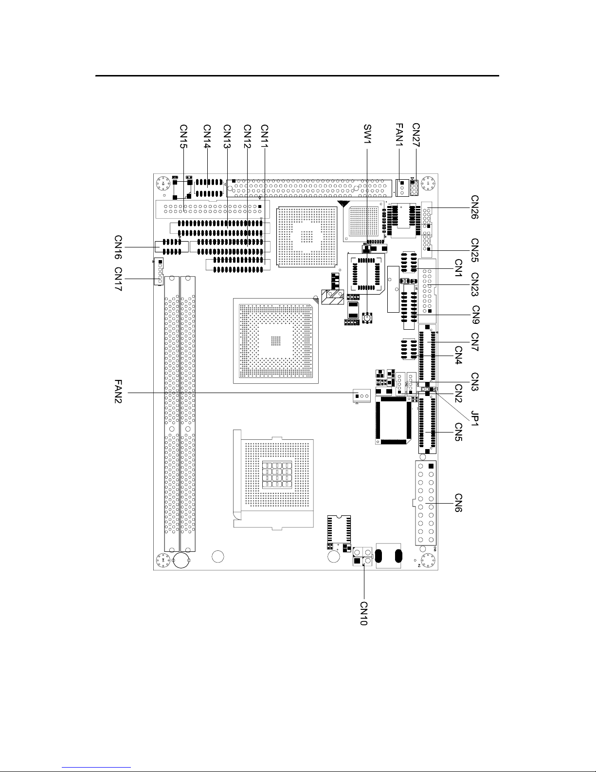
2.2 Connectors
On-board connectors link the PCM-9580 to external devices such as hard
disk drives, a keyboard, or floppy drives. The table below lists the func-
tion of each of the board’s connectors.
Table 2.2: Connectors
Label Function
CN1 USB channel 3, 4 connector
CN2 TV-out connector (optional)
CN3 Backlight control connector
CN4 AC97 (Audio) connector
CN5 LVDS connector
CN6 ATX 12 V power connector
CN7 4COM port connector
CN9 CRT display connector
CN10 ATX 12 V power connector
CN11 Parallel port connector
CN12 Floppy drive connector
CN13 IDE hard drive connector (secondary)
CN14 Clear CMOS
CN15 IDE hard drive connector (primary)
CN16 4 bit GPIO connector
CN17 Keyboard and PS/2 mouse connector
CN19 CFC connector
CN23 Embedded USB
CN25 10/100Base-T Ethernet connector (PCM-9580F)
CN26 Gigabit Ethernet connector(PCM-9580FG)
CN27 Gigabit LAN LED connector
Fan2 CPU fan connector
SW1 reset button connector
Fan1 System fan power connector
PCM-9580 User’s Manual 10
2.3 Locating jumpers and Connectors
Figure 2.1: Jumper & Connector (component side)

11 Chapter2
2.4 Setting Jumpers
You may configure your card to match the needs of your application by
setting jumpers. A jumper is a metal bridge used to close an electric cir-
cuit. It consists of two metal pins and a small metal clip (often protected
by a plastic cover) that slides over the pins to connect them. To “close” a
jumper, you connect the pins with the clip. To “open” a jumper, you
remove the clip. Sometimes a jumper will have three pins, labeled 1, 2
and 3. In this case you would connect either pins 1 and 2, or 2 and 3.
The jumper settings are schematically depicted in this manual as follows:.
A pair of needle-nose pliers may be helpful when working with jumpers.
If you have any doubts about the best hardware configuration for your
application, contact your local distributor or sales representative before
you make any changes.
Generally, you simply need a standard cable to make most connections.
open closed closed 2-3
open closed closed 2-3

PCM-9580 User’s Manual 12
2.5 Clear CMOS (SW1)
This jumper is used to erase CMOS data and reset system BIOS informa-
tion.
The procedure for clearing CMOS is:
1. Turn off the system.
2. Push SW1
3. Turn on the system. The BIOS is now reset to its default setting
2.6 Installing DIMMs
The procedure for installing DIMMs is described below. Please follow
these steps carefully. The number of pins are different on either side of
the breaks, so the module can only fit in one way. DIMM modules have
different pin contacts on each side, and therefore have a higher pin den-
sity.
1. Make sure that the two handles of the DIMM socket are in the
“open” position. i.e. The handles remain leaning outward.
2. Slowly slide the DIMM module along the plastic guides on both
ends of the socket.
3. Press the DIMM module right down into the socket, until you hear
a click. This is when the two handles have automatically locked the
memory module into the correct position of the socket.
To remove the memory module, just push both handles outward, and the
module will be ejected from the socket.
Warning! To avoid damaging the computer, always turn off
the power supply before setting “Clear CMOS.”
Before turning on the power supply, set the
jumper back to “3.0 V Battery On.”
This manual suits for next models
1
Table of contents
Other EMAC Motherboard manuals

EMAC
EMAC PCM-4896L User manual

EMAC
EMAC PCM-6892E User manual

EMAC
EMAC MicroPac 535 Quick user guide

EMAC
EMAC PCA-6782 User manual

EMAC
EMAC SBC-675 User manual

EMAC
EMAC PCM-5315 User manual

EMAC
EMAC SBC-557 User manual

EMAC
EMAC PCM-4896 User manual

EMAC
EMAC iPac HCS12 User manual

EMAC
EMAC PCM-5864 User manual


