EMAC PCA-6782 User manual

User Manual
PCA-6782
Intel
®
Atom™ Dual-Core D525/
Fanless N455 CPU, ISA Half-size
SBC with VGA / LVDS / Single-GbE /
SATA / COM

PCA-6782 User Manual ii
Copyright
The documentation and the software included with this product are copyrighted 2010
by WKHPDQXIDFWXUHU. All rights are reserved. 7KHPDQXIDFWXUHU reserves the right
to make improvements in the products described in this manual at any time without
notice.
No part of this manual may be reproduced, copied, translated or transmitted in any
form or by any means without the prior written permission of WKHPDQXIDFWXUHU.
Information provided in this manual is intended to be accurate and reliable. However,
WKHPDQXIDFWXUHU assumes no responsibility for its use, nor for any infringements
of the rights of third parties, which may result from its use.
Certifications
CE
FCC Class A
Part No. 2002678200 Edition 1
December 2010

PCA-6782 User Manual iv
Product Warranty (2 years)
7KHPDQXIDFWXUHU warrants to you, the original purchaser, that each of its products will be
free from defects in materials and workmanship for two years from the date of pur-
chase.
This warranty does not apply to any products which have been repaired or altered by
persons other than repair personnel authorized by WKHPDQXIDFWXUHU, or which have been
subject to misuse, abuse, accident or improper installation. 7KHPDQXIDFWXUHU assumes no
liability under the terms of this warranty as a consequence of such events.
Because of WKHPDQXIDFWXUHU’s high quality-control standards and rigorous testing, most of
our customers never need to use our repair service. If a product is defecWLYH
it will be repaired or replaced at no charge during the warranty period. For out-
of-warranty repairs, you will be billed according to the cost of replacement materials,
service time and freight. Please consult your dealer for more details.
If you think you have a defective product, follow these steps:
1. Collect all the information about the problem encountered. (For example, CPU
speed, other hardware and software used, etc.) Note DQ\WKLQJDEQRUPDODQG
list any onscreen messages you get when the problem RFFXUV
2. Call your dealer and describe the problem. Please have your manual, product,
and any helpful information readily available.
3. If your product is diagnosed as defective, obtain an RMA (return merchandise
authorization) number from your dealer. This allows us to process your return
more quickly.
4. Carefully pack the defective product, a fully-completed Repair and Replacement
Order Card and a photocopy proof of purchase date (such as your sales receipt)
in a shippable container. A product returned without proof of the purchase date
is not eligible for warranty service.
5. Write the RMA number visibly on the outside of the package and ship it prepaid
to your dealer.
Before you begin installing your single board computer, please make sure that the
following materials have been shipped:
If any of these items are missing or damaged, contact your distributor or sales repre-
sentative immediately.
We have carefully inspected the PCA-6782 mechanically and electrically before ship-
ment. It should be free of marks and scratches and in perfect working order upon
receipt.
As you unpack the PCA-6782, check it for signs of shipping damage. (For example,
damaged box, scratches, dents, etc.) If it is damaged or it fails to meet the specifica-
tions, notify our service department or your local sales representative immediately.
Also notify the carrier. Retain the shipping carton and packing material for inspection
by the carrier. After inspection, we will make arrangements to repair or replace the
unit.

v PCA-6782 User Manual
Initial Inspection
Before you begin installing your single board computer, please make sure that the
following materials have been shipped:
If any of these items are missing or damaged, contact your distributor or sales repre-
sentative immediately.
We have carefully inspected the PCA-6782 mechanically and electrically before ship-
ment. It should be free of marks and scratches and in perfect working order upon
receipt.
As you unpack the PCA-6782, check it for signs of shipping damage. (For example,
damaged box, scratches, dents, etc.) If it is damaged or it fails to meet the specifica-
tions, notify our service department or your local sales representative immediately.
Also notify the carrier. Retain the shipping carton and packing material for inspection
by the carrier. After inspection, we will make arrangements to repair or replace the
unit.
!1 PCA-6782D(N) single board computer
!1 CPU Cooler for Atom D525 CPU (Only Available for D SKU) P/N: 1960046526N001
!1 PCA-6782 Startup Manual
!1 CD with driver utility and manual (in PDF format)
!1 Ultra ATA 66/100 HDD cables P/N: 1701400452
!2 Serial ATA HDD data cable P/N: 1700003194
!2 Serial ATA HDD power cable P/N: 1703150102
!1 Print port & COM part cable kit P/N: 1700008954
!1 ATX Feature Cable P/N: 1700002343
!1 4-Port USB cable kit P/N: 1700014398
!1 Y cable for PS/2 keyboard and PS/2 mouse P/N: 1700060202
!1 ATX power cable 20P/7P 10cm P/N: 1703070101
!1 AT Power Cable P/N: 1703080101
!1 Jumper Pack P/N: 9689000002
!1 Warranty card
Note! Using PCA-6782D's proprietary CPU cooler included in its package is a
must. Other brands of CPU coolers are NOT compatible with PCA-6782.
PCA-6782N is a fanless CPU type and does not require installing a CPU
cooler.

PCA-6782 User Manual vi
Verified Memory List
Brand Size Speed Type ECC Vendor PN
PN Memory
Tran-
scend
256
MB
DDR2
667
SODIMM
DDR2 N TS32MSQ64V6M NA Hynix HY5PS121621B FP-Y5
(32x16)
512
MB
DDR2
667
SODIMM
DDR2 NTS6QSJ23002-6S/
TS64MSQ64V6J
96SD2-
512M667NN-
TR
SAMSUNG K4T51083QC ZCE6
(64x8)
512
MB
DDR2
667
SODIMM
DDR2 N
Hynix
HY5PS121621B
FP-Y5
NA Hynix HY5PS121621B FP-Y5
(32x16)
1 GB DDR2
667
SODIMM
DDR2 N TS128MSQ64V6J NA SAMSUNG K4T51083QC ZCE6
(64x8)
2 GB DDR2
667
SODIMM
DDR2 N TS5QSU27300-6M 96SD2-
2G667NN-TR Micron D9HNL (128x8)
Apacer
512
MB
DDR2
667
SODIMM
DDR2 N 78.92G63.422 NA ELPIDA E5108AG-6E-E (64x8)
1 GB DDR2
667
SODIMM
DDR2 N 78.02G63.423 96SD2-
1G667NN-AP
ELPIDA E5108AGBG-6E-E
(64x8)
2 GB DDR2
667
SODIMM
DDR2 N 78.A2G72.425
96SD2-
2G667NN-
AP1
ELPIDA E1108AFBG-8E-F
(128x8)
DSL
256
MB
DDR2
667
SODIMM
DDR2 N NA NA ELPIDA E5116AF-6E-E (32x16)
512
MB
DDR2
667
SODIMM
DDR2 NNA NA ELPIDA E5108AGBG-6E-E
(64x8)
1 GB DDR2
667
SODIMM
DDR2 NNA NA ELPIDA E5108AGBG-6E-E
(64x8)
2 GB DDR2
667
SODIMM
DDR2 NNA NA ELPIDA E1108ACSE-6E-E
(128x8)
vii PCA-6782 User Manual
Certification and Safety Instructions
This device complies with the requirements in part 15 of the FCC rules: Operation is
subject to the following two conditions:
1. This device may not cause harmful interference, and
2. This device must accept any interference received, including interference that
may cause undesired operation
This equipment has been tested and found to comply with the limits for a Class A dig-
ital device, pursuant to Part 15 of the FCC Rules. These limits are designed to pro-
vide reasonable protection against harmful interference when the equipment is
operated in a commercial environment. This equipment generates, uses, and can
radiate radio frequency energy and, if not installed and used in accordance with the
instruction manual, may cause harmful interference to radio communications. Opera-
tion of this device in a residential area is likely to cause harmful interference in which
case the user will be required to correct the interference at his/her own expense. The
user is advised that any equipment changes or modifications not expressly approved
by the party responsible for compliance would void the compliance to FCC regula-
tions and therefore, the user's authority to operate the equipment.
Caution! There is a danger of a new battery exploding if it is incorrectly installed.
Do not attempt to recharge, force open, or heat the battery. Replace the
battery only with the same or equivalent type recommended by the man-
ufacturer. Discard used batteries according to the manufacturer's
instructions.

PCA-6782 User Manual viii

ix PCA-6782 User Manual
Contents
Chapter 1 Hardware Configuration......................1
1.1 Introduction ............................................................................................... 2
1.2 Features .................................................................................................... 2
1.3 Specifications ............................................................................................ 3
1.3.1 System .......................................................................................... 3
1.3.2 Memory ......................................................................................... 3
1.3.3 Input/Output .................................................................................. 3
1.3.4 Graphic interface........................................................................... 3
1.3.5 Ethernet LAN ................................................................................ 4
1.3.6 Industrial features ......................................................................... 4
1.3.7 Mechanical and environmental specifications............................... 4
1.4 Jumpers and Connectors .......................................................................... 5
Table 1.1: Jumper descriptions ................................................... 5
Table 1.2: Connector descriptions............................................... 5
1.5 Board Layout: Jumper and Connector Locations...................................... 7
Figure 1.1 Board Layout .............................................................. 7
1.6 PCA-6782 Block Diagram ......................................................................... 8
Figure 1.2 Block Diagram ............................................................ 8
1.7 Safety Precautions .................................................................................... 8
1.8 System Memory ........................................................................................ 9
1.9 Memory Installation Procedures................................................................ 9
1.10 Processor Installation.............................................................................. 10
1.11 CPU Cooler Installation........................................................................... 10
Chapter 2 Connecting Peripherals & Jumper
Settings ..............................................11
2.1 Introduction ............................................................................................. 12
2.2 IDE Connector (IDE1) ............................................................................. 12
Figure 2.1 PCA-6782 IDE1 location........................................... 12
2.3 Floppy Drive Connector (FDD1).............................................................. 13
Figure 2.2 PCA-6782 FDD1 location ......................................... 13
2.4 Parallel Port (LPT1)................................................................................. 14
Figure 2.3 PCA-6782 LPT1 location .......................................... 14
2.5 VGA Connector (VGA1) .......................................................................... 15
Figure 2.4 VGA Connector (VGA1) ........................................... 15
2.6 Serial Ports (COM1, COM2) ................................................................... 15
Figure 2.5 Serial Ports (COM1, COM2)..................................... 15
2.7 PS/2 Keyboard/Mouse Connector (KBMS1) ........................................... 16
Figure 2.6 PS/2 Keyboard/Mouse Connector (KBMS1) ........... 16
2.8 External Keyboard Pin Header (KBMS2) ................................................ 17
Figure 2.7 External Keyboard Connector (KBMS2).................. 17
2.9 CPU Fan Connectors (CPUFAN1).......................................................... 17
Figure 2.8 CPU Fan Connectors (CPUFAN1) .......................... 17
2.10 Front Panel Connectors (JFP1) ............................................................. 18
Figure 2.9 Front Panel Connectors (JFP1)............................... 18
2.10.1 ATX Power Button (JFP1 Pin 9~10) ........................................... 18
2.10.2 Reset (JFP1 Pin 7~8) ................................................................. 18
2.10.3 Suspend LED (JFP1 Pin 5~6)..................................................... 18
2.10.4 Power LED and keyboard lock connector (JFP1 Pin 3~4).......... 18
Table 2.1: ATX power supply LED status (No support for AT pow-
er) ............................................................................. 18
2.10.5 HDD LED (JFP1 Pin 1~2) ........................................................... 19

PCA-6782 User Manual x
2.11 Watch Dog Timer (JWDT1) / Infrared (JIR1) .......................................... 19
Figure 2.10Watch Dog Timer (JWDT1) / Infrared (JIR1)............ 19
2.11.1 Watchdog timer output (JWDT1) ................................................ 19
Table 2.2: Watchdog timer output (JWDT1).............................. 19
2.11.2 Infrared Connector (JIR1) ........................................................... 19
2.12 Single Giga LAN RJ45 connector (LAN1)............................................... 20
Figure 2.11Single Giga LAN RJ45 connector (LAN1) ................ 20
2.13 Serial ATA interface (SATA1 ~ SATA3).................................................. 20
Figure 2.12Serial ATA interface (SATA1 ~ SATA3) ................... 20
2.14 GPIO header (GPIO1) ............................................................................ 21
Figure 2.13 GPIO header (GPIO1)............................................. 21
2.15 LVDS panel power selection (JLVDS1) .................................................. 21
Table 2.3: LVDS panel power selection (JLVDS1).................... 21
2.16 LVDS VBR selection (JVBR1) ................................................................ 22
Table 2.4: LVDS VBR selection (JVBR1).................................. 22
2.17 CMOS clear (CMOS1) ............................................................................ 22
Table 2.5: CMOS (CMOS1) ...................................................... 22
2.18 ATX Feature connector(ATXF1) ............................................................. 23
2.19 ATX power control connector (ATX1) ..................................................... 24
2.20 System FAN connector (SYSFAN1) ....................................................... 24
2.21 LVDS Signal and Power Connectors (LVDS1) ....................................... 25
2.22 USB Ports (USB 1 ~ 8) ........................................................................... 25
2.23 CF Card Socket ...................................................................................... 26
2.24 Low Pin Count Device Connection Pin Header ...................................... 26
Chapter 3 AMI BIOS Setup................................. 27
Figure 3.1 Setup Program Initial Screen ................................... 28
3.1 Entering Setup ........................................................................................ 29
3.2 Main Setup.............................................................................................. 29
Figure 3.2 Main Setup Screen................................................... 29
3.2.1 System time / System date ......................................................... 29
3.3 Advanced BIOS Features Setup............................................................. 30
Figure 3.3 Advanced BIOS Features Setup Screen.................. 30
3.3.1 CPU Configuration...................................................................... 31
Figure 3.4 CPU Configuration Settings ..................................... 31
3.3.2 IDE Configuration ....................................................................... 32
Figure 3.5 IDE Configuration ..................................................... 32
3.3.3 Super I/O Configuration .............................................................. 33
Figure 3.6 Super I/O Configuration............................................ 33
3.3.4 Hardware Health Function .......................................................... 34
Figure 3.7 Hardware Health Configuration. ............................... 34
3.3.5 APM Configuration...................................................................... 35
Figure 3.8 APM Configuration ................................................... 35
3.4 Event Logging Details ............................................................................. 36
Figure 3.9 Event Logging Details .............................................. 36
3.5 USB Configuration .................................................................................. 36
Figure 3.10USB Configuration.................................................... 36
3.6 PCI/PNP Setup ....................................................................................... 37
Figure 3.11PCI/PNP Setup......................................................... 37
3.7 Boot Setup Utility .................................................................................... 38
Figure 3.12Boot Settings Configuration...................................... 38
3.8 Security Setup......................................................................................... 39
Figure 3.13Password Configuration ........................................... 39
3.9 Advanced Chipset Settings..................................................................... 40
Figure 3.14Advanced Chipset Settings ...................................... 40
Figure 3.15South Bridge Configuration ...................................... 42
3.10 Exit Options............................................................................................. 43
Figure 3.16Exit Options .............................................................. 43

xi PCA-6782 User Manual
3.10.1 Save Changes and Exit .............................................................. 43
3.10.2 Discard Changes and Exit .......................................................... 43
3.10.3 Discard Changes ........................................................................ 43
3.10.4 Load Optimal Defaults ................................................................ 44
3.10.5 Load Failsafe Defaults ................................................................ 44
Chapter 4 Value-Added Software Services.......45
4.1 Value-Added Software Services ............................................................. 46
4.1.1 Software API ............................................................................... 46
4.1.2 Software Utility ............................................................................ 48
Chapter 5 Chipset Software Installation Utility 49
5.1 Before You Begin .................................................................................... 50
5.2 Introduction ............................................................................................. 50
5.3 Windows 7/XP Driver Setup.................................................................... 51
Chapter 6 Integrated Graphic Device Setup .....53
6.1 Introduction ............................................................................................. 54
6.2 Windows 7/XP Driver Setup.................................................................... 54
Chapter 7 LAN Configuration.............................55
7.1 Introduction ............................................................................................. 56
7.2 Installation ............................................................................................... 56
7.3 Windows 7/XP Driver Setup.................................................................... 56
Appendix A Programming the Watchdog Timer..57
A.1 Watchdog Timer...................................................................................... 58
A.1.1 Watchdog Timer Overview.......................................................... 58
A.1.2 Reset/ Interrupt Selection ........................................................... 58
A.1.3 Programming the Watchdog Timer ............................................. 59
Table A.1: Watchdog Timer Registers ....................................... 60
A.1.4 Example Program ....................................................................... 61
Appendix B I/O Pin Assignments..........................65
B.1 Front Panel Connectors (JFP1) .............................................................. 66
Table B.1: Front Panel Connectors (JFP1)................................ 66
B.2 USB Ports (USB12/USB34/USB56/USB78) ........................................... 66
Table B.2: USB Ports (USB12/USB34/USB56/USB78)............. 66
B.3 IR Connector (JIR1) ................................................................................ 67
Table B.3: IR Connector (JIR1).................................................. 67
B.4 Serial port (COM1) .................................................................................. 67
Table B.4: Serial port (COM1)................................................... 67
B.5 Serial port (COM2) .................................................................................. 68
Table B.5: Serial port (COM2) ................................................... 68
B.6 PS/2 keyboard and mouse connector (KBMS1) ..................................... 68
Table B.6: PS/2 keyboard and mouse connector (KBMS1)....... 68
B.7 External keyboard and mouse connector (KBMS2) ................................ 69
Table B.7: External keyboard and mouse connector (KBMS2) . 69
B.8 ATX Feature connector(ATXF1) ............................................................. 69

PCA-6782 User Manual xii
Table B.8: ATX Feature connector(ATXF1)............................... 69
B.9 CPU FAN connector (CPUFAN1) ........................................................... 70
Table B.9: CPU FAN connector (CPUFAN1)............................. 70
B.10 System FAN connector (SYSFAN1) ....................................................... 70
Table B.10:System FAN connector (SYSFAN1)......................... 70
B.11 Audio Interface Connector (HDAUD1) .................................................... 70
Table B.11:Audio Interface Connector (HDAUD1) ..................... 70
B.12 GPIO Header (GPIO1)............................................................................ 71
Table B.12:GPIO Header (GPIO1) ............................................. 71
B.13 LVDS Connector (LVDS1) ...................................................................... 71
Table B.13:LVDS Connector (LVDS1)........................................ 71
B.14 LCD Inverter Connector (INV1)............................................................... 72
Table B.14:LCD Inverter Connector (INV1) ................................ 72
B.15 Low Pin Count Header (LPC1) ............................................................... 72
Table B.15:Low Pin Count Header (LPC1)................................. 72
B.16 ATX Power Control Connector (ATX1) ................................................... 73
Table B.16:ATX Power Control Connector (ATX1)..................... 73
B.17 VGA Connector (VGA1).......................................................................... 73
Table B.17:VGA Connector (VGA1) ........................................... 73
B.18 Negative power input connector (12V1).................................................. 74
Table B.18:Negative power input connector (12V1) ................... 74
B.19 Case open (JCASE1).............................................................................. 74
Table B.19:Case open (JCASE1) ............................................... 74
B.20 FDD connector (FDD1) ........................................................................... 75
Table B.20:FDD connector (FDD1) ............................................ 75
B.21 Parallel port connector (LPT1) ................................................................ 76
Table B.21:Parallel port connector (LPT1) ................................. 76
B.22 IDE connector (IDE1).............................................................................. 77
Table B.22:IDE connector (IDE1) ............................................... 77
B.23 Serial ATA (SATA1/SATA2/SATA3) ....................................................... 78
Table B.23:Serial ATA (SATA1/SATA2/SATA3)......................... 78
B.24 HW Monitor Alarm (JOBS1).................................................................... 78
Table B.24:Serial ATA (SATA1/SATA2/SATA3)......................... 78
B.25 LVDS VBR selection (JVBR1) ................................................................ 79
Table B.25:LVDS VBR selection (JVBR1).................................. 79
B.26 LVDS panel power selection (JLVDS1) .................................................. 79
Table B.26:LVDS panel power selection (JLVDS1).................... 79
B.27 Watchdog timer output selection (JWDT1) ............................................. 79
Table B.27:Watchdog timer output selection (JWDT1)............... 79
B.28 CMOS clear (CMOS1) ............................................................................ 80
Table B.28:CMOS clear (CMOS1).............................................. 80
B.29 System I/O Ports..................................................................................... 80
Table B.29:System I/O ports....................................................... 80
B.30 DMA Channel Assignments .................................................................... 81
Table B.30:DMA channel assignments....................................... 81
B.31 Interrupt Assignments ............................................................................. 81
Table B.31:Interrupt assignments............................................... 81
B.32 1st MB Memory Map............................................................................... 82
Table B.32:1st MB memory map ................................................ 82
Appendix C Programming the GPIO .................... 83
C.1 Supported GPIO Register ....................................................................... 84
C.1.1 GPIO Registers........................................................................... 84
C.1.2 GPIO Example Program-1.......................................................... 85

Chapter 1
1Hardware
Configuration

PCA-6782 User Manual 2
1.1 Introduction
PCA-6782 is an Intel®Atom™ dual-core D525 / fanless N455 CPU based ISA-inter-
face half-size single board computer. With high performance Atom D525 dual-core
computing power, it is ideal for intense data or graphic processing applications; with
fanless Atom™ N455 CPU, it has ultra high reliability to resist heat, dust, vibration
and shock in any application environment.
PCA-6782 is designed with an Intel®Atom™ D525/N455 CPU and ICH8M I/O control
hub. The Atom™ D525 dual core CPU brings new generation computing capability
into the half-size SBC application field. Compact size, low power consumption (Total
power consumption ≤17.62 W) and dual-core parallel computing power and maxi-
mum 2 GB of DDR2 667 MHz memory capacity makes the PCA-6782D a powerful
small form-factor computer platform for modern industrial applications that require
high computing power. The fanless Atom™ N455 CPU (Total power consumption ≤
12.56 W) is ideal for data-acquisition, environment monitoring system and factory
automation that requires no air flow environments.
PCA-6782 has an integrated graphic core of Intel Embedded Gen3.5+ graphic tech-
nology with 224 MB shared memory. This feature makes PCA-6782 is capable of
handling complex and intense 2D/3D graphic processing without an add-on graphic
card; its VGA and LVDS dual video outputs also makes it suitable for applications
requiring dual display or digital panel display capabilities.
PCA-6782 is rich in I/O interfaces: it has three SATA ports (300 MB/sec) for main-
stream SSD (solid state disk), HDD, and ODD connections, one legacy IDE port for
the ODD connection. It also has a CF socket to support an economical, easy-to-
maintain SSD device. Additionally, the two serial ports (COM ports) can be used as
reliable legacy device control interfaces. Users can also purchase WKH COMSRUW
upgrade module (P/N: PCA-COM485-00A1E) to have four extra RS485 ports
with auto flow control capability.
1.2 Features
!Ultra low power (Total Power Consumption ≤12.56 W), fanless N455 CPU and
maximum 2 GB DDR2 667 memory (Only for N SKU)
!Dual-core D525 CPU and maximum 2 GB DDR2 667 memory (Only for D SKU)
!Intel® Embedded Gen3.5+ graphics core with 224 MB of shared memory with
VGA/LVDS dual video outputs (supporting clone and extension modes)
!Supports single-Gigabit Ethernet LANs with teaming capability
!Supports Embedded Software SUSI APIs and Utilities. (SUSI APIs: watchdog,
hardware monitor, brightness control, programmable GPIO, backlight On/Off;
Utilities: BIOS flash, eSOS (Requires BIOS Customization), system monitoring,
Flash Lock, software protection)

3 PCA-6782 User Manual
Chapter 1 Hardware Configuration
1.3 Specifications
1.3.1 System
!CPU: Soldered-down (BGA type) Intel®Atom™ 1.8 GHz D525 dual-core CPU
or 1.66GHz N455 fanless CPU
!L2 Cache: CPU built-in 1 MB / 512 KB L2 cache
!BIOS: AMI BIOS
!System Chipset: Intel®ICH8M
!SATA/EIDE hard disk drive interface: Supports up to 3 independent Serial
ATA hard drives (up to 300 MB/s) as well as one IDE port (maximum 2 devices)
!Floppy disk drive interface: Supports up to two floppy disk drives, 51/4(360
KB and 1.2 MB) and/or 31/2(720 KB, 1.44 MB). BIOS enabled/disabled.
1.3.2 Memory
!RAM:
–N and D SKU: Maximum 2 GB DDR2 667 MHz memory in SO-DIMM socket
1.3.3 Input/Output
!Enhanced parallel port: Configurable to LPT1 or disabled. Standard DB-25
female connector provided. Supports EPP/ECP
!Serial ports: Two dedicated serial RS-232 ports on board, plus four ports RS-
422/485 w/ autoflow control by module (Optional, P/N: PCA-&20$(
!Keyboard and PS/2 mouse connector: One 6-pin mini-DIN connector is
located on the mounting bracket for easy connection to a keyboard or PS/2
mouse. An on board keyboard pin header connector is also available
!High Definition Audio: PCA-6782 can provide audio function with the optional
audio extension module PCA-AUDIO-HDA1E
!USB ports: PCA-6782 supports up to 8 USB 2.0 ports with transmission rates
up to 480 Mbps
1.3.4 Graphic interface
!Controller: Integrated graphics core of Embedded Gen3.5+ technology
!VRAM: 224 MB shared system memory
!Output Interfaces:
–VGA: Supports up to SXGA 1400 x 1050 @ 60Hz for Atom N455, up to 2048
x 1536 @ 60 Hz for Atom D525
–LVDS: Supports 18-bit single channel and up to WXGA 1366 x 768 or 1280 x
800 for both Atom D525 and N455 CPUs
–Dual Display: VGA + LVDS, supports extended mode and clone mode
Note! PCA-6782 is ONLY compatible with DDR2 memory modules that are
assembled with x16 (16-bit) memory chips and NOT compatible with
those that are assembled with x8 (8-bit) memory chips. Using wrong
memory modules may cause unexpected system instability.

PCA-6782 User Manual 4
1.3.5 Ethernet LAN
!Supports single 10/100/1000 Mbps Ethernet networking
!Controller: Intel®82567V
1.3.6 Industrial features
!Watchdog timer: Can generate a system reset. The watchdog timer is pro-
grammable, with each unit equal to one second or one minute (255 levels). You
can find programming details in Appendix A
!Fanless N455 CPU for N SKU for ultra high reliability and long MTBF
1.3.7 Mechanical and environmental specifications
!Operating temperature: 0 ~ 60° C (32 ~ 140° F)
!Storage temperature: -40 ~ 85° C (-40 ~ 185° F)
!Humidity: 20 ~ 95% non-condensing
!Demanded Power supply voltage: +12 V, +5 V, +5 VSB
!Power consumption:
–D SKU:
CPU: Dual-core Atom D525 CPU 1.8 GHz
Memory: 1 Piece of 2 GB DDR2 667 MHz SO-DIMM
Storage: One SATA HDD
Test program: Hot CPU pro 4.22
+12 V: 0.46 A
+5 V: 2.41 A
+3.3 V: 0 A
+5 VSB: 0.01 A
-12 V: 0 A
-5 V: 0 A
Total Power Consumption: 17.62 W
–N SKU:
CPU: Single Core Atom N455 CPU 1.66 GHz
Memory: 1 Piece of 2 GB DDR2 667 MHz SO-DIMM
Storage: One STA HDD
Test Program: Hot CPU pro 4.22
+12 V: 0.13 A
+5 V: 2.19 A
+3.3 V: 0 A
+5 VSB: 0.01 A
-12 V: 0 A
-5 V: 0 A
Total Power Consumption: 12.56 W
!Board size: 185 mm (L) x 122 mm (W) (7.3" x 4.8")
!Board weight: 0.225 Kg (weight of board)

5 PCA-6782 User Manual
Chapter 1 Hardware Configuration
1.4 Jumpers and Connectors
Connectors on the PCA-6782 single board computer link it to external devices such
as hard disk drives and a keyboard. In addition, the board has a number of jumpers
used to configure your system for your application.
Below, Tables 1.1 and 1.2 list the jumper and connector functions. Later sections in
this chapter give instructions on setting jumpers. Chapter 2 gives instructions for con-
necting external devices to your single board computer.
Table 1.1: Jumper descriptions
Label Function
CMOS1 CMOS Clear
JWDT1 Watchdog timer output option
JLVDS1 LVDS panel pow e r s e le c ti o n
JVBR1 LV D S V B R s election
Table 1.2: Connector descriptions
Label Function
IDE1 Primary IDE connector
FDD1 Floppy drive connector
LPT1 Parallel port
VGA1 VGA connector
LVDS1 LVDS Pin-header
COM1 Serial port: COM1; RS232 (9-pin D-sub)
COM2 Serial port: COM2; RS-232 (14-pin 2.00 pitch box header)
KBMS1 PS/2 keyboard and mouse connector
KBMS2 External keyboard/mouse pin header
JIR1 Infrared port pin header
CPUFAN1 3-pin Atom D525 CPU fan connector
SYSFAN1 3-pin System fan connector
JFP1 Power and Reset Button connector
LAN1 Single Giga LAN RJ45 connector with Transformer
HDAUD1 High Definition Audio interface connector
SATA1 Serial ATA1
SATA2 Serial ATA2
SATA3 Serial ATA3
USB 12 USB port 1 and port 2 pin-header
USB 34 USB port 3 and port 4 pin-header
USB 56 USB port 5 and port 6 pin-header
USB 78 USB port 7 and port 8 pin-header
GPIO1 GPIO header
JOBS1
HW Monitor Alarm
Close: Enable OBS Alarm
Open: Disable OBS Alarm
PC1 PC104 connector
JCASE1 Case open
DIMMB1 Memory connector channel B

PCA-6782 User Manual 6
INV1 LCD inverter connector
CF1 CF Socket
ATXF1 ATX feature connector
ATX1 ATX power connector
12V1 Negative power input connector
LPC1 Low pin count connector
Table 1.2: Connector descriptions

7 PCA-6782 User Manual
Chapter 1 Hardware Configuration
1.5 Board Layout: Jumper and Connector
Locations
Figure 1.1 Board Layout
PCA-6782 User Manual 8
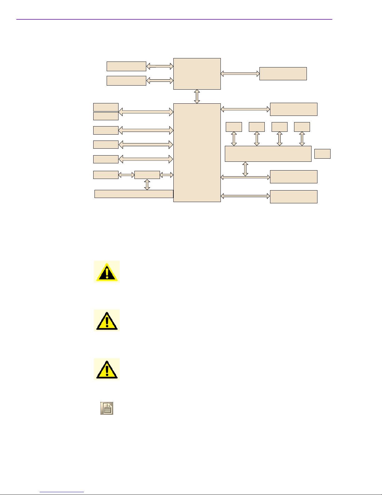
1.6 PCA-6782 Block Diagram
Figure 1.2 Block Diagram
1.7 Safety Precautions
Atom D525
Atom N455
CPU
CRT
LVDS 18bit
IDE
CFC
3 SATA
8 USB
BIOS
PC104 ITE8888G
ISA Golden Finger
ICH8M
SODIMM DDR2 667
Socket to 2 G Max
G-LAN1: Intel 82567V
2 COM
8-bit GPIO
Super IO
W83627DHG-P
4 COM With Auto
flow Control (Optional)
ALC 888 Codec
PCA-AUDIO-HDA1E (Optional)
FDD PS2 LPT
Single channel
x4 DMI
VGA
LVDS
IDE
300 MB/s
USB 2.0
SPI
ISA
LCI & GLCI
Single LAN
LPC Bus
HD Audio
ISA
Warning! Always completely disconnect the power cord from your chassis when-
ever you work with the hardware. Do not make connections while the
power is on. Sensitive electronic components can be damaged by sud-
den power surges. Only experienced electronics personnel should open
the PC chassis.
Caution! Always ground yourself to remove any static charge before touching the
single board computer. Modern electronic devices are very sensitive to
electrostatic discharges. As a safety precaution, use a grounding wrist
strap at all times. Place all electronic components on a static-dissipative
surface or in a static-shielded bag when they are not in the chassis.
Caution! The computer is provided with a battery-powered real-time clock circuit.
There is a danger of explosion if battery is incorrectly replaced. Replace
only with same or equivalent type recommended by the manufacturer.
Discard used batteries according to manufacturer's instructions.
Note! Before installing your PCA-6782 into a chassis, make sure that no com-
ponents on either side of the CPU card can touch any metal parts, espe-
cially the chassis wall and add-on card in the adjacent slot.
9 PCA-6782 User Manual
Chapter 1 Hardware Configuration
1.8 System Memory
The PCA-6782D has one SO-DIMM socket. PCA-6782 is ONLY compatible with
DDR2 memory modules that are assembled with x16 (16-bit) memory chips and NOT
compatible with those that are assembled with x8 (8-bit) memory chips. Using wrong
memory modules may cause system instability and unexpected behavior.
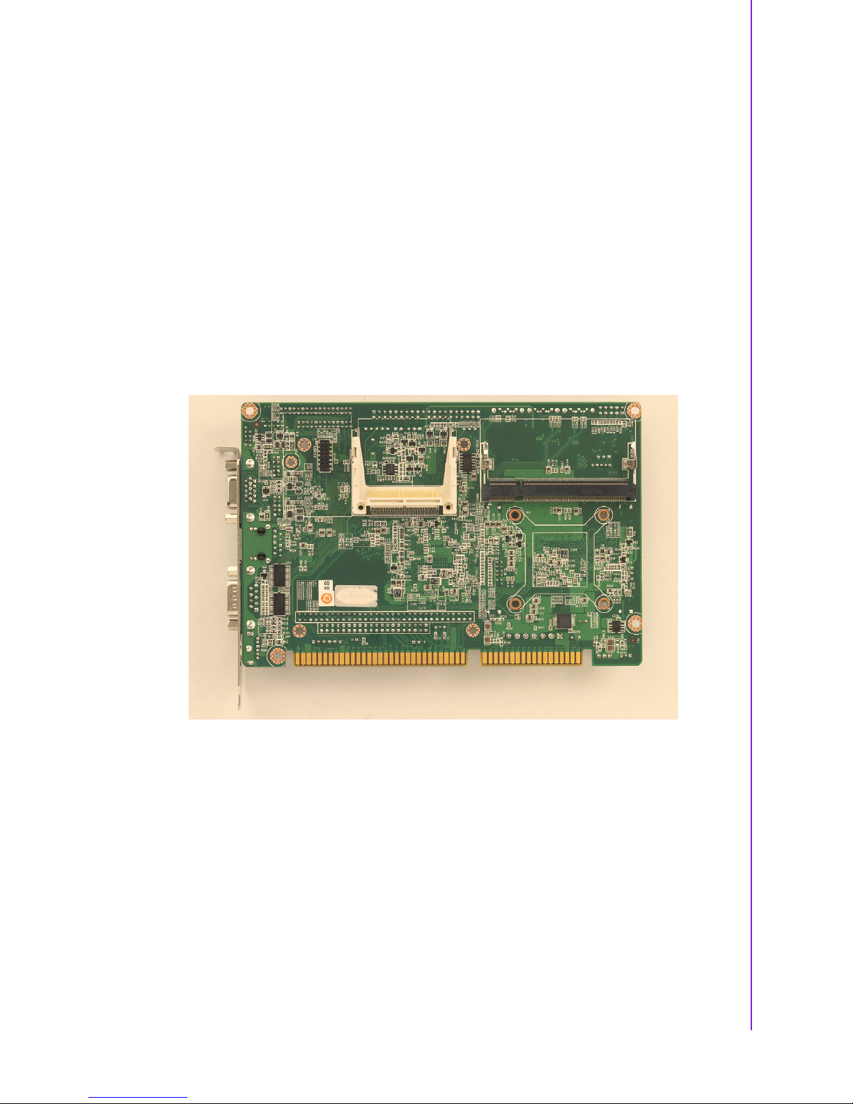
1.9 Memory Installation Procedures
1. See picture below to locate DIMMB1 200-pin SODIMM socket.
2. A memory module and expansion socket are keyed. The plastic bridge in the
socket must align with the notch in the module. The keyed bridge and notch
make sure a SODIMM cannot be installed going the wrong direction.
3. Insert the SODIMM module into the socket at a 30-45 degree angle. Make sure
the notch and the module are properly aligned.
Slowly push down the SODIMM toward the CPU card PCB until the clips at each
end of the expansion socket click into place.
Table of contents
Other EMAC Motherboard manuals

EMAC
EMAC iPac HCS12 User manual

EMAC
EMAC PCM-5315 User manual

EMAC
EMAC PCA-6003 User manual

EMAC
EMAC MicroPac 535 Quick user guide

EMAC
EMAC PCM-4896 User manual

EMAC
EMAC PCM-4896L User manual

EMAC
EMAC SBC-675 User manual

EMAC
EMAC PCM-9580F-00A1 User manual

EMAC
EMAC PCM-53E52 User manual

EMAC
EMAC SoM-iMX6U User manual


