emaux GL10 User manual

USER MANUAL
GLOW+LED STRIP
Installation and Operation Manual
EMLI22080103

GLOW+LED STRIP
Installation and Operation Manual
TABLE OF
CONTENT
PAGE
2
....
2
3
....
....
P1 CONTENT
2. SPECIFICATION
2.2 DIMENSIONS (mm)
2.3 WIRING CONNECTOR TYPE AND PART NUMBER
3. DESIGN EXAMPLE
6
.... 6. HOW TO USE GLDIYSC TO CUT THE STRIP AND END CAP ASSEMBLE
1. PRODUCT INTRODUCTION
2.1 ELECTRICAL
2.4 POWER SUPPLY AND DIMMER
4
.... 4. MOUNTING
6
.... 5. ELECTRICAL INSTALLATION
7. DIMMER AND REMOTE OPERATION
7.2.1 SPECIFICATION
7.2.2 CONTROL METHOD
7.2.3 CONNECTION PORT INSTRUCTION
7.2.4 DIRECTION FOR USE
7.2.5 PWM FREQUENCY ADJUSTMENT OPERATION:
7.2.6 MULTIPLE DIMMER SET-UP
7.1 REMOTE OPERATION
7.1.1 SPECIFICATION
7.1.2 RF REMOTE BUTTON FUNCTIONS
7.1.3 WIRELESS REMOTE CONTROL CODE VALUE SETTING METHOD
7.1.4 REMOTE CONTROL ACCESSORIES INSTALLATION INSTRUCTIONS
7.2 DIMMER OPERATION
7
....

1. PRODUCT INTRODUCTION
The underwater LED strip is designed for to latest waterproof technologies in IP68. It is an extendable and top view bendable
LED light strip tube with a 120-degree beam angle and flat rectangular emission for creating underwater profile lighting.
It can be controlled by a manual or wireless remote dimmer for lighting effect tuning. The LED strip includes a range of white
CCT from 2700K/3000K/3500K/4000K/4500K/5000K/5700K/6500K. To provide a long-life span, reinforced PVC material can
resist the harm from UV, saltwater, flame solvents, and dirt, etc. There are seven type of wiring connectors are providing
mounting flexibility for layout connections.
PRODUCT INTRODUCTION P2
2. SPECIFICATION
Operation Voltage Range: DC24V
Max Power Rating/meter: 10W
Bean angle: Top view 120 degree
2.1 ELECTRICAL
2.2 DIMENSIONS (mm)
2.3 WIRING CONNECTOR TYPE AND PART NUMBER
Model
GL10
GL10SR
GL10SL
GL10LR
GL10SD
GL10BD
GL10SB
GL10BB
CODE
LED strip max 20m length
Power connector side right
Power connector side left
Power connector side both
Power connector side direct
Power connector side both direct
Power connector side bottom
Power connector side both bottom
9042915
9042901
9042903
9042905
9042907
9042909
9042911
9042913
Description
16.5mm
16.5mm
Max. Length 20m
60m 60m
16.5mm
16.5mm
120°

P3 DESIGN EXAMPLE
GL10SR GL10LR GL10SL GL10SD GL10BD
GL10SB GL10BB
Code example: 9042915 (length 5 meter, CCT 3000K) + 9042901 = 5m LED strip, color temp 3000K with power connector side
right.
2.4 POWER SUPPLY AND DIMMER
LED Dimmer with remote
24V, 240W, 100-240V AC 50/60Hz input voltage, IP67
24V, 120W, 100-240V AC 50/60Hz input voltage, IP67
Code
E042901
106328534
106328535
Description
Not in scale
Dimmer with Remote Handset
24V DC power supply provides LED strip power source and dimmer with remote control to adjust the brightness of
the strip.
Mode
Dimmer Controller
Power Supply HLG-240H-24
Power Supply HLG-120H-24
3. DESIGN EXAMPLE
Design a regular shape 10x20m rectangle pool in 3000K color temperature.
24Vdc 5A power suppler
10m 3m 7m
10m
20m
20m

MOUNTING P4
Order details for side power connection cable
length(m)Code
GL10, 10m, color temp 3000K, GL10SR connector side right
GL10, 3m, color temp 3000K, GL10SR connector side right
GL10, 7m, color temp 3000K, GL10SR connector side right
GL10, 10m, color temp 3000K, GL10SL connector side left
GL10, 20m, color temp 3000, GL10LR, connector side both
24V 5A power supply
9042915 + 9042901
9042915 + 9042901
9042915 + 9042901
9042915 +9042903
9042915 + 9042905
105328534
Description Quantity
2
1
1
1
1
6
10
3
7
10
20
To configure the connector orientation for better installation convenience, change the connector model to GL10BD for both
side straight connector and GL10SD for single end straight connector.
GL10BD GL10SD
length(m)Code
10m, color temp 3000K, power connector both side direct
3m, color temp 3000K, power connector side direct
7m, color temp 3000K, power connector side direct
10m, color temp 3000K, power connector both side direct
24V 5A power supply
9042915 + 9042909
9042915 + 9042907
9042915 + 9042907
9042915 + 9042909
105328534
Description Quantity
3
1
1
1
6
10
3
7
20
4. MOUNTING
1.Installing the Glow+ LED stripe required at least 2 people. Make sure the bending radius is not exceeded while
installation. Maximum horizontal force not exceed 10KG
The maximum horizontal force
5-10KG

P5 MOUNTING
2. Mounting clip
There are 3 different length of plastic mounting accessories to fit into the mounting and one stainless steel for corner
mounting reinforcement.
Plastic Mounting Clips Transparent 35mm
Plastic Mounting Channel Transparent 1m
Stainless steel Mounting Clip 5cm
DIY End Connector Kit
Code
GLPMC
GLPMC1M
GLSMC
GLDIYSC
Description
Good mounting example Bad mounting example
Installation direction
GLPMC GLSMC
>10mm >10mm
Installation
direction
Installation
direction
keep 10mm in natural loose
>10mm
Pulling the wire is not allowed
Mode
106090026
106090027
106090028
106090029
GLDIYSC
Bending:
Mount the cable junction in waterproof junction box when apply to outdoor mounting.
Waterproof
Connector
-V(Red)
-V(Black)

The system operation is 24Vdc only and current rating is 5A per 10 m strips. Therefore, a 120W minimum power supply is
required to turn on the light in full brightness.
5. ELECTRICAL INSTALLATION
120W
9.5m
Rated power
LED Strip length
240W
19m
Locate the power supply nearby the LED strip and connect the terminal wiring. The recommended distance is as below table.
Watts of
light
120W
18AWG
0.82mm²
2m
17AWG
1.04mm²
2.5m
16AWG
1.38mm²
3m
14AWG
2.07mm²
4m
12AWG
3.29mm²
8m
10AWG
5.62mm²
12m
1. Connect the Red wiring of LED strip to Red wire of Power Supply.
Black-GNG
Red-24V
AC Mains
Waterproof Connector
24VDC wiring diagram
GLOW+LED STRIP
2. Wiring diagram with dimmer
6. HOW TO USE GLDIYSC TO CUT THE STRIP AND END CAP ASSEMBLE
If it is necessary to cut the LED strip to fit into the layout, use the GLCUTTER to cut the length where marked for the “Dotted
Line” or “Scissor Mark”. The cut section must have the appropriate IP rated cap flex accessory to maintain water proof IP
ratings.
Follow the steps below for end cap assemble after cutting.
Cutting Mark
Anti-skidding
clip
Aluminum
mounting piece
Rubber gasket Blank end Screw GLCUTTER
GLOW+ LED STRIP
-V(Black)
+V(Red)
AC Mains
V+ V- 24V Power Supply
Connect to LED STRIP
+
-
Dimmer wiring diagram
waterproof
connector
ELECTRICAL INSTALLATION P6

Step 1 - Place the anti-skidding clip on the very end of the tubing with the 2 tiny tabs that are pointing inwards still touching
the end of the material and crimp in place.
Step 2 - Line up the aluminum mounting piece so the screw hole face the plug and slide on over the anti-skidding clip.
Step 3 - Apply 100% clear silicone onto the end face of led neon flex
Step 4 - Place the rubber gasket squarely onto the end face of led neon flex.
Step 5 - Screw the blank end to the aluminum mounting piece.
Step 1 Step2
Step3 Step4 Step5 finished assembly view
Code
106090030
Description
LED Neon Cutter
Model
GLCUTTER
7. DIMMER AND REMOTE OPERATION
7.1 Remote Operation
7.1.1 Specification
Working temperature
-20-60℃
Working voltage
3V (AAA*2PCS)
Sleep current
<25uA
Emission current
<20mA
Sleep power consumption
<75uW
Emission power consumption
<60mW
Net weight
90g
Dimension
L150*W40*20 (mm)
RF distance
≤30m
RF frequency
2.4GHz
Accessories
bracket 1pc, 3M foam sponge glue 1pc, screw 2pcs, expansion tube 2pcs.
7.1.2 RF remote button functions
P7 DIMMER AND REMOTE OPERATION

Name of key
Description
ON
ON in any time
OFF
OFF in any time
Mode
3 static modes:
DIM: 20%, 50%, 100% CCT: warm white, cool white, pure white
Brightness +
Bright up the brightness by 1024 levels. Long-press will get fast adjusting.
Brightness -
Dim down the brightness by 1024 levels. Long-press will get fast adjusting.
S1-S4
Short-pressing in single zone state to show the set state of corresponding zone;
Short-pressing in overall-control state to show the set state of all zones.
Scene setting operation:
1. Selecting the right zone.
2. Pressing Scene key 5 times in 5 seconds, will enter scene setting state for corresponding
zone, zone indicator light will flash.
3. Setting the right light state with “ON/OFF”, “Brightness+/-“, DIM/CCT ring in 30 seconds
(will exit scene setting state automatically without saving when the time over 30 seconds
OR pressing other keys like “Z” or other Scene button).
4. Pressing Scene key 1 time to save and finish the scene setting operation.
Tips:
1. Scene setting operation for each zone is separately. “Scene control” will work for the
corresponding zone only in single-zone control state; will work for the all 4 zones in
overall-control state; so, it is flexible to setting up different scenes with zones.
The factory default state of Scene 1/2/3/4 is:
DIM: 10%/30%/70%/100% brightness for all zones.
Zone selection key
Zone selection, 2 seconds long-press get “all-control”, indicator lights will light up accordingly.
7.1.3 Wireless remote control code value setting method
(1) Code pairing operation: means that the receiver will only be controlled by the value code remote controller.
Ste
Operation
Instructions
1
Connecting the load to the receiver and power on it.
1. It is necessary to clear the code first, if the receiver
was coded before.
2. Batch operation can be performed within the
remote control range.
2
Select area
Select the area with the "Zone" key and the
corresponding indicator lights up
3
Press and hold “ON” on the remote control for 5 seconds, the
indicator of the remote control will flash quickly, means it enters
the pairing code transmission status.
Will automatically exit code transmission status after
60 seconds, or pressing any key to exit.
4
See the load light flashes 3 times and return to the initial state
Pairing coding is finished successfully
(2) Code clearing operation: means that the original code value of the receiver will be cleared and returned to the factory state.
Then it can be controlled by any compatible remote controller, and can learn to a new code.
Ste
Operation
Instructions
1
Connecting the load to the receiver and power on it.
1. The clearing operation should be finished within 1
minutes after the receiver is powered on. If exceeds
the time, can be powered on again.
2. Batch operation can be performed within the
remote control range.
2
Press and hold the remote control “Off” for 5 seconds. The
indicator of the remote control flashes quickly, means it enters
the clearing code transmission status. There is no need to select
the corresponding area when clearing code.
1. Will automatically exit code transmission status
after 60 seconds, or pressing any key to exit.
2. If the original remote controller is lost, the new
remote controller can be used for clearing
operations.
3
See the load light flashes 3 times and return to the initial state
Clearing coding is finished successfully
DIMMER AND REMOTE OPERATION P8

(3) Code learning operation between remote controls: Used to unify system code values or copy a new remote controls.
Since each remote controller has its own unique code at the time of delivery, when there are multiple remote controllers
in one system, one of them (for example, remote controller A) must be selected as the system code value, and the code
value of the rest remote controllers (for example, remote controller B) should be copied to the same one.
Step
Operation
Instructions
1
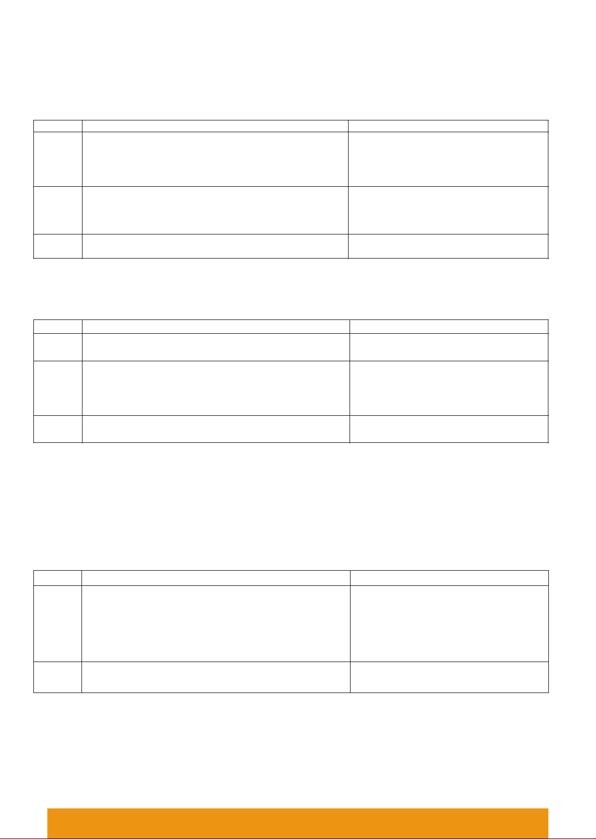
A remote control:Press and hold “ON” on the remote control
for 5 seconds, the indicator of the remote control will flash
quickly, means it enters the pairing code transmission status.
Will automatically exit code transmission
status after 60 seconds, or pressing any key
to exit.
2
B remote control: long press "mode key" for 5 seconds, the
remote indicator light changes from 100% light to 5% light
and flash, means entering the code value receiving state
Will automatically exit the code value
receiving state after 30 seconds, or exit after
learning the code value successfully.
3
see the B remote control indicator light flash 3 times
Code copying is finished and exit code value
receiving status.
(4) (4) Copying code from receiver to remote control.
A new remote control can also copy code from any one of the receivers in the whole system, after the successful
operation, the new remote control can replace the original remote (if it is lost).
Step
Operation
Instructions
1
Cut off the power of receiver.
Which one will be controlled by remote.
2
Long-press "mode key" for 5 seconds, the remote indicator
light changes from 100% light to off, means entering the
code value receiving state.
Will automatically exit the code value
receiving state after 30 seconds, or exit
after learning the code value successfully.
3
Power on the receiver, will see remote control indicator
light flash 3 times.
Code copying is finished and exit code
value receiving status.
* For security of the system, the distance from remote control to the one receiver should be less than 2 meters in this
operation.
*Only one time operation is requested for the whole system, no need different operation for different zones.
(5) The remote control restores the factory setting: it means that the remote control will be restored to the factory's
unique code value.
Step
Operation
Instructions
1
Long press "mode " for 20 seconds.
The remote indicator light dim down and
flashes continuously until the 20th second
and then back to 100% light. Means this
step is finished.
2
Press the "OFF" to confirm, the remote indicator light
flashes 3 times.
Restore factory settings successfully.
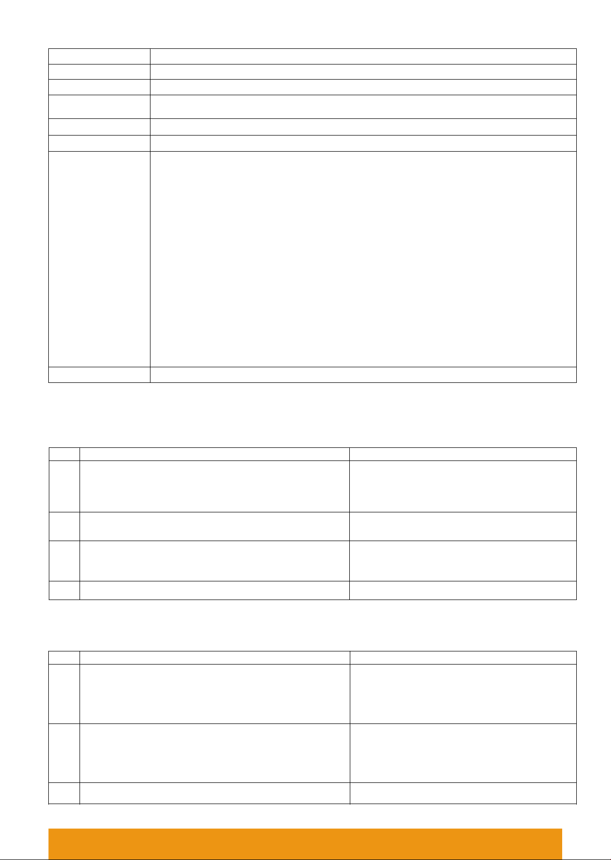
7.1.4 Remote control accessories installation instructions
Accessories include bracket 1pc, 3M foam sponge glue 1pc, screw 2pcs, expansion tube 2pcs.
There are 2 options for bracket installation:
1) Using screw and expansion tube make drilling installation (suitable for uneven and ash surface);
2) Using 3M foam sponge glue make free drilling installation (suitable for flat no ash surface).
P9 DIMMER AND REMOTE OPERATION

7.2 Dimmer Operation
7.2.1 Specification
Working temperature
-20-60℃
Supply voltage
DC12-24V
Output
1 channel
Static power consumption
<1W
Max. output current
25A
Max. output power
300W/12V; 600W/24V
Net weight
65g
External dimension
L103*W40*H24 mm
Gross weight
90g
Packing size
L140*W48*H35mm
Memory function
Yes
PWM frequency
2KHz (factory default),500Hz,1KHz,
4KHz, 7.8KHz, 15.6KHz
Max. output current
PWM<=2KHz: 25A
PWM=4/7.8KHz: 15A
PWM=15.6KHz: 10A
Max. output power
PWM<=2KHz:300W/12V; 600W/24V
PWM=4/7.8KHz:180W/12V;
360W/24V
PWM=15.6KH:120W/12V;
240W/24V
7.2.2 Control method
This product can be controlled by any compatible remote control as default; if unique-control is needed, please matching
the code before installation and using.
7.2.3 Connection port instruction
7.2.4 Direction for use
·Connect the load wire at first, followed by the power wire; Please ensure short circuit cannot occur between connecting wire
before turning on the power;
·Adopt rotary button, function as follows:
Clockwise rotation to brighten up brightness to 100% as the maximum; Counter clockwise rotation to dim down the brightness
to 0% as the minimum.
·PWM display: P005=500Hz; P010=1KHz; P020=2KHz (factory default); P040=4KHz, P078= 7.8KHz; P156=15.6KHz.
7.2.5 PWM Frequency Adjustment operation:
Press and hold the remote control “Set” for 5 seconds after switch off the dimmer by remote control (the dimmer is in off state)
within10 seconds, display will show as: P***. Means enter “PWM adjusting” state. Press Brightness +/- keys to adjust the PWM
frequency, pressing “Set” button again to save it after finish the setting operation. Then the dimmer returns to power on state
automatically.
7.2.6 Multiple Dimmer set-up
Each dimmer can send signal to another dimmer in the same zone (please see 7.1.3 for zone setting). It is recommended that
the distance between every dimmer is not greater than 10m.
DIMMER AND REMOTE OPERATION P10
20m LED strip
LED strip
LED strip
LED strip
LED strip
LED strip
LED strip
LED strip
220V AC 220V AC 220V AC
10m 10m 10m 10m 10m 10m 10m
Dimmer
Dimmer
Dimmer
Dimmer
Dimmer
Dimmer
Dimmer
Dimmer
24V DC 24V DC 24V DC
Power
supply Power
supply Power
supply
Remote
control

YOUR PREMIER SUPPLIER
www.emauxgroup.com
EMAUX WATER TECHNOLOGY CO., LTD
Other manuals for GL10
1
This manual suits for next models
15
Table of contents