emazys Z200 User manual

!
Z200 PV Analyzer
User Manual
emazys.com

Z200 PV Analyzer
User Manual
Contents
Page
1 Nomenclature 1
1.1 Warning signs . . . . . . . . . . . . . . . . . . . . . . . . . . . . . . . . . . . . . . . 1
1.2 Tips and recommendations . . . . . . . . . . . . . . . . . . . . . . . . . . . . . . . 1
2 Limited warranty and limitation of warranty 2
2.1 Warranty disclaimer . . . . . . . . . . . . . . . . . . . . . . . . . . . . . . . . . . . . 3
3 Unpacking and commissioning 4
3.1 Scope of delivery . . . . . . . . . . . . . . . . . . . . . . . . . . . . . . . . . . . . . 4
3.2 Commissioning . . . . . . . . . . . . . . . . . . . . . . . . . . . . . . . . . . . . . . 5
3.2.1 Battery....................................... 5
3.2.2 Control interface . . . . . . . . . . . . . . . . . . . . . . . . . . . . . . . . . 5
3.2.3 Cables ....................................... 6
4 Safety 7
4.1 Instrument self-check . . . . . . . . . . . . . . . . . . . . . . . . . . . . . . . . . . . 8
4.2 Labelling on instrument . . . . . . . . . . . . . . . . . . . . . . . . . . . . . . . . . 8
5 Introduction and operation 9
5.1 Front panel elements . . . . . . . . . . . . . . . . . . . . . . . . . . . . . . . . . . . 10
5.2 WiFi setup and Z200 WiFi basics . . . . . . . . . . . . . . . . . . . . . . . . . . . . . 11
5.3 Requirements for controller devices . . . . . . . . . . . . . . . . . . . . . . . . . . 12
5.3.1 Recommended internet browsers for controller devices . . . . . . . . . . . 12
5.3.2 Appearance of main Graphical User Interface - GUI . . . . . . . . . . . . . 13
6 Applications and measurements 14
6.1 Settings........................................... 15
6.2 Ground Fault . . . . . . . . . . . . . . . . . . . . . . . . . . . . . . . . . . . . . . . . 16
6.3 String Tester . . . . . . . . . . . . . . . . . . . . . . . . . . . . . . . . . . . . . . . . 18
6.4 VOC ............................................. 21
6.5 Disconnect . . . . . . . . . . . . . . . . . . . . . . . . . . . . . . . . . . . . . . . . . 22
6.6 Timer ............................................ 24
6.7 Module test . . . . . . . . . . . . . . . . . . . . . . . . . . . . . . . . . . . . . . . . 25
6.8 Tone generator and pickup . . . . . . . . . . . . . . . . . . . . . . . . . . . . . . . . 27
7 Calibration 28
8 Storage and disposal 29
8.1 Storage........................................... 29
8.2 Disposal .......................................... 29
i

Z200 PV Analyzer
User Manual
1 Nomenclature
1.1 Warning signs
Please note that the manual uses the following safety instructions. The safety instructions should
be followed carefully. Failure to do so may cause personal injury or irreparable damage to the
equipment.
WARNING.
Personal injury / death. A situation of use of a technical na-
ture or the like which may cause injury or death.
WARNING.
Personal injury / death. Risk of electrical shock.
CAUTION.
Damage to the machine or accessory. A situation of use of
a technical nature or the like, which can cause damage to the
machine or accessories.
NOTICE.
Important information. A situation of use of a technical na-
ture or the like, which is very important
1.2 Tips and recommendations
Please note that the manual uses the following information instruction.
INFORMATION.
Provides useful tips and recommendations and provides in-
formation on how to use the product efficiently and without
interruptions.
1

Z200 PV Analyzer
User Manual
2 Limited warranty and limitation of warranty
Each EmaZys product is warranted to be free from defects in material and workmanship under
normal use and service. The warranty period is one year and begins on the date of shipment.
Parts, product repairs, and services are warranted for 90 days. This warranty extends only to
the original buyer or end-user customer of a EmaZys authorized reseller, and does not apply
to fuses, disposable batteries, or to any product which, in EmaZys’s opinion, has been misused,
altered, neglected, contaminated, or damaged by accident or abnormal conditions of operation
or handling. EmaZys warrants that software will operate substantially in accordance with its
functional specifications for 90 days and that it has been properly recorded on non-defective
EmaZys does not warrant that software will be error free or operate without interruption.
EmaZys authorized resellers shall extend this warranty on new and unused products to end-
user customers only but have no authority to extend a greater or different warranty on behalf
of EmaZys. Warranty support is available only if product is purchased through a EmaZys autho-
rized sales outlet or Buyer has paid the applicable international price. EmaZys reserves the right
to invoice Buyer for importation costs of repair/replacement parts when product purchased in
one country is submitted for repair in another country.
EmaZys’s warranty obligation is limited, at EmaZys’s option, to refund of the purchase price, free
of charge repair, or replacement of a defective product which is returned to a EmaZys autho-
rized service center within the warranty period.
To obtain warranty service, contact EmaZys service center on E-mail:
service center, with a description of the difficulty, postage and insurance prepaid (FOB Desti-
nation). EmaZys assumes no risk for damage in transit. Following warranty repair, the product
will be returned to Buyer, transportation prepaid (FOB Destination). If EmaZys determines that
failure was caused by neglect, misuse, contamination, alteration, accident, or abnormal condi-
tion of operation or handling, including over-voltage failures caused by use outside the products
specified rating, or normal wear and tear of mechanical components, EmaZys will provide an es-
timate of repair costs and obtain authorization before commencing the work. Following repair,
the product will be returned to the Buyer transportation prepaid and the Buyer will be billed for
the repair and return transportation charges (FOB Shipping Point).
THIS WARRANTY IS BUYER’S SOLE AND EXCLUSIVE REMEDY AND IS IN LIEU OF ALL OTHER WAR-
RANTIES, EXPRESS OR IMPLIED, INCLUDING BUT NOT LIMITED TO ANY IMPLIED WARRANTY OF
MERCHANTABILITY OR FITNESS FOR A PARTICULAR PURPOSE. EMAZYS SHALL NOT BE LIABLE
FOR ANY SPECIAL, INDIRECT, INCIDENTAL, OR CONSEQUENTIAL DAMAGES OR LOSSES, INCLUD-
ING LOSS OF DATA, ARISING FROM ANY CAUSE OR THEORY.
Since some countries or states do not allow limitation of the term of an implied warranty, or
exclusion or limitation of incidental or consequential damages, the limitations and exclusions of
this warranty may not apply to every buyer. If any provision of this Warranty is held invalid or
unenforceable by a court or other decision-maker of competent jurisdiction, such holding will
not affect the validity or enforceability of any other provision.
2

Z200 PV Analyzer
User Manual
2.1 Warranty disclaimer
PV Analyzer Z200 is warranted for 12 months from the reception. The warranty does not cover
the battery. There is no warranty on the device, if you use other cables than the supplied. The
warranty will be invalid if the product is damaged due to any of the following:
•Neglect to follow the User Manual
•Use of the product for purposes for which it was not intended
•Natural wear
•Incorrect fitting
•Mechanical or technical alterations
•Use of unauthorized spare parts
3

Z200 PV Analyzer
User Manual
3 Unpacking and commissioning
3.1 Scope of delivery
The PV Analyzer Z200 is delivered in a cardboard box.
INFORMATION.
If you use knives or sharp objects when unpacking, please
observe great care.
After unpacking, make sure that you have received all parts ordered. Accessories and special
items may have been ordered as well, so please check with your purchase order and invoice,
that nothing is missing. If you have not received all parts, please contact EmaZys or your local
distributor.
Z200 PV Analyzer std. kit.
1. Z200 PV Analyzer
2. Tone pickup
3. RRC2054 Battery
4. RRC-SMB-MBC Standard Battery Charger
5. Banana-MC4 PV+ testing lead
6. Banana-MC4 PV- testing lead
7. Banana Croc. GND testing lead
Note: The picture shows the std. Z200 PV Analyzer testing kit. A range of different acces-
sories can be supplied from EmaZys - please go to EmaZys.com and see what we can offer. We
recommend to also buy and use the tone pickup, when ordering the Z200 PV Analyzer kit. The
tone pickup will enable more fault localisation functionality in your instrument.
4

Z200 PV Analyzer
User Manual
3.2 Commissioning
3.2.1 Battery
Prior to start-up please check that the RRC2054 battery is fully charged. The battery can be
charged using the charger that comes with the instrument. See battery specifications in the
section ”Technical data”.
3.2.2 Control interface
The control interface is separated from the main instrument box in a wireless manner, and you
may use a smart device with WiFi transceiver, with an internet browser as controller device. The
front panel itself only includes instrument status LEDs, the ON-OFF/WAKE UP button, battery
acces, and WiFi antenna.
5
Z200 PV Analyzer
User Manual
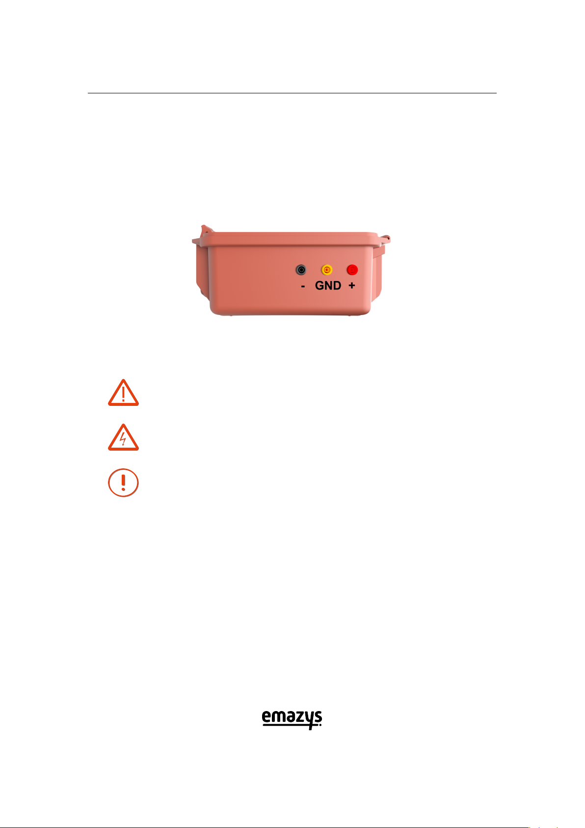
3.2.3 Cables
Connect the supplied cables to the instrument. The red wire is connected to the Red (+) connec-
tion socket, the black wire is connected to the Black (-) connection socket and the Yellow/Green
wire is connected to GND. Different solar PV modules may use different connectors, than sup-
plied with the Z200 PV Analyzer std. kit. If you need other types of adaptors, please contact
EmaZys or your local distributor.
Make sure to connect the inputs correctly on the Z200.
(Cables are all colored accordingly)
WARNING.
Personal injury /death. Make sure cables used to connect
the instrument to photovoltaic modules and strings are CAT III,
1000V compliant.
WARNING.
Personal injury / death. Risk of electrical shock.
CAUTION.
Damage to the machine or accessory. It is not recommended to
use cables other than the supplied. The instrument’s warranty is
no longer valid if other types of cables are used.
6

Z200 PV Analyzer
User Manual
4 Safety
Before carrying out measurements with PV Analyzer Z200, you must ensure that:
•there is sufficient space to operate the instrument
•the necessary tools are present on the site
•the operator has a general knowledge of PV modules (photovoltaic modules) and is trained
to work in high voltage environments
•the instrument is correctly connected
•the instrument and the measurement cables are in good condition. Check that the cables
are not cracked or damaged in any way.
NOTICE.
•The PV Analyzer Z200 and the User Manual are intended for
use by adequately trained personnel.
•Before use, the operator must have read the user manual.
•The User manual must be kept near the instrument.
WARNING.
•PV module measurements are performed in high voltage
areas. Always use approved safety equipment designed for
high voltage installations.
•If subjected to an electrical shock, you must seek medical
advice, even if you feel well. Some potentially harmful ef-
fects may not occur until several hours after exposure.
CAUTION.
•Exercise caution in use.
•The PV Analyzer Z200 should be used wherever possible in
a dry environment.
•The instrument’s lid should always be closed during long-
term measurements. Make sure to mark up the measuring
site.
7

Z200 PV Analyzer
User Manual
4.1 Instrument self-check
The PV Analyzer Z200 also conducts self-check procedures of internal HW components that are
critical to the safety of the operator. Self-check procedures are carried out as part of all measure-
ment features and on all involved critical HW components. Failures detected could be temporary
(excessive voltages, excessive currents or overheating during measurements) or permanent (e.g.
malfunction of a HW component). In both cases, a pop-up window will appear to instruct the op-
erator on how to proceed if a failure occurs. Most often a power OFF/ON cycle will be sufficient
to fully analyse and in most cases also clear temporary errors.
4.2 Labelling on instrument
In the lid of the instrument is placed a Quick guide sticker that shows how to get started. You will
also find a number symbols for safety etc. Please read and understand these symbols before
you start working with the instrument.
Caution risk of electrical shock.
Risk of personal injury / death.
Waste Electrical and Electronic Equipment Directive.
CE marking - Communautes Europeennes.
Double insulated.
RoHS Restriction of Hazardous Substances.
8

Z200 PV Analyzer
User Manual
5 Introduction and operation
The PV Analyzer Z200 is a portable and battery powered instrument used to detect and locate
faults in strings of series connected photovoltaic modules.
INFORMATION.
All Z200 analysis algorithms, assumes that the instrument is
connected to a series string of solar PV modules. Correct fault
position estimation can hence not be guaranteed, if the Z200 is
connected to parallel coupled solar PV module strings.
Specifically, the instrument has the following features and measurement applications:
1. Measure position of a single ground fault in a PV string
2. Measure position of a single disconnect in PV strings
3. PV string impedance curves (health and degradation check)
4. PV string series resistance RS
5. PV string string open circuit voltage VOC
6. PV string string short circuit current SC
7. PV system isolation resistance RISO
8. PV module voltage
9. PV module bypass diode check
10. PV module shunting resistance (module/cell degradation)
11. Integrated timer for periodic faults
12. Tone generator and tone tracer pickup
13. Build in PDF report generator
The instrument is connected to the string terminals e.g. at the string inverter or combiner
box and also to the ground reference for the PV installation.
Once connected and activated, it will perform impedance spectroscopy between any two of the
three connected terminals, as well as measure the terminal voltages and currents flowing un-
der various DC loads introduced by the instrument. By combining the results from these various
measurements using the on-board computer, critical faults in the system can be defined and po-
sitioned.
9

Z200 PV Analyzer
User Manual
5.1 Front panel elements
In the illustrations below, you will find a description of each element found on the front panel
of the Z200 PV Analyzer. The tables below show sections of the front panel seen in Figure 1.
Figure 1: The Z200 PV Analyzer front panel.
The operating state of the instrument is indicated by 3 colored
light emitting diodes (LEDs). The green diode is on when the in-
strument is turned on. The yellow diode indicates that the WiFi
antenna is ready to transmit and receive data. The red LED will in
general blink when the instrument is busy with either measure-
ments or analysis
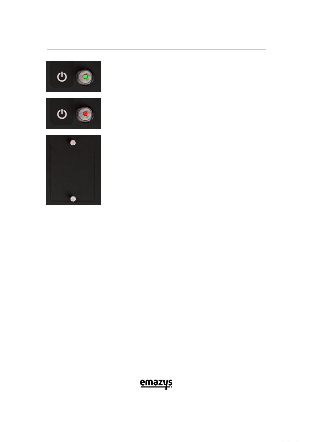
Placed on the middle of the front panel we find the ON/OFF
switch. When the instrument is turned on a small LED in the but-
ton will emit green light. The ON/OFF button also controls the
”Timer” application. This application is described in detail in the
Timer section.
The instrument USB antenna is found above the ON/OFF but-
ton. Please never remove this antenna. It is paired to the
instrument, and EmaZys support is needed to install a new
antenna.
The ON/OFF button is in the OFF state, and the instrument is
turned off.
10
Z200 PV Analyzer
User Manual
The ON/OFF button is in the ON state, and the instrument is
turned on.
The ON/OFF button is in the WAKE UP state, and the instrument
is in the timer mode.
The Z200 PV Analyzer battery solution is based on a rechargeable
RRC 2054 Li-ion battery, that can be reached from the front panel
by loosening the two finger screws. The battery cover must be
mounted at all times, unless when the battery is being replaced.
5.2 WiFi setup and Z200 WiFi basics
You will communicate with the PV Analyzer Z200 through a browser window at all time.
1. After turning on the instrument, the internal computer will set up a WiFi hotspot (local
wireless network) that can be connected with other WiFi devices, so make sure that WiFi
on your preferred smart device (smartphone, tablet or laptop) is enabled.
2. The name of the hotspot access point will be in the form: ”Z200-xxxx-xxxx”, where x rep-
resents unique numbers for every Z200 hotspot. Once you have found the hotspot simply
connect using the password: Xoplag10.
3. Open your internet browser (e.g. google Chrome) and type: ”z200/” in the URL bar. If
you are already connected to the internet by other means, you have to type ”192.168.4.1”
instead, as this signifies to your device not to look up the Z200 through a DNS server, but
only find it within the local WiFi network itself.
4. When using a new browser to access the Z200 for the first time, it might be necessary to
enable PopUps for the Z200 homepage, in order to allow it to store PDF reports from your
subsequent measurements. This is e.g. done within Chrome by clicking on the ”No PopUp”
icon, that appears to the right of the URL-address bar AFTER creating the first PDF report
(It is only needed the first time you generate a report).
5. Optional: With Chrome it is possible to make a shortcut to the Z200 homepage, so you can
open up directly to the Z200 with an icon of its own. Go to the Z200 homepage, and open
the menu to the right of the URL address bar and tap on ”Add to home Screen”.
11
Z200 PV Analyzer
User Manual
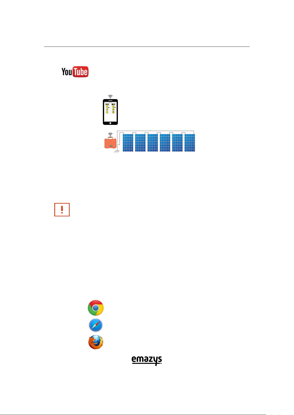
INSTRUCTION
At the following URL youtube.com/EmaZys a number of in-
structional videos can be found. Also, EmaZys.com is frequently
updated with relevant technical guidance.
Figure 2: Once the Z200 is correctly connected to the string of photovoltaic modules, it can per-
form full string analysis controlled from the WiFi connected device.
NOTICE.
1. If the Z200 has been disconnected or turned off, you need
to reconnect to the Z200 hotspot.
2. If you get out of reach of the Z200, it may also be necessary
to reconnect your device with the Z200, depending on the
availability of other nearby networks within reach of your
device.
5.3 Requirements for controller devices
The controller device may be a smartphone, a tablet computer or a PC / MAC. It is left to the user
to choose his preferred device. In some situations a smartphone may be sufficient, and in other
cases when evaluating data, a device with a larger screen may be preferred.
5.3.1 Recommended internet browsers for controller devices
Z200 PV Analyzer has been optimized for use with the following internet browsers.
Google Chrome browser
Apple Safari browser
Firefox browser
12
Z200 PV Analyzer
User Manual
Figure 3: An illustration showing the different options for choice of controller device for the Z200
PV Analyzer. The controller device may be a smartphone, a tablet computer, a PC / MAC or even
other unconventional devices.
Please note that using other browsers, such as e.g. Microsoft Internet explorer, is not recom-
mended and full functionality can not be guaranteed in such cases.
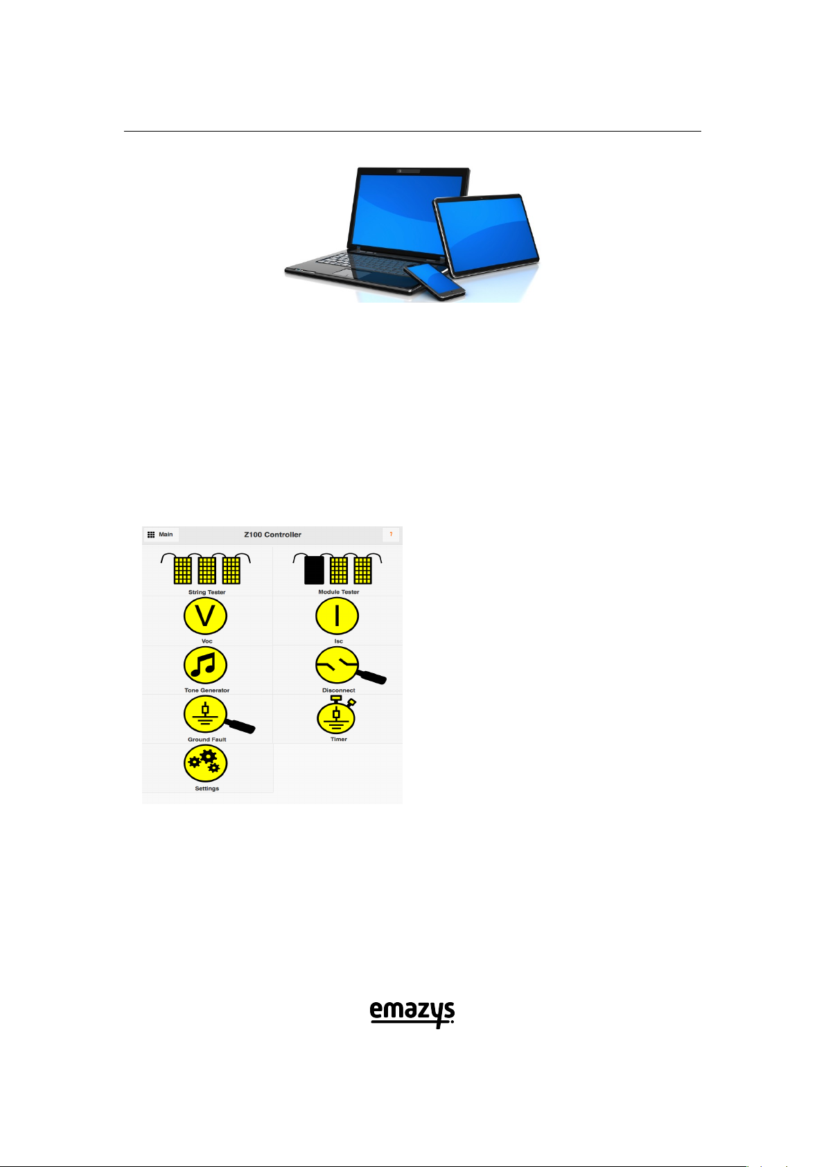
5.3.2 Appearance of main Graphical User Interface - GUI
Below we see screenshots of the main Graphical User Interface (GUI). The GUI is basically a sim-
ple website, hosted on the Z200 PV Analyzer.
Main menu User Interface. This
screen will appear in your browser
window when connected with the
Z200 WiFi hotspot.
1) The Main button leads back to
this main GUI screen from any
other page in the controller inter-
face.
2) The charging state of the battery
is seen in the upper middle part of
the GUI. In this example we have 44
%capacity left.
3) Press the red question mark at
any page in the controller interface,
to read a brief summary of the cho-
sen application.
13

Z200 PV Analyzer
User Manual
6 Applications and measurements
Some rudimentary control and assessment of the light reaching the string and individual PV
modules is necessary. I.e. in order to accurately detect and localize ground faults, and discon-
nects in cables and connectors, all the modules in the string under test need to be illuminated
by at least 100 W
m2. The most accurate results are obtained when the irradiation level is steady
throughout your measurement. This is also the case if you want to estimate the overall string
series resistance RS. When checking the health state of module bypass diodes it is also neces-
sary with ambient sunlight intensity at each module of at least 100 W
m2. Please note that testing
the health state of the diodes in a specific PV module in the string, requires blocking the sunlight
from reaching that module. If RPof the string or a subset of the string down to individual cells
or modules needs to be measured the sunlight needs again to be blocked from reaching the PV
cells or modules being tested, however this can be achieved by measuring at nighttime (I.e. RP
of the entire string).
14
Z200 PV Analyzer
User Manual
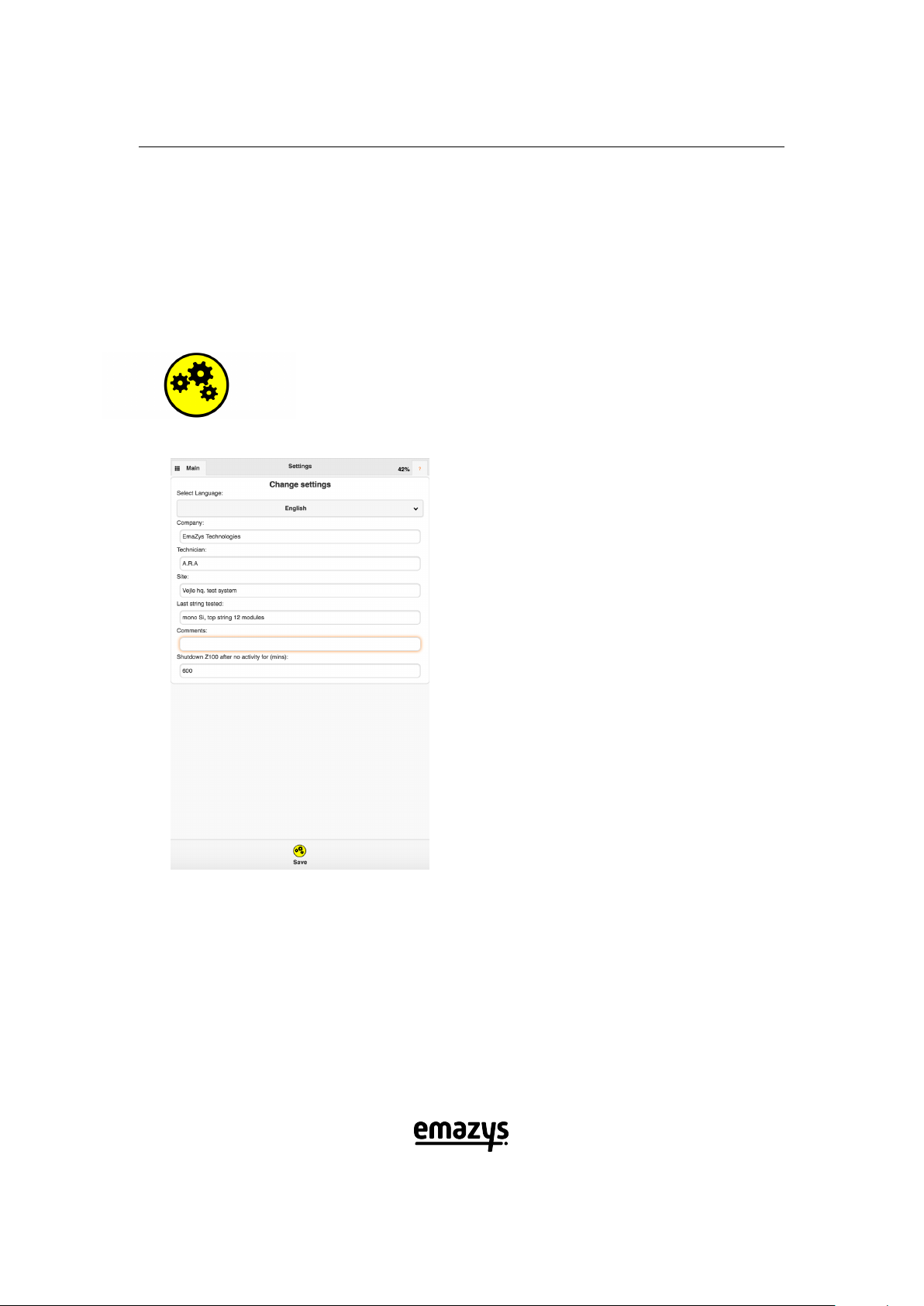
6.1 Settings
Before starting the actual measurements, it is advised to enter information about the site you
are working on. This information will be transferred to the PDF report template found in some
other applications e.g. ”Ground Fault”. The test results from the various measurements, can
be transferred into individual PDF reports, which in turn can be downloaded to your preferred
device, for documentation purposes.
APPLICATION.
Settings is used to enter basic information about your
company, name of technician, the site you are working
on, and other relevant information for documentation
purposes. The information entered will go in the PDF
report generated by the instrument.
Select Settings in the main menu.
Type in your company name, name
of technician and site/location. For
each measurement report, you
have the choice of adding addi-
tional information that might be
helpful in the subsequent analysis
of your results. When the entry
is complete, just press Save. The
entered data is then included in
the reports made from the various
measurements.
15

Z200 PV Analyzer
User Manual
6.2 Ground Fault
APPLICATION.
This application is used to measure the isolation of
the PV string towards ground. If poor isolation is found,
the instrument will attempt to position the fault.
First enter the number of PV modules using the + and -
keys. The measurement will take 45-60 seconds. In the Re-
sults window the measured RISO together with the string
VOC are returned. After the measurement is done, you can
download a PDF report with the results to your device for
documentation purposes. Simply press the Generate re-
port button, and follow the instructions in the GUI.
16

Z200 PV Analyzer
User Manual
NOTICE.
•Due to the inherent uncertainty of the fault localiza-
tion method and due to the possibility of multiple or
distributed faults, it is highly recommended to verify
a fault position by bypassing a given faulty module
or cable segment with a known good cable and redo
the measurement to ensure good isolation BEFORE
repairing the string e.g. replacing a cable segment or
PV module.
•It is good practice to verify correct connection of the
string to the instrument AND sufficient illumination
of modules (>100 W
m2) by comparing the measured
PV voltage with the expected voltage (Number of
modules multiplied by the Voc of each module in the
string).
•The measurement analysis assumes that modules in
the string are producing evenly. If a fault is not found
accurately, it may point to additional or other prob-
lems and the user is advised to run a String test.
17
Table of contents


