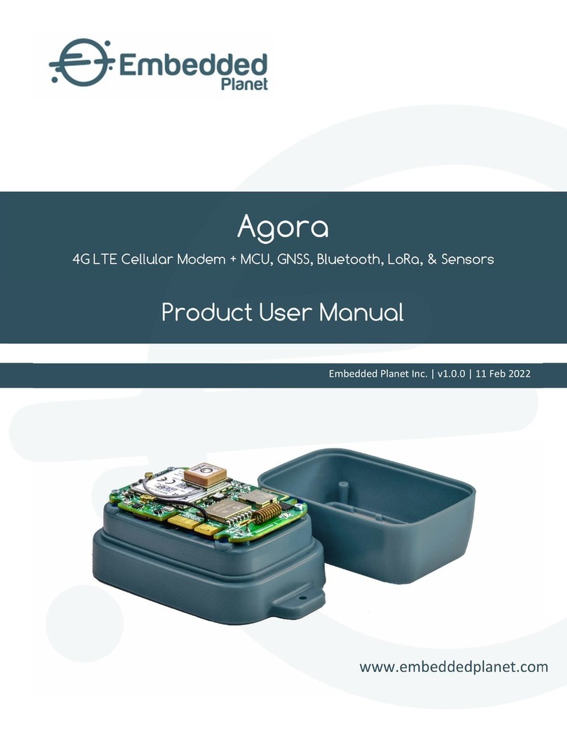
Embedded Planet epConnected Asset Operational manual

www.embeddedplanet.com
Embedded Planet Inc. | v1.0.1 | 05 APR 2022
epConnected Asset
4G LTE-M Cellular Modem + GNSS Tracking, Bluetooth, & Sensors
Product User Manual

Embedded Planet, Inc.
epConnected Asset | Product User Manual
Document Version: 1.0.0 | 26 Jan 22
Embedded Planet, Inc. | 31225 Bainbridge Rd Suite N, Solon, OH 44139 | 216-245-4180 | www.embeddedplanet.com | Page 1 of 37
About This Manual
The epConnected Asset User Manual provides detailed information encompassing the design,
description, and integration of the epConnected Asset device. For elaboration on drawings, software, or other
specific product details there may be other sources of information to which this document points as reference.
For the latest documentation, including document & certification updates, please always refer to the Embedded
Planet documentation page: https://www.embeddedplanet.com/product-documentation
Product Web Page
The epConnected Asset product page by Embedded Planet provides description & resources related to
this product. This page can be located at https://www.embeddedplanet.com/connected-asset

Embedded Planet, Inc.
epConnected Asset | Product User Manual
Document Version: 1.0.0 | 26 Jan 22
Embedded Planet, Inc. | 31225 Bainbridge Rd Suite N, Solon, OH 44139 | 216-245-4180 | www.embeddedplanet.com | Page 2 of 37
Contents
1. Introduction...................................................................................................................................................... 4
2. Orderable Part Numbers ..................................................................................................................................5
3. Additional Resources .........................................................................................................................................5
4. Feature Callouts ................................................................................................................................................6
4.1. Feature Callouts | Connectors / Interfaces...................................................................................................6
4.2. Feature Callouts | Key Board Components (Top) ..........................................................................................7
4.3. Feature Callouts | Key Board Components (Bottom) ......................................................................................8
5. Block Diagram ....................................................................................................................................................9
6. Device Specifications ........................................................................................................................................10
7. Chronos Module................................................................................................................................................ 11
8. MCU ................................................................................................................................................................... 11
9. Sensors .............................................................................................................................................................12
9.1. Sensors | 3-Axis Accelerometer (U15)..............................................................................................................12
9.2. Sensors | 6-Axis IMU (U6) ..................................................................................................................................13
9.3. Sensors | 9-Axis IMU (U7) ................................................................................................................................. 14
9.4. Sensors | Barometer / Altimeter (U8)..............................................................................................................15
9.5. Sensors | Temperature & Humidity (U14) ........................................................................................................16
10. Indicators..........................................................................................................................................................17
10.1. Indicators | RGB LED .........................................................................................................................................17
10.2. Indicators | Battery Status LEDs ..................................................................................................................17
11. Memory .............................................................................................................................................................18
12. Power ................................................................................................................................................................18
12.1. Power | Battery.................................................................................................................................................18
12.2. Power | Battery Charging ............................................................................................................................19
12.3. Power | Battery Monitor ...............................................................................................................................19
12.4. Power | USB Connector ................................................................................................................................19
12.5. Power | Battery Connector .........................................................................................................................20
12.6. Power | nRF52840 Power Control ................................................................................................................20
12.7. Power | Sensor Power Control....................................................................................................................20
12.8. Power | Chronos Power Control ..................................................................................................................21
12.9. Power | Power Tree......................................................................................................................................21
13. Programming, Debugging, & Development......................................................................................................21
14. Pinouts .............................................................................................................................................................22
14.1.MCU Pinout.......................................................................................................................................................22
14.2. Mini-Tectonic Edge™ Pinout ........................................................................................................................24
14.3. Expansion Header Pinout (J5).....................................................................................................................25
15. Antennae .........................................................................................................................................................26
15.1. Antennae | Cellular Antenna .........................................................................................................................26
15.2. Antennae | GNSS Antenna...........................................................................................................................27
16. Electrical Specifications...................................................................................................................................27
16.1. Absolute Maximum & Minimum Ratings...........................................................................................................27
16.2. Recommended Operating Conditions ........................................................................................................27
17. Mechanical Specifications................................................................................................................................28
17.1. Physical Parameters ........................................................................................................................................28
17.2. Mechanical Drawings...................................................................................................................................28

Embedded Planet, Inc.
epConnected Asset | Product User Manual
Document Version: 1.0.0 | 26 Jan 22
Embedded Planet, Inc. | 31225 Bainbridge Rd Suite N, Solon, OH 44139 | 216-245-4180 | www.embeddedplanet.com | Page 3 of 37
17.3. Environmental Specifications ..................................................................................................................... 33
18. Regulatory Information ...................................................................................................................................33
18.1. Cellular Certifications..................................................................................................................................... 33
18.2. RoHS Compliance ......................................................................................................................................... 33
18.3. Interferance Statement..............................................................................................................................34
18.4. FCC and ISED Compliance ...........................................................................................................................34
18.5. Wireless Notice............................................................................................................................................34
18.6. Antenna Notice: FCC ...................................................................................................................................35
18.7. Antenna Notice: ISED ...................................................................................................................................35
18.8. End-Product Labeling Requirements ..........................................................................................................36
18.9. FCC Additional Testing, Part 15 Subpart B Disclaimer.................................................................................36
19. Revision History ................................................................................................................................................37
Table 1 –Part Number Configurator.......................................................................................................................................5
Table 2 - Board connectors.....................................................................................................................................................6
Table 3 –Key board components ...........................................................................................................................................7
Table 4 –Key Board Components (Bottom) ...........................................................................................................................8
Table 5 –Device specifications .............................................................................................................................................10
Table 6 –RGB LED pin details ...............................................................................................................................................17
Table 7 –MCU Pinout ...........................................................................................................................................................22
Table 8 –Mini-tectonic edge™ pinout..................................................................................................................................24
Table 9 –Mini-Tectonic Edge™ Resistor options..................................................................................................................25
Table 10 –Expansion Header pinout ....................................................................................................................................25
Table 11 –Absolute maximum & minimums........................................................................................................................27
Table 12 –Recommended operating conditions..................................................................................................................27
Table 13 –Physical parameters ............................................................................................................................................28
Table 14 –Environmental specifications ..............................................................................................................................33
Table 15 –FCC max gain by band..........................................................................................................................................35
Table 16 –ISED max gain by band ........................................................................................................................................35
Table 17 –revision history....................................................................................................................................................37

Embedded Planet, Inc.
epConnected Asset | Product User Manual
Document Version: 1.0.0 | 26 Jan 22
Embedded Planet, Inc. | 31225 Bainbridge Rd Suite N, Solon, OH 44139 | 216-245-4180 | www.embeddedplanet.com | Page 4 of 37
1. Introduction
The epConnected Asset is a GNSS asset tracker with cellular connectivity designed as part of Embedded Planet’s
epConnect ecosystem. The epConnected Asset takes advantage of the 4G LTE CAT M1 cellular connection and GNSS
capability provided by Embedded Planet’s Chronos module. An onboard MCU provides the processing control to
leverage the attached Chronos module & on-board sensors. Device sensors include a barometer/altimeter, a 3-axis
accelerometer, a 6-axis IMU, and a 9-axis IMU. An ultra-low power timer is present to enable long battery life
applications. Rechargeable LiPo battery compatibility is also supported. Acquired data can be stored in the provided
on-board flash memory. Data can be transferred over the cellular connection hosted by the Chronos module,
through the Bluetooth connection of the MCU, or via USB. A micro-B USB connector is present for battery charging
& data transfer. Configuration of the epConnected Asset device can be performed over the Bluetooth connection.
An onboard RGB LED is provided for user feedback through the programmed application.

Embedded Planet, Inc.
epConnected Asset | Product User Manual
Document Version: 1.0.0 | 26 Jan 22
Embedded Planet, Inc. | 31225 Bainbridge Rd Suite N, Solon, OH 44139 | 216-245-4180 | www.embeddedplanet.com | Page 5 of 37
2. Orderable Part Numbers
This table shows the flexibility of possible device configurations. Availability of specific configurations is
contingent on current stocking & ordering conditions. Please contact Embedded Planet sales to ask about a
configuration not found in the Embedded Planet shop: sales@embeddedplanet.com. The Embedded Planet shop is
hosted at shop.embeddedplanet.com.
TABLE 1 –PART NUMBER CONFIGURATOR
Option
Designator
Description
1
Battery Connector
N
None
J
JST S2B-PH-SM4-TB(LF)(SN)
2
Battery Charger
N
None
L42
Lithium 4.2V
3
USB Connector
N
None
B
USB Micro-B
4
Flash Memory
N
None
16
16MB
5
Inertial Measurement
N
None
3
3-axis accelerometer
6
3-axis accelerometer, 3-axis gyroscope
9
3-axis accelerometer, 3-axis gyroscope, 3-axis
magnetometer
6
Barometer
N
None
M
MPL3115A2
7
Temperature/Humidity
N
None
S
Si7021-A20
8
Low-power Timer
N
None
T
TPL5110
9
GNSS
N
None
G
GNSS
10
Cellular
N
None
M1
4G LTE CAT M1
An example configuration for the epConnected Asset device is 281B-NL42B163NNNGM1 as shown above. For
ordering, please refer to the details on the Embedded Planet shop website for confirmation on configuration
specifics: https://shop.embeddedplanet.com
3. Additional Resources
•Chronos module:
https://www.embeddedplanet.com/chronos
•epConnected Asset:
https://www.embeddedplanet.com/connected-asset
•Embedded Planet Documentation:
https://www.embeddedplanet.com/product-documentation

Embedded Planet, Inc.
epConnected Asset | Product User Manual
Document Version: 1.0.0 | 26 Jan 22
Embedded Planet, Inc. | 31225 Bainbridge Rd Suite N, Solon, OH 44139 | 216-245-4180 | www.embeddedplanet.com | Page 6 of 37
4. Feature Callouts
4.1. Feature Callouts | Connectors / Interfaces
TABLE 2 - BOARD CONNECTORS
Category
Reference Designator
Component Type
Description / Purpose
Connector
J3
JST / Battery
For use with external LiPo battery
Connector
J2
Micro-USB
Battery charging and data transfer
Connector
J5
Expansion Header
SPI, GPIO, 3.0V I/O ref, battery voltage
Connector
Mini-Tectonic Edge™
Board Edge / Finger
Mini-Tectonic Edge™ for programming
J3: Battery
J2: USB
J5: Expansion
Header
J3: Mini-
Tectonic
Edge

Embedded Planet, Inc.
epConnected Asset | Product User Manual
Document Version: 1.0.0 | 26 Jan 22
Embedded Planet, Inc. | 31225 Bainbridge Rd Suite N, Solon, OH 44139 | 216-245-4180 | www.embeddedplanet.com | Page 7 of 37
4.2. Feature Callouts | Key Board Components (Top)
TABLE 3 –KEY BOARD COMPONENTS
Category
Reference
Component Type
Description / Purpose
Antenna
1
BLE antenna
BLE connectivity for the nRF52840
Power
2
Battery through-holes
Alternate option to the JST connector
LED
3
RGB LED
Useful as a status indicator or for debug
LED
4
Red/Green LEDs
Indicate battery charging status
MCU
5
nRF52840
Main processor that controls the system
Antenna
6
GNSS antenna
Onboard option for GNSS antenna
Flash
7
External NOR Flash
Dedicated flash memory for nRF52840
Antenna
8
Cellular antenna
Onboard option for Cell antenna
1: Onboard
BLE antenna
5: nRF52840
7: External Flash
8: Onboard Cell
antenna
6: Onboard GNSS
antenna
3: RGB
LED
2: Battery
through-hole
option
4: Red/Green battery
charge status indicators

Embedded Planet, Inc.
epConnected Asset | Product User Manual
Document Version: 1.0.0 | 26 Jan 22
Embedded Planet, Inc. | 31225 Bainbridge Rd Suite N, Solon, OH 44139 | 216-245-4180 | www.embeddedplanet.com | Page 8 of 37
4.3. Feature Callouts | Key Board Components (Bottom)
TABLE 4 –KEY BOARD COMPONENTS (BOTTOM)
Category
Reference
Component Type
Description / Purpose
Label
1
Label
Serialization & board identification
Modem
2
Chronos modem module
Cellular/GNSS connectivity modem
LED
3
Red LED
Status/debug indication
SIM
4
Nano-SIM
SIM usage (default)
SIM
5
eSIM (embedded SIM)
SIM usage (optional)
Cell module
6
Telit cellular module
Cellular/GNSS connectivity
1: Serial Number /
Board ID label
2: Chronos modem
8: Chronos
Telit module
3: Chronos LED
6: Chronos SIM
card holder
7: Chronos
eSIM pad
4: Cellular U.FL
connector
5: GNSS U.FL
connector

5. Block Diagram

6. Device Specifications
TABLE 5 –DEVICE SPECIFICATIONS
Feature/Specification
Description
Cellular Capabilities
Cellular Technologies: LTE-M (LTE CAT M1)
SMS: over NAS
Lower power modes: PSM, eDRX
Operating Frequencies: 699MHz to 1980MHz
Cellular Operating Mode: Half-duplex FDD
RF Output Power: Up to +20dBm (Power Class 5)
Internet Protocols
IPv4/IPv6 stack with TCP and UDP protocols
TLDS/DTLS
LTE CAT M1 Specification
Bands: B1, B2, B3, B4, B5, B8, B12, B13, B18, B19, B20, B25, B26, B27, B28, B66, B71, B85
RX Sensitivity CAT M1: -102.2 to -107.5 dBm depending on band
Uplink: up to 1Mbps
Downlink: up to 588kbps
SIM
Removable: 4FF (nano) SIM card slot
Soldered down: MFF2
Internal: Telit simWISE™
Cellular Certifications
PTCRB: Complete (Chronos)
AT&T: Complete (Chronos)
Verizon: Complete (Chronos)
GNSS Specifications
Constellations: GPS, GLONASS, BeiDou, Galileo, QZSS
Tracking Sensitivity: -159dBm
Navigation Sensitivity: -155dBm
Cold Start Sensitivity: -144dBm
Power Supply
For battery charging: 3.75Vdc to 5.5Vdc into J2 (USB connector)
For device operation: 3.2Vdc-4.2Vdc into J3 (JST battery connector/through-holes)
3.7Vdc nominal
Dimensions
Fully populated board: 46.4mm x 38.4mm x 12.67mm (1.83in x 1.51in x 0.50in)
Environmental
Operating Temperature Range: -40°C to +85°C
Storage Temperature Range: -40°C to +85°C
Humidity Range: 20% RH to 90% RH

Embedded Planet, Inc.
epConnected Asset | Product User Manual
Document Version: 1.0.0 | 26 Jan 22
Embedded Planet, Inc. | 31225 Bainbridge Rd Suite N, Solon, OH 44139 | 216-245-4180 | www.embeddedplanet.com | Page 11 of 37
7. Chronos Module
Chronos is Embedded Planet’s custom 4G LTE CAT M1 embedded cellular modem. The epConnected Asset
device leverages the abilities of Chronos for its cellular and GNSS connectivity. In the default configuration of the
epConnected Asset board Chronos is already included as a board-mounted component. Details for Chronos itself can
be found here: https://www.embeddedplanet.com/product-documentation/#chronos
Chronos provides two U.FL connectors; one for a cellular antenna and one for a GNSS antenna. Both of these
connectors are routed to the epConnected Asset board through U.FL-to-U.FL cables. Section 15 (Antennae) goes into
further detail on these connections.
8. MCU
The MCU on the epConnected Asset is Nordic’s nRF52840 (U1). Details of this MCU can be found here:
https://www.nordicsemi.com/Products/Low-power-short-range-wireless/nRF52840
The nRF52840 is used to control power to the on-board sensors and to Chronos using GPIO. The sensors are
connected to the nRF52840 on the I2C bus. The Chronos module is connected to the nRF52840 via UART and GPIO.
The ultra-low power timer’s DONE pin is controlled by GPIO, allowing the nRF52840 to stay on for an arbitrary
amount of time once the timer has applied power to the nRF52840. The external flash memory is connected to the
nRF52840’s QSPI peripheral. The battery monitor is connected to an ADC channel on the nRF52840. For the MCU
pinout, refer the section of this report titled, “MCU Pinout” under “Pinouts”.
U1: nRF52840
MCU
Chronos
embedded modem

Embedded Planet, Inc.
epConnected Asset | Product User Manual
Document Version: 1.0.0 | 26 Jan 22
Embedded Planet, Inc. | 31225 Bainbridge Rd Suite N, Solon, OH 44139 | 216-245-4180 | www.embeddedplanet.com | Page 12 of 37
9. Sensors
The epConnected Asset board is designed to accommodate up to 5 onboard sensors. The following are available:
•3-Axis Accelerometer (U15)
•6-Axis IMU (U6)
•9-Axis IMU (U7)
•Barometer/Altimeter (U8)
•Temperature & Humidity (U14)
9.1. Sensors | 3-Axis Accelerometer (U15)
The onboard 3-axis accelerometer option is the Memsic MC3479. This device accommodates an I2C
operating frequency of up to 1MHz. The I2C address is 1001100b (0x4C). The accelerometer has programmable
full-scale ranges of ±2g, ±4g, ±8g, ±12g and ±16g. The accelerometer has a 16-bit ADC, and the internal sample
rate can be set from 0.5Hz to 1kHz. The ADC readings are presented in signed 2’s complement with the MSB as
the sign.
More on this device can be found at
http://www.memsic.com/en/product/info.aspx?lcid=49&itemid=389#item389.
U15: 3-Axis
Accelerometer

Embedded Planet, Inc.
epConnected Asset | Product User Manual
Document Version: 1.0.0 | 26 Jan 22
Embedded Planet, Inc. | 31225 Bainbridge Rd Suite N, Solon, OH 44139 | 216-245-4180 | www.embeddedplanet.com | Page 13 of 37
9.2. Sensors | 6-Axis IMU (U6)
The onboard 6-axis IMU option is the TDK InvenSense ICM-20602. This device is comprised of a 3-axis
accelerometer function and a 3-axis gyroscope function. The device provides an I2C operating frequency of
100kHz in standard mode and up to 400kHz in fast mode. The I2C address is 1101000b (0x68).
More on this device can be found at https://invensense.tdk.com/products/motion-tracking/6-axis/icm-20602/
9.2.1. U6 | 3-Axis Accelerometer
Each axis has a separate proof mass. The accelerometers are factory-calibrated and nominally
independent of supply voltage. The MEMS accelerometer has programmable full-scale ranges of ±2g,
±4g, ±8g and ±16g. A wake-on-motion interrupt, user programmable interrupts, and self-test features
are all available. The accelerometer has a 16-bit ADC that provides output in 2’s complement format.
The ADC sample rate is programmable from 3.9Hz to 4kHz.
9.2.2. U6 | 3-Axis Gyroscope
Each axis has a separate independent vibratory MEMS rate gyroscope. The output of each
gyroscope is amplified, demodulated, and filtered to produce a voltage that is proportional to the
angular rate. The MEMS gyroscope has programmable full-scale ranges of ±250dps, ±500dps, ±1000dps,
and ±2000dps. The gyroscope has a 16-bit ADC word length, and the ADC sample rate is programmable
from 3.9Hz to 8kHz. User-selectable low-pass filters enable a wide variety of cut-off frequencies.
U6: 6-Axis IMU

Embedded Planet, Inc.
epConnected Asset | Product User Manual
Document Version: 1.0.0 | 26 Jan 22
Embedded Planet, Inc. | 31225 Bainbridge Rd Suite N, Solon, OH 44139 | 216-245-4180 | www.embeddedplanet.com | Page 14 of 37
9.3. Sensors | 9-Axis IMU (U7)
The onboard 9-axis IMU option is the ST LSM9DS1. This device is comprised of a 3-axis accelerometer
function, a 3-axis gyroscope function, and a 3-axis magnetometer function. The device provides an I2C operating
frequency of 100kHz in standard mode and up to 400kHz in fast mode. The I2C addresses are 1101010b (0x6A)
for the accelerometer and gyroscope and 0011011b (0x1B) for the magnetometer.
More on this device can be found at https://www.st.com/en/mems-and-sensors/lsm9ds1.html
*Shown without U.FL cables connected for visual reference only. The device must have its U.FL cables connected.
9.3.1. U7 | 3-Axis Accelerometer
The MEMS accelerometer has the following specifications:
•Programmable full-scale ranges of ±2g, ±4g, ±8g and ±16g
•16-bit ADC word length
•Programmable ADC sample rate from 14.9Hz to 952Hz
9.3.2. U7 | 3-Axis Gyroscope
The MEMS gyroscope has the following specifications:
•Programmable full-scale ranges of ±245dps, ±500dps and ±2000dps
•16-bit ADC word length
•Programmable ADC sample rate from 14.9Hz to 952Hz
9.3.3. U7 | 3-Axis Magnetometer
The magnetometer has the following specifications:
•programmable full-scale ranges of ±4gauss, ±8gauss, ±12gauss and ±16gauss
•16-bit ADC word length
•ADC sample rate is programmable from 14.9Hz to 952Hz
U7: 9-Axis IMU

Embedded Planet, Inc.
epConnected Asset | Product User Manual
Document Version: 1.0.0 | 26 Jan 22
Embedded Planet, Inc. | 31225 Bainbridge Rd Suite N, Solon, OH 44139 | 216-245-4180 | www.embeddedplanet.com | Page 15 of 37
9.4. Sensors | Barometer / Altimeter (U8)
The onboard barometer/altimeter option is provided by the NXP MPL3115A2. This device accommodates an
I2C operating frequency of up to 400kHz in fast mode. The I2C address is 1100000b (0x60).
More on this device can be found at:
https://www.nxp.com/products/sensors/pressure-sensors/barometric-pressure-15-to-115-kpa/20-to-110-kpa-
absolute-digital-pressure-sensor:MPL3115A2
9.4.1. U8 | Barometer
In barometer mode, the absolute pressure sensor measures external pressure relative to a zero-
pressure reference (vacuum) sealed inside the reference chamber of the die during manufacturing.
Absolute pressure is reported as 20-bit unsigned data in Pascals and fractions of a Pascal. The value is
represented in Q18.2 fixed-point format: 18 integer bits and 2 fractional bits. 1LSB = 0.25Pa.
9.4.2. U8 | Altimeter
In altimeter mode all pressure data is converted to equivalent altitude based on the US Standard
Atmosphere 1976 (NASA). The altitude is calculated from the pressure using the following equation:
where:
h = altitude in meters
p = pressure reading
p0 = sea level pressure (101,325 Pascals)
OFF_H(Register value) = user supplied equivalent sea level pressure to compensate for local
weather conditions
Altitude data is stored as 20-bit 2’s complement values in meters and fractions of a meter. The value is
represented in Q16.4 fixed-point format; 16 integer bits and 4 fractional bits. 1LSB = 0.0625m.
U8: Barometer / Altimeter

Embedded Planet, Inc.
epConnected Asset | Product User Manual
Document Version: 1.0.0 | 26 Jan 22
Embedded Planet, Inc. | 31225 Bainbridge Rd Suite N, Solon, OH 44139 | 216-245-4180 | www.embeddedplanet.com | Page 16 of 37
9.5. Sensors | Temperature & Humidity (U14)
The onboard temperature & humidity option is provided by the Silicon Labs Si7021-A20. This device
accommodates an I2C operating frequency of up to 400kHz in fast mode. The I2C address is 1000000b (0x40).
More on this device can be found at:
https://www.silabs.com/sensors/humidity/si7006-13-20-21-34/device.si7021-a20-gm
*Shown without U.FL cables connected for visual reference only. The device must have its U.FL cables connected.
9.5.1. U14 | Temperature
The operating range of the temperature sensor is -40°C to +85°C. The typical accuracy is 0.3°C in
the -10°C to +85°C range, and up to 0.9°C outside that range. Once a temperature measurement has
been made the results may be converted to [°C] by using the following expression:
Where the variable Temp_Code is the 16-bit word returned by the Si7021.
9.5.2. U14 | Humidity
The operating range of the humidity sensor is 0-100% relative humidity, non-condensing. The
typical accuracy is 2% in the 0-80% RH range, and 3% in the 80-100%RH range. Once a relative humidity
measurement has been made, the results may be converted to percent relative humidity (%RH) by using
the following expression:
where the variable RH_Code is the 16-bit word returned by the Si7021.
Due to normal variations in RH accuracy of the device, it is possible for the measured value of
%RH to be slightly less than 0 when the actual RH level is close to or equal to 0. Similarly, the measured
value of %RH may be slightly greater than 100 when the actual RH level is close to or equal to 100. This
is expected behavior, and it is acceptable to limit the range of RH results to 0 to 100%RH in the host
software by truncating values that are slightly outside of this range.
U14: Temperature &
Humidity

Embedded Planet, Inc.
epConnected Asset | Product User Manual
Document Version: 1.0.0 | 26 Jan 22
Embedded Planet, Inc. | 31225 Bainbridge Rd Suite N, Solon, OH 44139 | 216-245-4180 | www.embeddedplanet.com | Page 17 of 37
10. Indicators
The epConnected Asset device contains two indicator elements. While the primary intended purpose for the
device as a whole is to leverage the wireless capabilities for asset tracking, the indicators can provide a form of
visual status feedback to the operator or simply be used to streamline application development. The indicator
elements for the epConnected Asset include an RGB LED with individually controllable channels and a pair of
red/green single-color LEDs to indicate battery charge status.
10.1. Indicators | RGB LED
An RGB LED (LED1) is provided on-board for user feedback. This RGB LED is under the control of the MCU
(nRF52840) and can be configured according to the programmed application.
TABLE 6 –RGB LED PIN DETAILS
Color
Pin
Name
Resistor
Red
N1
P0.08
R9
Green
U1
P0.12
R10
Blue
R1
P1.09
R11
10.2. Indicators | Battery Status LEDs
The epConnected Asset device comes with an onboard battery charge manager for LiPo batteries. LEDs
D1 and D2, positioned on the board as a parallel pair, are used as battery charger status indicators. Active-red
(D1) means the battery is charging; active-green (D2) means the battery charge activity is complete. These
LEDs are directly controlled by the battery charge manager and are not user programmable.
Battery Status LEDs

Embedded Planet, Inc.
epConnected Asset | Product User Manual
Document Version: 1.0.0 | 26 Jan 22
Embedded Planet, Inc. | 31225 Bainbridge Rd Suite N, Solon, OH 44139 | 216-245-4180 | www.embeddedplanet.com | Page 18 of 37
11. Memory
An external flash memory component (U9) is provided for data logging and other uses that require non-volatile
memory. The package is in the standard 8x6mm format. The device used is GigaDevice GD25Q127CYIG NOR flash.
More information on this component can be found here: https://www.gigadevice.com/datasheet/gd25q127c/
12. Power
12.1. Power | Battery
The epConnected Asset device is designed to operate while powered from a battery connected to JST
connector J3. The battery must be a secondary, 1SxP lithium battery. A 3.7V nominal lithium-ion or lithium-
polymer battery is the suggested battery choice for the epConnected Asset. The battery should be chosen
with the consideration that the minimum required voltage is 3.2V and the charge termination voltage is
4.2V. The capacity of the battery may vary based on the needs of the end application. The battery charger
has a charge current limit of 500mA which should be taken into consideration when the capacity and
maximum allowable charge current of the battery are determined. Reverse polarity protection for battery
connection is provided by N-MOS component Q3. If a battery is not available, the operator may apply a DC
voltage (such as from a bench power supply) within the battery operating voltage range specification
(nominally 3.7V).
U9: Flash memory

Embedded Planet, Inc.
epConnected Asset | Product User Manual
Document Version: 1.0.0 | 26 Jan 22
Embedded Planet, Inc. | 31225 Bainbridge Rd Suite N, Solon, OH 44139 | 216-245-4180 | www.embeddedplanet.com | Page 19 of 37
12.2. Power | Battery Charging
The epConnected Asset device includes a battery charger capable of charging lithium batteries in the 1SxP
configuration. The designated charge manager for this role is the Microchip MCP73831 (U4). The input voltage
range for the battery charger U4 is 3.75Vdc to 5.5Vdc. This voltage comes in from USB connector J2 and/or the
alternate through-holes next to it (see the “Power | USB Connector” section for more detail). For the
epConnected Asset device the charge current limit is set to 500mA, and the charge termination voltage is set to
4.2V. The epConnected Asset device is designed to run off battery power; the USB connector is for battery
charging while the JST connector is for powering the device during operation. More on the Microchip
MCP73831 can be found at https://www.microchip.com/en-us/product/MCP73831
12.3. Power | Battery Monitor
The epConnected Asset includes a battery voltage monitor that is connected to an ADC input (AIN0) on the
nRF52840. This allows the system to monitor the battery voltage and react to battery voltage levels and/or
changes. The low-power monitor circuit (DMC2400UV, Q1) is enabled by setting P1.11 high, while the battery
voltage (VBAT) is scaled to 50% and connected to AIN0.
12.4. Power | USB Connector
A standard micro-B USB connector (J2) is used for battery charging (using standard USB 5V) and data transfer.
Two through-hole connections are provided for the charger input if the USB connector is not required or desired.
U4: Battery charge
manager
J2 USB connector
for battery charging
& data transfer
J2 through-hole
connections for
battery charging
Table of contents
Other Embedded Planet Modem manuals
Popular Modem manuals by other brands
Teltonika
Teltonika Maxview MXL066 Installation & user's instructions

Kantronics
Kantronics KAM Plus Getting started
TRENDnet
TRENDnet TIM-128_56 Specifications
Devolo
Devolo dLAN 200 DSpro manual
US Robotics
US Robotics 56K SERIAL CONTROLLER FAXMODEM Quick installation guide

Kathrein
Kathrein DCM 32 operating manual
