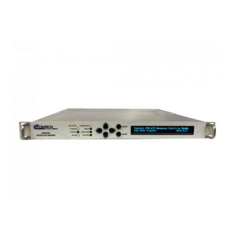
CDM-425 Advanced Satellite Modem
Revision 0
Table of Contents iv MN-CDM-425
6.2.1.8 CONFIG: CnC.............................................................................................................6–41
6.2.1.8.1 CONFIG: CnC Mode...........................................................................................6–41
6.2.1.8.2 CONFIG: CnC CONFIG: CnC Freq-Offset.....................................................6–42
6.2.1.8.3 CONFIG: CnC Search-Delay..............................................................................6–42
6.2.1.8.4 CONFIG: CnC PMSI-Control ..............................................................................6–43
6.2.1.9 CONFIG: EDMAC .......................................................................................................6–44
6.2.1.10 CONFIG: Misc.............................................................................................................6–45
6.2.1.10.1 CONFIG: Misc G.703-LineCode (Ternary Code).................................................6–45
6.2.1.10.2 CONFIG: Misc RTS.............................................................................................6–46
6.2.1.10.3 CONFIG: Misc Warm-Up.....................................................................................6–46
6.2.1.10.4 CONFIG: Misc Stats (Statistics) ..........................................................................6–47
6.2.1.10.5 CONFIG: Misc MEO (Medium Earth Orbit).........................................................6–47
6.2.1.11 CONFIG: Mask............................................................................................................6–48
6.2.1.11.1 CONFIG: Mask AIS.............................................................................................6–49
6.2.1.11.2 CONFIG: Mask Buffer/Ref ..................................................................................6–49
6.2.1.11.3 CONFIG: Mask RxIF...........................................................................................6–49
6.2.1.11.4 CONFIG: Mask TxClk..........................................................................................6–50
6.2.1.11.5 CONFIG: Mask CnC............................................................................................6–50
6.2.1.11.6 CONFIG: Mask Terr.............................................................................................6–50
6.2.1.11.7 CONFIG: Mask BUC...........................................................................................6–51
6.2.1.11.8 CONFIG: Mask LNB............................................................................................6–51
6.2.1.11.9 CONFIG: Mask ClkExt (G.703 Clock Extension Mask).......................................6–51
6.2.1.12 CONFIG: Remote (Remote Control)...........................................................................6–52
6.2.1.12.1 CONFIG: Remote Local or Serial Remote Settings............................................6–52
6.2.1.13 CONFIG: IP.................................................................................................................6–52
6.2.1.13.1 CONFIG: IP Addresses.......................................................................................6–53
6.2.1.13.2 CONFIG: IP SNMP..............................................................................................6–53
6.2.1.13.3 CONFIG: IP Setup...............................................................................................6–56
6.2.1.13.4 CONFIG: IP ANT (Advanced Network Timing)....................................................6–69
6.2.1.13.5 CONFIG: IP PortMonitor .....................................................................................6–72
6.2.1.13.6 CONFIG: IP AccessList........................................................................................6–72
6.2.1.13.7 CONFIG: IP PktP-Enable....................................................................................6–73
6.2.2 SELECT: Test Menu Branch ...................................................................................................6–74
6.2.2.1 SELECT: TEST Mode.............................................................................................6–74
6.2.2.2 SELECT: TEST BERT.............................................................................................6–77
6.2.2.2.1 SELECT: TEST BERT Config.........................................................................6–77
6.2.2.2.2 SELECT: TEST BERT Monitor........................................................................6–77
6.2.2.3 SELECT: TEST CnC-APC-Monitor.........................................................................6–78
6.2.2.4 SELECT: TEST Uncorrected-BER..........................................................................6–78
6.2.3 SELECT: Monitor Menu Branch..............................................................................................6–80
6.2.3.1 Monitor: Live-Alarms ...................................................................................................6–80
6.2.3.2 Monitor: Stored Events Stored Events: Clear-All: No (No, Yes).................................6–82
6.2.3.3 Monitor: ACM...............................................................................................................6–82
6.2.3.4 Monitor: Statistics........................................................................................................6–83
6.2.3.4.1 Monitor: Statistics Examples....................................................................................6–83
6.2.3.5 Monitor: Rx Parameters Rx-Parameters: EbNo=11.4dB ∆F=+011.7kHz...................6–85
6.2.3.6 Monitor: RemoteEbNo.................................................................................................6–86
6.2.3.7 Monitor: AUPC Parameters.........................................................................................6–86
6.2.3.8 Monitor: CnC-Parameters...........................................................................................6–87
6.2.3.9 Monitor: IP Statistics....................................................................................................6–87
6.2.4 SELECT: Info (Information) Menu Branch ..............................................................................6–88
6.2.4.1 Info: All.........................................................................................................................6–88
6.2.4.2Info: ID.........................................................................................................................6–88
6.2.4.3 Info: Mode ...................................................................................................................6–89
6.2.4.4 Info: Tx.........................................................................................................................6–89
6.2.4.5 Info: Rx........................................................................................................................6–90
