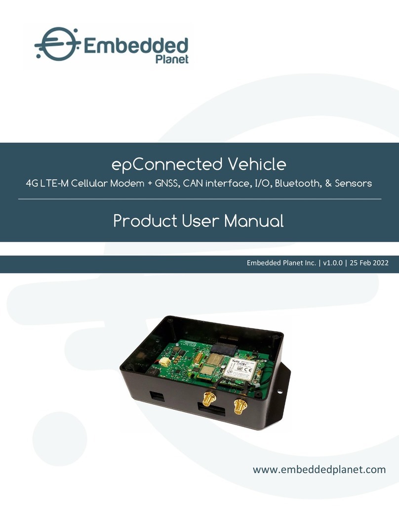
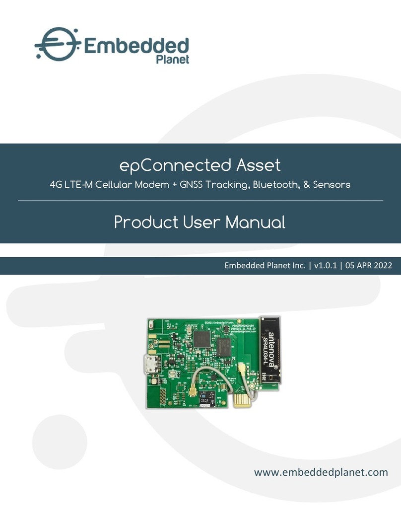
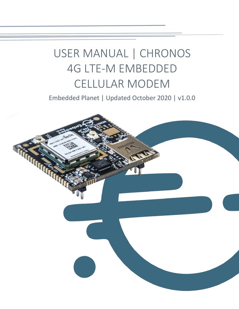
Embedded Planet Agora Operational manual

Agora
4G LTE Cellular Modem + MCU, GNSS, Bluetooth, LoRa, & Sensors
Product User Manual
www.embeddedplanet.com
Embedded Planet Inc. | v1.0.0 | 11 Feb 2022

Embedded Planet, Inc. Agora | Product User Manual Document Version: 1.0.0 | 11 Feb 22
Embedded Planet, Inc. | 31225 Bainbridge Rd Suite N, Solon, OH 44139 | 216-245-4180 | www.embeddedplanet.com | Page 1 of 47
About This Manual
The Agora User Manual provides detailed information encompassing the design, description, and
integration of the Agora device. For elaboration on drawings, software, or other specific product details there
may be other sources of information to which this document points as reference. For the latest documentation,
including document & certification updates, please always refer to the Embedded Planet documentation page:
https://www.embeddedplanet.com/product-documentation
Product Web Page
The Agora product page by Embedded Planet provides description & resources related to this product.
This page can be located at https://www.embeddedplanet.com/agora

Embedded Planet, Inc. Agora | Product User Manual Document Version: 1.0.0 | 11 Feb 22
Embedded Planet, Inc. | 31225 Bainbridge Rd Suite N, Solon, OH 44139 | 216-245-4180 | www.embeddedplanet.com | Page 2 of 47
Contents
1. Introduction ...................................................................................................................................................... 4
2. Orderable Part Numbers .................................................................................................................................. 5
3. Additional Resources ......................................................................................................................................... 6
4. Feature Callouts ................................................................................................................................................ 7
4.1. Feature Callouts | Wireless Modules .............................................................................................................. 7
4.2. Feature Callouts | Antennae ........................................................................................................................... 7
4.3. Feature Callouts | Connectors ....................................................................................................................... 8
4.4. Feature Callouts | Sensors ............................................................................................................................... 9
4.5. Feature Callouts | Mounting & Interaction ..................................................................................................... 10
5. Block Diagram ................................................................................................................................................... 11
6. Device Specifications ........................................................................................................................................ 12
7. Modules ............................................................................................................................................................. 13
7.1. Modules | Bluetooth + MCU .............................................................................................................................. 13
7.2. Modules | LoRaWAN ........................................................................................................................................ 14
7.3. Modules | Cellular + GNSS ............................................................................................................................... 14
8. Sensors .............................................................................................................................................................15
8.1. Sensors | Temp/Humidity/Pressure/Gas (U2) .................................................................................................. 16
8.2. Sensors | Temp/Humidity (U7) ......................................................................................................................... 16
8.3. Sensors | 6-Axis IMU (U9) .................................................................................................................................. 17
8.4. Sensors | 9-Axis IMU (U6) .................................................................................................................................. 17
8.5. Sensors | Time-of-Flight/ToF (U14) .................................................................................................................. 18
8.6. Sensors | Microphone (U5) .............................................................................................................................. 18
9. GPIO Elements ................................................................................................................................................... 19
9.1. GPIO Elements | Red LED .................................................................................................................................. 19
9.2. GPIO Elements | Pushbutton ............................................................................................................................ 19
10. Memory ............................................................................................................................................................. 19
11. Power ............................................................................................................................................................... 20
11.1. Power | Battery ................................................................................................................................................. 21
11.2. Power | Battery Charging ................................................................................................................................ 21
11.3. Power | Battery Monitor ................................................................................................................................... 21
11.4. Power | Sensor Power Control ........................................................................................................................ 22
11.5. Power | Cell Power Control ............................................................................................................................. 22
11.6. Power | Battery Life ........................................................................................................................................ 22
12. Development .................................................................................................................................................... 23
12.1. Development | Programming & Flidor Development Board .......................................................................... 23
12.2. Development | Programming & Debugging .................................................................................................. 23
12.3. Development | Software ................................................................................................................................ 25
12.4. Development | Hardware Integration .......................................................................................................... 26
13. Pinouts ............................................................................................................................................................. 27
13.1. MCU Pinout (BT840) .......................................................................................................................................... 27
13.2. Tectonic Edge™ Pinout ................................................................................................................................... 29
13.3. Modem Header Pinout .................................................................................................................................... 32
14. Antennae ......................................................................................................................................................... 33
14.1. Antennae | Cellular Antenna ......................................................................................................................... 34
14.2. Antennae | GNSS Antenna ............................................................................................................................. 36

Embedded Planet, Inc. Agora | Product User Manual Document Version: 1.0.0 | 11 Feb 22
Embedded Planet, Inc. | 31225 Bainbridge Rd Suite N, Solon, OH 44139 | 216-245-4180 | www.embeddedplanet.com | Page 3 of 47
14.3. Antennae | LoRa Antenna ............................................................................................................................. 37
15. Electrical Specifications ................................................................................................................................... 38
15.1. Absolute Maximum & Minimum Ratings........................................................................................................... 38
15.2. Recommended Operating Conditions ........................................................................................................... 38
16. Mechanical Specifications................................................................................................................................ 39
16.1. Configuration Form Factors ........................................................................................................................... 39
16.2. Physical Parameters ....................................................................................................................................... 40
16.3. Mechanical Drawings ...................................................................................................................................... 40
16.3.1. Mechanical Drawings | Assembly Views ..................................................................................................... 41
16.3.2. Mechanical Drawings | Dimensions (Top) .................................................................................................. 42
16.4. Environmental Specifications ........................................................................................................................ 43
17. Regulatory Information ................................................................................................................................... 43
17.1. Cellular Certifications & Endorsements ........................................................................................................ 43
17.2. RoHS Compliance ........................................................................................................................................... 44
17.3. Interferance Statement ................................................................................................................................ 44
17.4. FCC and ISED Compliance ............................................................................................................................. 44
17.4.1. FCC and ISED Compliance | FCC Certificate .............................................................................................. 44
17.4.2. FCC and ISED Compliance | ISED Certificate .............................................................................................. 45
17.5. Wireless Notice ............................................................................................................................................... 45
17.6. Antenna Notice: FCC & ISED ........................................................................................................................... 45
17.7. End-Product Labeling Requirements ............................................................................................................. 46
17.8. FCC Additional Testing, Part 15 Subpart B Disclaimer .................................................................................... 46
18. Revision History ................................................................................................................................................ 47
Table 1 – Part Number Configurator ....................................................................................................................................... 5
Table 2 – Part Number Options .............................................................................................................................................. 6
Table 3 – Wireless modules .................................................................................................................................................... 7
Table 4 - Antennae .................................................................................................................................................................. 7
Table 5 – Connectors .............................................................................................................................................................. 8
Table 6 – Sensors .................................................................................................................................................................... 9
Table 7 – Mounting & Interaction ......................................................................................................................................... 10
Table 8 – Device specifications ............................................................................................................................................. 12
Table 9 – Device specifications ............................................................................................................................................. 15
Table 10 – MCU Pinout (BT840) ............................................................................................................................................ 27
Table 11 – Tectonic Edge Pinout (Top) ................................................................................................................................. 30
Table 12 – Tectonic Edge Pinout (Bottom) ........................................................................................................................... 31
Table 13 – MFX3.07.0150C electrical specifications ............................................................................................................. 35
Table 14 – absolute maximum & minimums ........................................................................................................................ 38
Table 15 – recommended operating conditions ................................................................................................................... 38
Table 16 – physical parameters ............................................................................................................................................ 40
Table 17 – environmental specifications .............................................................................................................................. 43
Table 18 – FCC & ISED max gain by band .............................................................................................................................. 45
Table 19 – revision history .................................................................................................................................................... 47

Embedded Planet, Inc. Agora | Product User Manual Document Version: 1.0.0 | 11 Feb 22
Embedded Planet, Inc. | 31225 Bainbridge Rd Suite N, Solon, OH 44139 | 216-245-4180 | www.embeddedplanet.com | Page 4 of 47
1. Introduction
The Agora wireless platform is a multi-sensor modem assembly with integrated MCU designed to be used as a
versatile solution for the rapid integration of Cellular, Bluetooth, and/or LoRa connectivity to all kinds of new or
existing product designs. It is capable of hosting a variety of environmental sensors and communicating sensor data
wirelessly over 2.4GHz Bluetooth, 868/915MHz LoRa or 4G LTE Cat1 depending on configuration. Leveraging Agora
helps cut design time, complexity, and R&D effort, getting end-user products to market faster. Sensor options can
accommodate the monitoring of temperature, relative humidity, barometric pressure, VOC gas, air quality, audio,
distance (Time of Flight / ToF), and inertial forces (accelerometer/gyroscope/magnetometer). Agora can be available
as a PCBA (printed circuit board assembly) or as a full module which includes a custom-designed plastic enclosure,
LiPo battery, and LiPo charging circuit with a micro-USB input. The Agora board itself can be integrated into your
own system using either a standard twin 10-pin header modem footprint or its specialized Tectonic Edge™ board-
edge connector. Choose whether to power it from a dedicated LiPo battery, ac/dc wall-wart, or your own hardware.
Certifications include PTCRB, Verizon, AT&T TRENDI, and ARM MBED Enabled.

Embedded Planet, Inc. Agora | Product User Manual Document Version: 1.0.0 | 11 Feb 22
Embedded Planet, Inc. | 31225 Bainbridge Rd Suite N, Solon, OH 44139 | 216-245-4180 | www.embeddedplanet.com | Page 5 of 47
2. Orderable Part Numbers
Table 1 and Table 2 demonstrate the flexibility of possible device configurations. Availability of specific
configurations depend on current stocking & ordering conditions. The Embedded Planet shop is hosted at
shop.embeddedplanet.com. Please contact Embedded Planet sales to ask about a configuration not found in the
Embedded Planet shop: sales@embeddedplanet.com.
TABLE 1 – PART NUMBER CONFIGURATOR
Design/Long Part Number: 263B 9
NA 4 G B 6 N S I R P H J N
An example configuration for Agora would be 263B-9EWW4GB9NSIRPNJS which, according to the following
Table 2, would include the following:
1. 915MHz LoRa module with antenna
2. 4G LTE Cat M1 “Worldwide” module
3. 4FF/”nano” SIM card connector
4. GNSS hardware
5. BME680 temp/humidity sensor
6. 9-axis IMU
7. Time-of-Flight sensor
8. Microphone
9. Red LED
10. Pushbutton
11. Battery connector
12. Slide-style on/off switch
Design = 263B
1 LoRa module
2 Cellular module
3 SIM
4 GNSS
5 Environmental Sensor
6 Inertial Sensor
7 Reserved
8 Time of Flight Sensor
9 Microphone
10 LED Indicator
11 Pushbutton input
12 Modem headers
13 Battery connector
14 Switch

Embedded Planet, Inc. Agora | Product User Manual Document Version: 1.0.0 | 11 Feb 22
Embedded Planet, Inc. | 31225 Bainbridge Rd Suite N, Solon, OH 44139 | 216-245-4180 | www.embeddedplanet.com | Page 6 of 47
Table 2 – Part Number Options
Option
Designator
Description
1
LoRa
N No LoRa
9 915MHz LoRa module
9E 915MHz LoRa module, external antenna
8 868MHz LoRa module
2
Cellular
N No cell
NA 4G LTE Cat M1 AT&T / Verizon module
WW 4G LTE Cat M1 “Worldwide” module
3
SIM
N No SIM
4 4FF (Nano) SIM (to match cell)
E Reserved
4
GNSS
(Requires Option 2)
N No GNSS
G GNSS hardware
5
Environment
N No environmental sensor
B Bosch BME680: temp, humidity, pressure, gas
S SiLabs Si7021-A20: temp, humidity
6
Inertia
N No inertial sensor
6 InvenSense ICM-20602: 3-axis accel, 3-axis gyro
9 ST LSM9DS1: 3-axis accel, 3-axis gyro, 3-axis mag
7
Reserved
N
8
Time of Flight
N No time of flight sensor
S ST VL53L0X
9
Microphone
N No microphone
I InvenSense ICS-43432
10
LED Indicator
N No LED indicator
R Red LED
B Blue LED
11
Pushbutton
N No pushbutton
P Pushbutton
12
Modem headers
N No modem headers
H Modem headers
13
Battery Connector
N No battery connector (powered through Tectonic Edge™)
J JST battery connector
14
On/Off Switch
S or Blank ON/OFF switch populated
C No switch (powered through Tectonic Edge™)
3. Additional Resources
Agora page:
https://www.embeddedplanet.com/agora
Additional Documentation (including Quick Start materials):
https://www.embeddedplanet.com/product-documentation
Flidor Programmer & Debugger:
https://www.embeddedplanet.com/flidor
Telit ME910 cellular & GNSS module:
https://www.telit.com/product-series/me910/

Embedded Planet, Inc. Agora | Product User Manual Document Version: 1.0.0 | 11 Feb 22
Embedded Planet, Inc. | 31225 Bainbridge Rd Suite N, Solon, OH 44139 | 216-245-4180 | www.embeddedplanet.com | Page 7 of 47
4. Feature Callouts
4.1. Feature Callouts | Wireless Modules
TABLE 3 – WIRELESS MODULES
Category Reference Functionality Description / Purpose
Wireless Module U11 LoRaWAN transceiver LoRaWAN module (915MHz or 868MHz)
Wireless Module U3 Bluetooth transceiver nRF52840 BLE + MCU module
Wireless Module U12 Cellular transceiver Telit ME910 cellular + GNSS module
4.2. Feature Callouts | Antennae
TABLE 4 - ANTENNAE
Category Reference Functionality Description / Purpose
Antenna ANT1 LoRaWAN antenna Onboard antenna. See Antenna section for more.
Antenna U3 Bluetooth antenna Onboard, no offboard connections
Antenna n/a GNSS antenna Adhesive-backed, mounting optional
Connector J8 GNSS U.FL connector Offboard antenna supported
Connector J7 Cellular U.FL connector Offboard antenna supported
Connector J5 LoRa U.FL connector Offboard antenna supported
U11:
LoRa
module
U
3
:
Bluetooth
module (+MCU)
U
12:
Cellular
module
ANT
1: Onboard
LoRaWAN antenna
U3
: Onboard
BLE antenna
J7
:
Cellular
U.FL connector
J8:
GNSS U.FL
connector
1: Onboard
GNSS
antenna
J5:
LoRa U.FL
connector

Embedded Planet, Inc. Agora | Product User Manual Document Version: 1.0.0 | 11 Feb 22
Embedded Planet, Inc. | 31225 Bainbridge Rd Suite N, Solon, OH 44139 | 216-245-4180 | www.embeddedplanet.com | Page 8 of 47
4.3. Feature Callouts | Connectors
TABLE 5 – CONNECTORS
Category Reference
Functionality Description / Purpose
Board Interface TE1 Board edge/finger Tectonic Edge™ programming & debug
Connector BT1 Battery tab connector Optional battery tab connection
Connector J1 SIM card connector SIM card interface (eSIM option also available)
Connector J2, J4 Socket modem pin headers Drop-in 20-pin header modem applications
Connector J6 JST battery connector Optional JST battery connection (LiPo)
J2,
J4:
Socke
t
modem twin pin
header array
TE1:
Tectonic
Edge™ board edge
BT1:
Battery
tab
connector
J1:
SIM card
connector
J6:
JST battery
connector

Embedded Planet, Inc. Agora | Product User Manual Document Version: 1.0.0 | 11 Feb 22
Embedded Planet, Inc. | 31225 Bainbridge Rd Suite N, Solon, OH 44139 | 216-245-4180 | www.embeddedplanet.com | Page 9 of 47
4.4. Feature Callouts | Sensors
TABLE 6 – SENSORS
Category Reference Functionality Description / Purpose
Sensor U5 Microphone ICS-43432 | Sound sensor
Sensor U7 Temperature/Humidity Si7021-A20 | Environmental sensor
Sensor U2 Temperature/Humidity/Pressure/Air Quality BME680 | Environmental sensor
Sensor U9 Accelerometer/Gyroscope ICM-20602 | Inertial sensor
Sensor U6 Accelerometer/Gyroscope/Magnetometer LSM9DS1 | Inertial sensor
Sensor U14 Time-of-Flight (ToF) VL53L0X | Distance sensor
U9:
Accelerometer/Gyro
U6:
Accelerometer/Gyro
/magnetometer
U14:
Time
-
of
-
Flight
U5:
Microphone
U7:
Temperature/Humidity
U2:
Temp/humidity/
pressure/air quality

Embedded Planet, Inc. Agora | Product User Manual Document Version: 1.0.0 | 11 Feb 22
Embedded Planet, Inc. | 31225 Bainbridge Rd Suite N, Solon, OH 44139 | 216-245-4180 | www.embeddedplanet.com | Page 10 of 47
4.5. Feature Callouts | Mounting & Interaction
TABLE 7 – MOUNTING & INTERACTION
Category Reference Functionality Description / Purpose
Mounting MB1-4 Mounting bracket For use with the Agora plastic housing
Mounting MH1-4 Mounting hole For mounting the Agora
Pushbutton SW1 Pushbutton for GPIO usage User programmable functionality
Switch SW2 ON/OFF switch to the board Power switch to the Agora
Label LB1 Board ID Label Identification & serialization reference
MH1
-
3:
Board
mounting holes
SW1:
GPIO
P
ushbutton
LB1:
Serial
Number / Board
ID Label
MB1
-
4:
Board
mounting
brackets
SW2:
ON/OFF
switch

Embedded Planet, Inc. Agora | Product User Manual Document Version: 1.0.0 | 11 Feb 22
Embedded Planet, Inc. | 31225 Bainbridge Rd Suite N, Solon, OH 44139 | 216-245-4180 | www.embeddedplanet.com | Page 11 of 47
5. Block Diagram

Embedded Planet, Inc. Agora | Product User Manual Document Version: 1.0.0 | 11 Feb 22
Embedded Planet, Inc. | 31225 Bainbridge Rd Suite N, Solon, OH 44139 | 216-245-4180 | www.embeddedplanet.com | Page 12 of 47
6. Device Specifications
TABLE 8 – DEVICE SPECIFICATIONS
Feature/Specification Description
Cellular Capabilities
Cellular Technologies: LTE-M (LTE CAT M1), SMS
Lower power modes: PSM, eDRX
Operating Frequencies: 699MHz to 1980MHz
Cellular Operating Mode: Half-duplex FDD
RF Output Power: Up to +23 ±2 dBm (Power Class 3)
Internet Protocols IPv4/IPv6 stack with TCP and UDP protocols
TLS/DTLS
LTE CAT M1 Specification
Bands (WW): B1(2100), B2(1900), B3(1800), B4(AWS1700), B5(850), B8(900), B12(700),
13(700), B18(800), B19(800), B20(800), B26(850), B28(700)
Bands (NA): B2(1900), B4(AWS1700), B12(700) B13(700)
Uplink: up to 375 kbps
Downlink: up to 300 kbps
SIM
Removable: 4FF (nano) SIM card slot
Board-mounted: MFF2
Internal: Telit simWISE™
Cellular Certifications
PTCRB: Complete
AT&T: Complete
Verizon: Complete
GNSS Specifications
Constellations: GPS, GLONASS, BeiDou, Galileo, QZSS
Tracking Sensitivity: -161dBm
Navigation Sensitivity: -158dBm
Cold Start Sensitivity: -146dBm
Input Voltage
Nominal Voltage: 3.7 VDC
Voltage Range: 1.7-5 VDC
LiPo Specification: 3.2-4.2 VDC
Dimensions
Board
-
only, f
ully
populated
:
70 mm
x
45 mm
x
16.3
mm
(
2.75
in
x 1.
77
in x 0.
64
in)
Plastic housing assembly: 102.3 mm x 59.3 mm x 43 mm (4.03 in x 2.33 in x 1.69 in)
Environmental
Operating Temperature
Range
(PCBA
on
ly)
:
-
4
0°C to +85°C
Storage Temperature Range (PCBA only): -40°C to +85°C
Operating Temperature Range (with battery): -20°C to +60°C
Storage Temperature Range (with battery): -20°C to +60°C
Humidity Range: 20% RH to 90% RH

Embedded Planet, Inc. Agora | Product User Manual Document Version: 1.0.0 | 11 Feb 22
Embedded Planet, Inc. | 31225 Bainbridge Rd Suite N, Solon, OH 44139 | 216-245-4180 | www.embeddedplanet.com | Page 13 of 47
7. Modules
7.1. Modules | Bluetooth + MCU
The MCU on the Agora is Nordic’s nRF52840 which is incorporated into the Fanstel BT840 module (U3). The
BT840 contains the nRF52840 along with its supporting hardware and an integrated Bluetooth PCB antenna.
Features of the Fanstel BT840 include the nRF52840 SoC, ARM® Cortex®-M4 32-bit processor with FPU 64MHz,
128-bit AES/ECB/CCM/AAR co-processor, ARM® TrustZone® Cryptocell 310 security subsystem, Bluetooth 5
IEEE 802.15.1-2006 2.4GHz transceiver, integrated PCB trace antenna, 1MB on-chip flash, 256kB on-chip RAM,
USB 2.0 full speed (12Mbps) controller, QPSI 32MHz interface, and 12-bit 200ksps ADC (up to 8 channels).
Agora supports the development of the nRF52840 MCU via the Tectonic Edge™ board edge connection
system used throughout Embedded Planet products. Flidor, a programming & debug host board with Tectonic
Edge™ compatibility, is the choice development tool for use with Agora. Flidor supports drag-and-drop
programming along with streamlined debug features that make it the go-to method for programming Agora.
Some configurations of Agora assemblies, such as the Agora Development Kit available in the Embedded Planet
online shop, include a Flidor for development. The Agora Development Kit is strongly recommended for users
who want to development on Agora.
More on Flidor can be found at https://www.embeddedplanet.com/product-documentation/#flidor
Further details on the Nordic nRF52840 can be found here:
https://www.nordicsemi.com/Products/Low-power-short-range-wireless/nRF52840
Further details on the Fanstel BT840 module can be found here:
https://www.fanstel.com/bt840
U
3
:
Fanstel BT840
module containing an
nRF52840 (MCU+BLE)
module

Embedded Planet, Inc. Agora | Product User Manual Document Version: 1.0.0 | 11 Feb 22
Embedded Planet, Inc. | 31225 Bainbridge Rd Suite N, Solon, OH 44139 | 216-245-4180 | www.embeddedplanet.com | Page 14 of 47
7.2. Modules | LoRaWAN
LoRaWAN is supported on Agora by the NiceRF LoRa1276-C1-915 module. This module contains a
Semtech SX1276 transceiver. This module is available in either 868MHz or 915MHz center frequency
configuration; the default used for Agora is 915MHz. Using this module along with the NiceRF SW915-TH12
antenna maintains the certifications that come with the NiceRF module. Specifications for this antenna include
the following:
Frequency range: 915MHz ±5MHz
VSWR: ≤ 1.5
Input impedance: 50ohms
Maximum input power: 5W
Gain: 2.15dBi
For more information on the NiceRF LoRa1276-C1-915 (915MHz) module, please see:
https://www.nicerf.com/products/detail/lora-wireless-transceiver-module-lora1276-c1-915.html
For more information on the NiceRF LoRa1276-C1-868 (868MHz) module, please see:
https://www.nicerf.com/products/detail/lora-wireless-transceiver-module-lora1276-c1-868.html
7.3. Modules | Cellular + GNSS
The Agora device leverages the Telit ME910C1 family of modules for cellular connectivity and GNSS
functionality. The ME910 modules supported by Agora are the ME910C1-NA and the ME910C1-WW.
ME910C1-NA
o Cat M1: bands B2, B4, B12, B13
o North America, AT&T, and Verizon
ME910C1-WW
o Cat M1, NB-IoT: bands B1, B2, B3, B4, B5, B8, B12, B13, B18, B19, B20, B26, B28
o 2G fallback: bands B2, B3, B5, B8
o Worldwide coverage
More information on the Telit ME910 series modules can be found at:
https://www.telit.com/me910c1/
U11:
LoRa
module

Embedded Planet, Inc. Agora | Product User Manual Document Version: 1.0.0 | 11 Feb 22
Embedded Planet, Inc. | 31225 Bainbridge Rd Suite N, Solon, OH 44139 | 216-245-4180 | www.embeddedplanet.com | Page 15 of 47
A U.FL connector is provided for use with external cellular antennae, along with additional U.FL connector
provided for connection to an external GNSS antenna. The GNSS antenna connection supports active GNSS
antenna usage.
The recommended cellular antenna is Taoglas MFX3.07.0150C. This antenna has the following specifications:
698MHz to 3GHz
>45% efficiency on all bands
Input impedance: 50ohms
Maximum input power: 5W
5dBi peak gain
More on the Taoglas MFX3.07.0150C can be found at:
https://www.taoglas.com/product/mfx3-07-cat-m1-wideband-flexible-antenna-150mm-o1-37mm-coax-cable/
https://www.taoglas.com/datasheets/MFX3.07.0150C.pdf
8. Sensors
Agora supports up to 9 different sensor data type parameters across 4 different sensor categories and 6 sensor
selection options. Table 9 describes the different sensor options available. See section 4.4 Feature Callouts |
Sensors of this manual for reference of where each sensor is located on the Agora board.
TABLE 9 – DEVICE SPECIFICATIONS
C
ategory
Module
Capabilities
Ref
Environ
ment
al
Bosch BME680
Temperature, humidity,
barometric pressure,
VOC
gas
U2
Environ
ment
al
SiLabs Si7021
-
A20
Temperature, humidity
U7
Inertial
Inven
Sense
ICM-20602
6
-
a
xis IMU:
3
-
a
xis
a
ccelerom
eter
, 3
-
a
xis gyroscope
U7
Inertial
ST LSM
9DS1
9
-
a
xis IMU: 3
-
a
xis acceler
om
eter, 3
-
a
xis gyroscope,
3
-
axis magnetometer
U
6
Distance
ST VL53L0X
Range
measurement
(Time
-
of
-
Flight)
(ToF)
U14
Sound
Inven
Sense ICS
-
43432
Mi
cr
ophon
e
U5

Embedded Planet, Inc. Agora | Product User Manual Document Version: 1.0.0 | 11 Feb 22
Embedded Planet, Inc. | 31225 Bainbridge Rd Suite N, Solon, OH 44139 | 216-245-4180 | www.embeddedplanet.com | Page 16 of 47
8.1. Sensors | Temp/Humidity/Pressure/Gas (U2)
The Agora design supports the Bosch BME680 environmental sensor. This sensor has the ability to
measure data regarding temperature, humidity, barometric pressure, and VOC gas. Features of this sensor
include:
Temperature sensor: ±1°C temperature accuracy (0°C to +65°C), up to 20-bit resolution
Humidity sensor: ±3% relative humidity accuracy (20-80% RH), 16-bit resolution
Pressure sensor: ±0.6hPa pressure accuracy (300-1000hPa), up to 20-bit resolution
VOC gas sensor:
o Ethane: 5% accuracy
o Isoprene / 2-methyl-1,3 Butadiene: 5% accuracy
o Ethanol: 5% accuracy
o Acetone: 5% accuracy
o Carbon Monoxide: 2% accuracy
This sensor communicates with the nRF52840 MCU over I2C using the address 1110110b (0x76).
For more information on the Bosch BME680 please see:
https://www.bosch-sensortec.com/products/environmental-sensors/gas-sensors/bme680/
8.2. Sensors | Temp/Humidity (U7)
The Agora design supports the Silicon Labs Si7021-A20 temperature & humidity sensor. Features of this
sensor include:
Integrated ADC: up to 14-bit for temperature and up to 12-bit for humidity
±0.4°C temperature accuracy (-10°C to +85°C)
±3% relative humidity accuracy (0-80% RH)
This sensor communicates with the nRF52840 MCU over I2C using the address 1000000b (056x40).
For more information on the Silicon Labs Si7021-A20, please see:
https://www.silabs.com/sensors/humidity/si7006-13-20-21-34/device.si7021-a20-gm

Embedded Planet, Inc. Agora | Product User Manual Document Version: 1.0.0 | 11 Feb 22
Embedded Planet, Inc. | 31225 Bainbridge Rd Suite N, Solon, OH 44139 | 216-245-4180 | www.embeddedplanet.com | Page 17 of 47
8.3. Sensors | 6-Axis IMU (U9)
The Agora design supports the InvenSense ICM-20602 6-axis IMU sensor. This sensor is comprised of an
accelerometer and a gyroscope. Features of this sensor include:
Integrated 16-bit ADC
3-axis gyroscope
Programmable ranges of ±250dps, ±500dps, ±1000dps and ±2000dps
Sensitivity error: ±1%
Noise: ±4mdps/√Hz
3-axis accelerometer
Programmable ranges of ±2g, ±4g, ±8g, ±16g
Sensitivity error ±1%
Noise: 100µg/√Hz
This sensor communicates with the nRF52840 MCU over I2C using the address (1101000b, 0x68).
For more information on the InvenSense ICM-20602, please see:
https://invensense.tdk.com/products/motion-tracking/6-axis/icm-20602/
8.4. Sensors | 9-Axis IMU (U6)
The Agora design supports the ST LSM9DS1 9-axis IMU sensor. This sensor is comprised of an accelerometer,
a gyroscope, and a magnetometer. Features of this sensor include:
Integrated 16-bit ADC
3-axis gyroscope
Programmable ranges of ±245dps, ±500dps and ±2000dps
3-axis accelerometer
Programmable ranges of ±2g, ±4g, ±8g, ±16g
3-axis magnetometer
Programmable ranges of ±2gauss, ±4gauss, ±8gauss, ±16gauss
This sensor communicates with the nRF52840 MCU over I2C using the address (1101010b, 0x6A) for the
accelerometer/gyroscope, and 0011100b, 0x1C for the magnetometer.
For more information on the ST LSM9DS1, please see:
https://www.st.com/en/mems-and-sensors/lsm9ds1.html

Embedded Planet, Inc. Agora | Product User Manual Document Version: 1.0.0 | 11 Feb 22
Embedded Planet, Inc. | 31225 Bainbridge Rd Suite N, Solon, OH 44139 | 216-245-4180 | www.embeddedplanet.com | Page 18 of 47
8.5. Sensors | Time-of-Flight/ToF (U14)
The Agora design supports the ST VL53L0X time of flight (ToF) sensor. Features of this sensor include:
Distances measurement up to 2 meters
Ability to provide distance measurements despite target reflectance
White target max range: minimum 120cm indoor (4% accuracy), 60cm outdoor overcast (7% accuracy)
Grey target max range: minimum 70cm indoor (7% accuracy), 40cm outdoor overcast (12% accuracy)
SPAD array (Single Photon Avalanche Diodes) with embedded FlightSense technology
Laser invisible to the human eye
This sensor communicates with the nRF52840 MCU over I2C using the address 0101001b (0x29).
For more information on the ST VL53L0X, please see:
https://www.st.com/en/imaging-and-photonics-solutions/vl53l0x.html
8.6. Sensors | Microphone (U5)
The Agora design supports the InvenSense ICS-43432 microphone module. Features of this sensor include:
-26dB sensitivity
65dBA SNR
50Hz to 20kHz frequency response range
24-bit I2S interface
Low current consumption
This sensor communicates with the nRF52840 MCU over I2S using pins B1 (P25: SD), B4 (P06: SCK), and B5 (P08:
WS).
For more information on the InvenSense ICS-43432, please see:
https://invensense.tdk.com/products/digital/ics-43432/

Embedded Planet, Inc. Agora | Product User Manual Document Version: 1.0.0 | 11 Feb 22
Embedded Planet, Inc. | 31225 Bainbridge Rd Suite N, Solon, OH 44139 | 216-245-4180 | www.embeddedplanet.com | Page 19 of 47
9. GPIO Elements
A pushbutton and an LED are included as options on Agora. Both of these components are application-
controlled; they can be programmed to function in whatever way the application calls for. These features can
be used for development and/or in end-product applications.
9.1. GPIO Elements | Red LED
Agora features an onboard red LED controlled by programmable a GPIO pin on the nRF52840 MCU. This LED is
useful for development & debugging as well as for some end-product applications. The LED consumes a nominal
current of 4.4mA. The control signal for the LED is active-low and is connected to pin A4 (P05) of the nRF52840.
9.2. GPIO Elements | Pushbutton
Agora features an onboard pushbutton connected to a GPIO pin on the nRF52840 MCU. This pushbutton is
useful for development & debugging as well as for some end-product applications. This pushbutton signal is active-
low. The pushbutton GPIO pin is pulled high to 3.3V through an external 1M ohm resistor. When pressed, the
pushbutton connects the GPIO pin to COM (0V). The pushbutton GPIO pin is A2 (P29) of the nRF52840.
10. Memory
Agora supports onboard NOR flash packages controlled by the nRF52840 module. The flash module used in the
default Agora configuration is the 32Mb QSPI NOR flash W25Q32JVZPIQ by Winbond. This flash module includes the
following features:
Supports JEDEC standard manufacturer and device ID and SFDP
128-bit unique serial number
Four 256-byte Dedicated Security Area with OTP user-lockable bits
This flash module communicates with the nRF52840 MCU over QSPI lines using pins E1 (P20: IO0), E2 (P21: IO1),
C2 (P22: IO2), D1 (P23: IO3), D2 (P19: CLK), and C3 (P17: CS#).
For more information on the Winbond W25Q32JV series, please see:
https://www.winbond.com/hq/product/code-storage-flash-memory/serial-nor-flash/?__locale=en&partNo=W25Q32JV
Red GPIO LED
GPIO pushbutton
Table of contents
Other Embedded Planet Modem manuals
