Embention Veronte PCS User manual

Veronte PCS
Embention
Apr 21, 2022


CONTENTS
1 Technical 1
1.1 Features .................................................. 1
1.2 Mechanical Specifications ........................................ 1
1.3 Electrical Specifications ......................................... 2
1.4 Dimensions ................................................ 2
1.5 Versions ................................................. 5
1.6 Interfaces ................................................. 6
1.7 Part list .................................................. 9
2 Installation 11
2.1 ATTENTION .............................................. 11
2.2 Basic Connection Diagram ........................................ 12
2.3 Pinout ................................................... 12
2.4 Mechanical installation .......................................... 15
3 Operation 21
3.1 ON/OFF ................................................. 21
3.2 Battery Charge .............................................. 21
3.3 How to operate .............................................. 22
3.3.1 Computer Connection ...................................... 22
3.3.2 Joystick Connection ....................................... 23
3.3.3 Tracking Antenna Connection ................................. 24
3.3.4 Ethernet Internal Device Connection .............................. 24
3.3.5 Troubleshooting ......................................... 24
3.4 Advanced Wi-Fi Configuration ..................................... 26
4 Maintenance 27
4.1 Preventive Maintenance ......................................... 27
4.2 Corrective Maintenance ......................................... 27
4.3 Contact data ............................................... 30
i

ii
CHAPTER
ONE
TECHNICAL
1.1 Features
•Ready for operation
•Compatible with Veronte MCS or third party computers
•RTK & differential barometer base
•Wifi, Ethernet and USB communications
•Expansion bay (free space for customer electronics installations)
•Easy maintenance
•2 hours of battery life
•Battery over discharge protection
1.2 Mechanical Specifications
PCS Weight 5.9Kg max (depending on version)
PCS + Pole Weight 20.4Kg max (depending on version)
Operating temperature -20 to 60°C
Environmental
proteciton
IP54
Transport case Rugged plastic case, quad track wheels, pressure purge valve, side handles and carry
handle
1

Veronte PCS
1.3 Electrical Specifications
PCS DC input 14 to 24 VDC
PCS power 30W to 80W (depending on version)
Power supply AC
input
180-264 VAC 50-60 Hz
Battery type LiFePO4
Battery capacity 10 Ah
Battery operation
time
2 hours typically (depending on version)
Wifi 2.4GHz and 5GHz configurable Wifi output
RF1 and RF2
Frequencies
400MHz, 900MHz or 2.4GHz (depending on version)
RF1 and RF2
Impedance
50 Ohm
GNSS 1 Integrated GNSS antenna. 40dB Gain, covering GPS/QZSS L1, GLONASS G1, Galileo
E1, BeiDou B1, as well as SBAS
GNSS 2 SMA female connector for secondary GNSS antenna
Expansion bay I/O RS232, CAN and Ethernet
External I/O 1x USB, 2x CAN ports, Ethernet, 16x PWM, PPM, 4x ADCs and 1x I2C
Expansion bay power
outputs
3.3V/5A, 5V/5A, 12V/5A and 24V/5A
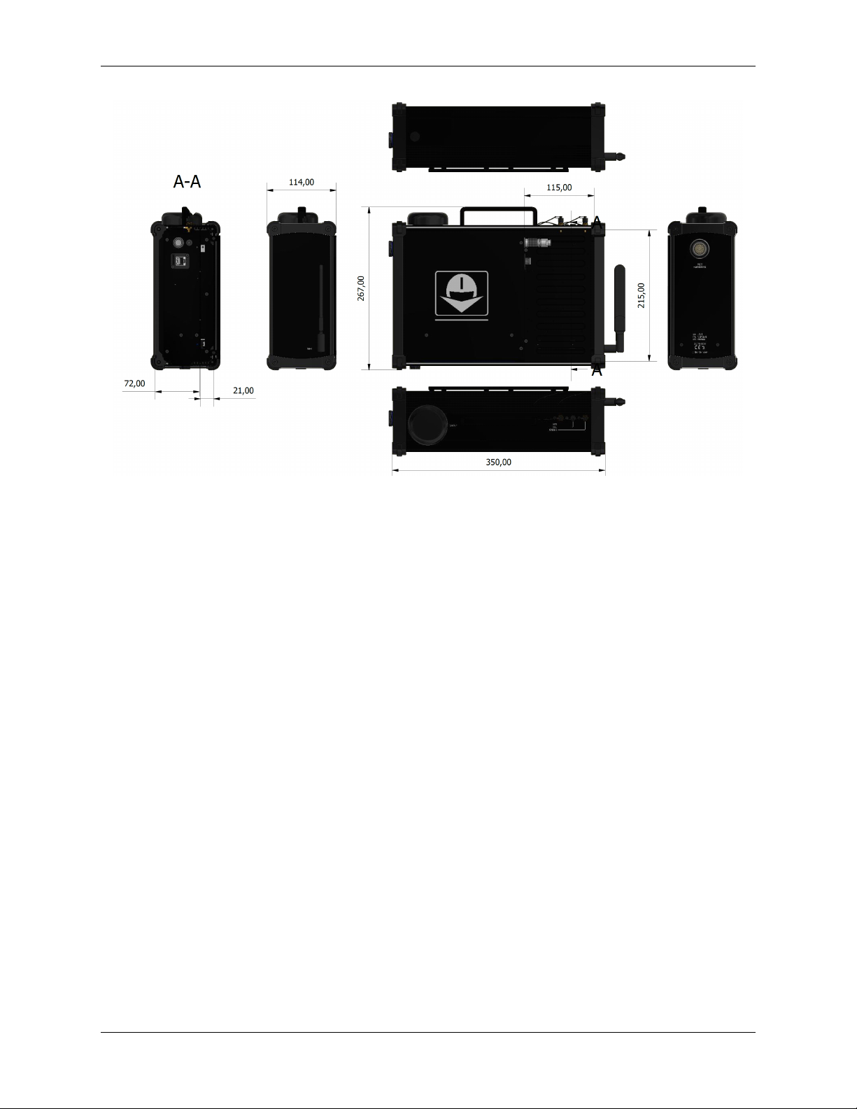
1.4 Dimensions
Below you can find a measurements drawing for the PCS.
2 Chapter 1. Technical
Veronte PCS
Fig. 1: Product Components - Interface dimensions
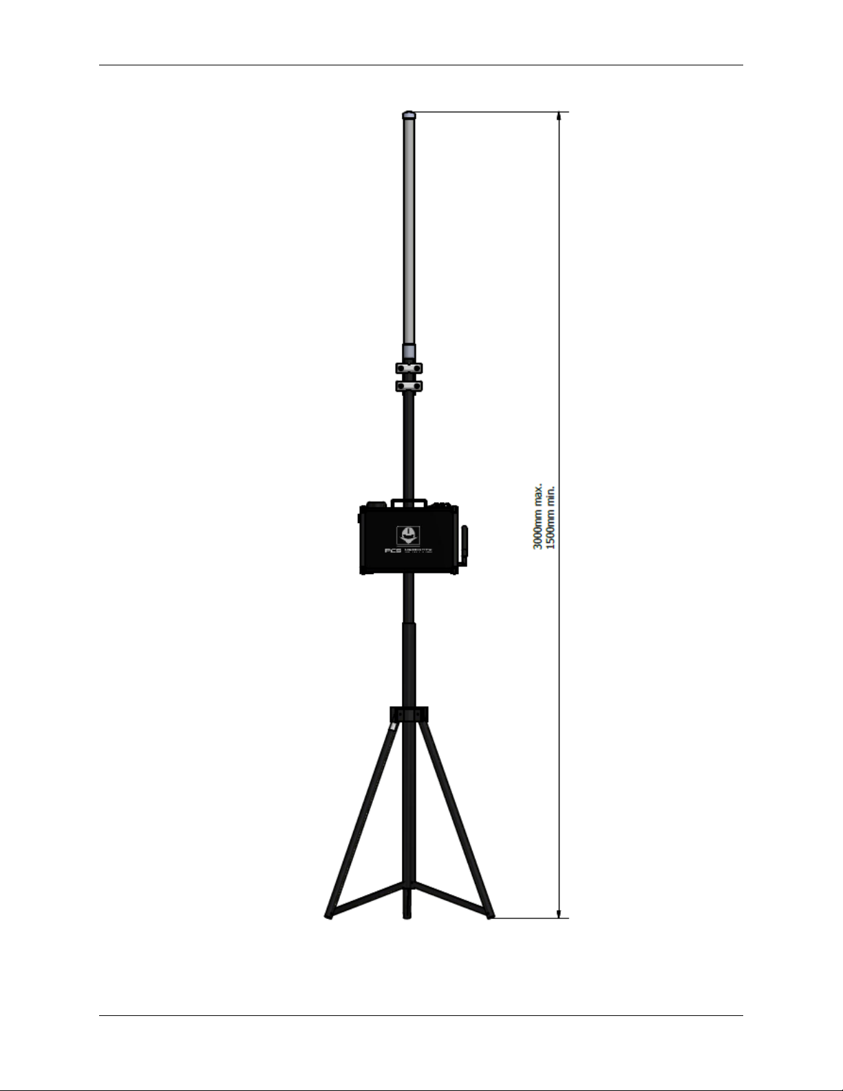
Veronte PCS is supplied together with a telescopic foldable mast that can be extended up to 3m. Next you can find the
maximum and the minimum dimensions of the system when installed.
1.4. Dimensions 3
Veronte PCS
Fig. 2: System Dimensions
4 Chapter 1. Technical

Veronte PCS
The whole system is delivered with a rugged plastic storage case for easy transportation.
Fig. 3: Rugged plastic case
1.5 Versions
This system is available with different device configurations in order to fit all operational requirements from each
application.
Versions with main specifications are described below.
Variant name FrequencyAmplifierRF
Power
Frequency
hopping
Video Antenna
type
Veronte PCS Control Station (w/o Datalink) V2.0 No
Radio
No No
Radio
No Radio No
Radio
No
antenna
Veronte PCS Control Station (Datalink DT 2.4GHz
- 5W - Video & TM/TC) V2.0
2.4GHz Yes 5W Yes Yes 15dBi
Veronte PCS Control Station (Datalink MH
2.4GHz - 10W - TM/TC) V2.0
2.4GHz Yes 10W Yes No 15dBi
Veronte PCS Control Station (Datalink MH
2.4GHz - 10W - Video & TM/TC) V2.0
2.4GHz Yes 10W Yes Yes 15dBi
Veronte PCS Control Station (Datalink MH
2.4GHz MIC - 0.1W - TM/TC) V2.0
2.4GHz No 100mW Yes No 15dBi
Veronte PCS Control Station (Datalink MH
900MHz - 10W - TM/TC) V2.0
900MHz Yes 10W Yes No 6dBi
Veronte PCS Control Station (Datalink MH
900MHz - 10W - Video & TM/TC) V2.0
900MHz Yes 10W Yes Yes 6dBi
Veronte PCS Control Station (Datalink MH
400MHz & 900MHz - 1W - TM/TC) V2.0
400MHz No 1W Yes No 2.15dBi
1.5. Versions 5
Veronte PCS
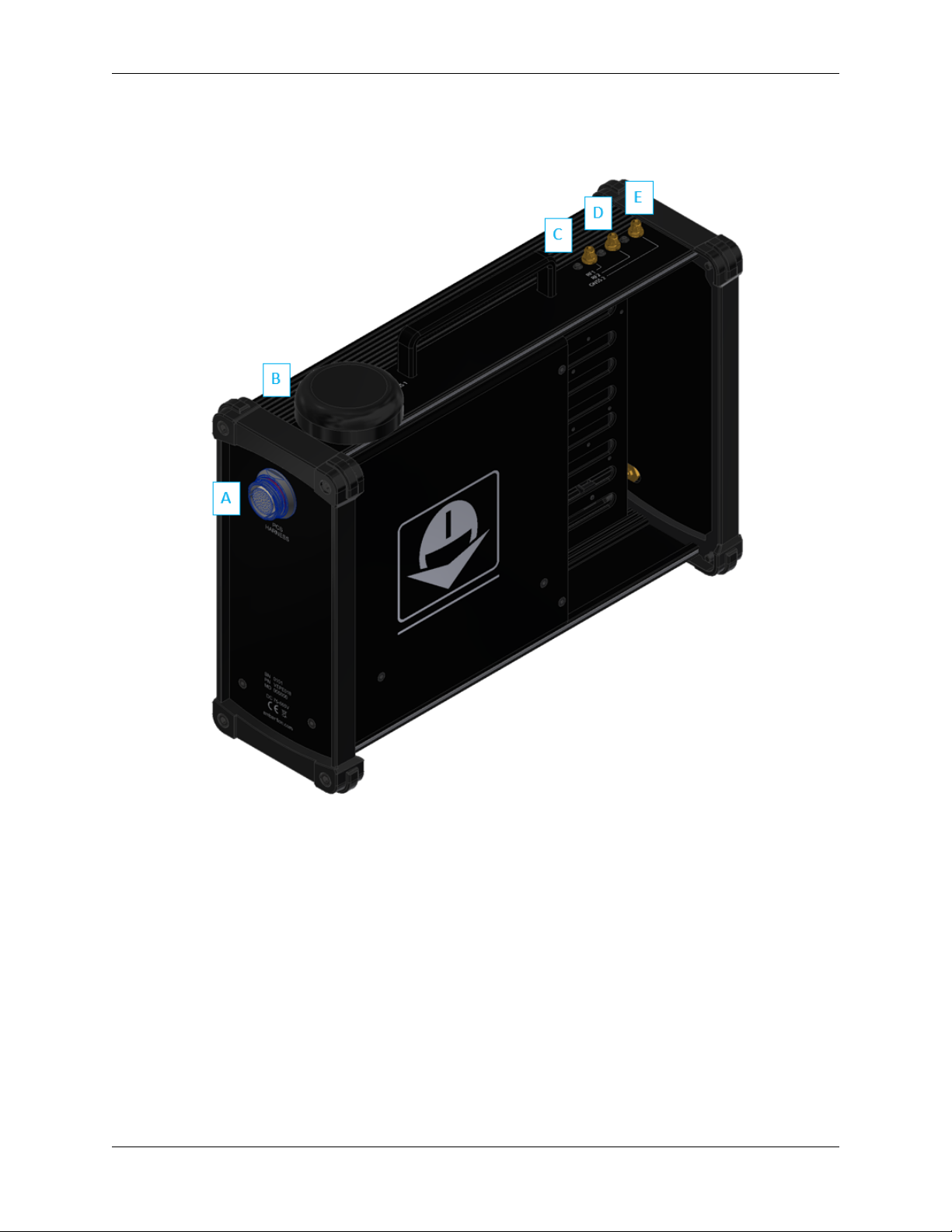
1.6 Interfaces
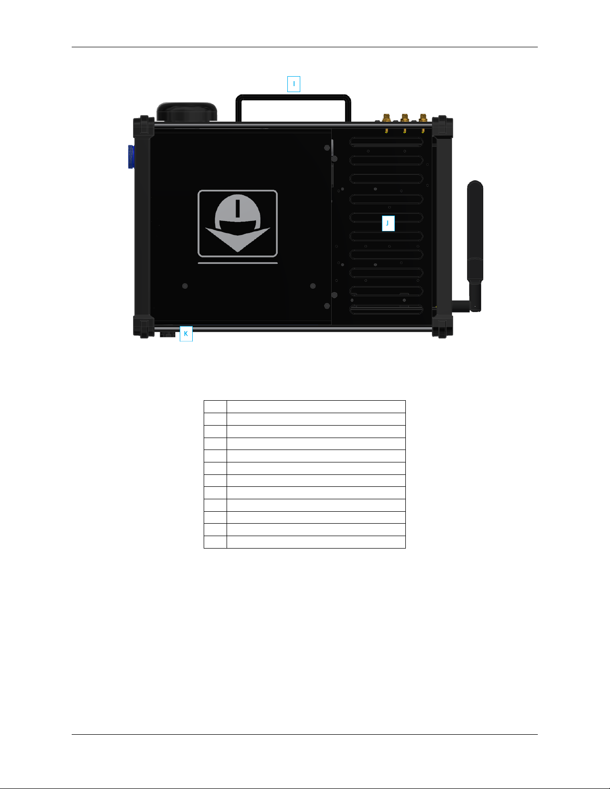
Fig. 4: PCS Interfaces - Parts identification
6 Chapter 1. Technical

Veronte PCS
Fig. 5: PCS Interfaces - Parts identification
1.6. Interfaces 7
Veronte PCS
Fig. 6: PCS Interfaces - Parts identification
ID Items
A PCS Harness connector
B Integrated GNSS antenna
C RF 1 antenna (SMA female)
D RF 2 antenna (SMA female)
E GNSS 2 antenna (SMA female)
F Connector for Expansion Bay
G Ethernet connector
H Wifi antenna connector (SMA female RP)
I Hand carrier
J Expansion Bay
K Automatic pressure purge
8 Chapter 1. Technical
Veronte PCS
1.7 Part list
The system consist of a multiple components listed below.
Quantity Items
1 Veronte PCS Control Station Unit
1 Pole and wall mounting accessories
1 Foldable mast
1 Connection harness
1 Veronte Control station Power source (euro plug)
1 5m ethernet extension cable
1 5m USB A extension cable
1 5m joystick extension cable
1 Expansion Bay Male Connector FGG.2B.316.CLAD72Z
1 Rugged transport case
1 High Gain Antenna
1 RF Cable - N Male to SMA - LMR-195 - 410mm
1 Datalink (not always, depending on variant)
1 Amplifier (not always, depending on variant)
1.7. Part list 9

Veronte PCS
10 Chapter 1. Technical

CHAPTER
TWO
INSTALLATION
2.1 ATTENTION
•Do not power on the PCS Ground Station without connecting the antenna.
•Do not start a mission without having a charged battery.
•Make sure the distance between ground end and air end is over 5m.
•Guarantee that no obstacles will interrupt Radiolink LOS.
•Port RS232 has possible connections in both external harnesses (68 pin) and Expansion Bay (16 pin). CAUTION:
only one of both can be used. They drive to the same input channel, but this configuration is thought to ease the
connection of any device from the Expansion Bay if needed.
•Port RS-485 is used by default by the Veronte BCS for Ethernet connection. Please contact us before using it for
other purposes.
•Only one dhcp device connection can be done simultaneously. If more than one is meant to be connected, then
it is needed to configure a Static IP, as established in Operation section.
•Veronte PCS is IP54 protected while closed. However, it loses its water resistance meanwhile the outer cover is
open.
•Do not break warranty seals. Please contact us before doing it.
•Keep the PCS in a position where the GPS antenna is facing to the free sky for better satellite view.
•Do not cover the pressure purge in order to ensure the correct flow of the system
•Avoid shocks during transportation or operation, some of the components could suffer damage.
Warning: For safer operations, it is recomended to operate the Veronte PCS connected to an external power
source, using the internal battery as back-up.
Warning: Do not forget to connect RF antenna before powering up!!!!
11

Veronte PCS
2.2 Basic Connection Diagram
Fig. 1: Basic Connection Diagram
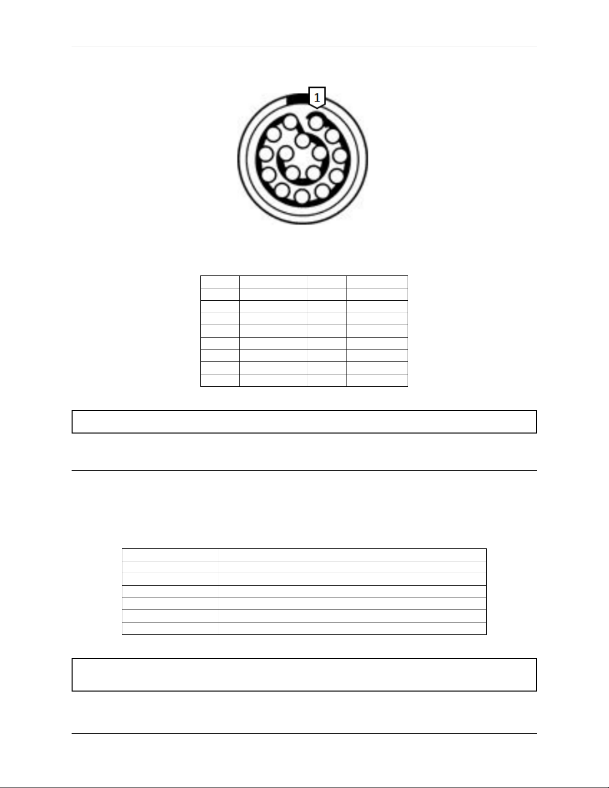
2.3 Pinout
PCS Harness connector
The 68 pin main connector has the distribution of input/output channels as follows:
12 Chapter 2. Installation

Veronte PCS
PCS Unit - Input pins
Pin nºFunction Pin nºFunction Pin nºFunction Pin nºFunction
1PWM 1 18 GND 35 GND 52 RS-485_RX-
2PWM 2 19 RS-232 TX 36 5V 53 RS-485_RX+
3PWM 3 20 RS-232 RX 37 GND 54 RS-485_GND
4PWM 4 21 Ethernet Tx+ (*) 38 ANALOG_1 55 Not used (*)
5PWM 5 22 ANALOG_4 39 ANALOG_2 56 Not used (*)
6PWM 6 23 Not used (*) 40 ANALOG_3 57 EQEP_S
7PWM 7 24 Ethernet Tx- (*) 41 Ethernet RX- (*) 58 EQEP_I
8PWM 8 25 CANA_P 42 FTS_1 59 GND
9GND 26 CANA_N 43 FTS_2 60 USB_DP
10 PWM 9 27 Not used (*) 44 Not used (*) 61 USB_DN
11 PWM 10 28 CANB_P 45 V_ARB_TX 62 Not used (*)
12 PWM 11 29 CANB_N 46 V_ARB_RX 63 Not used (*)
13 PWM 12 30 Ethernet Rx+ (*) 47 GND 64 Not used (*)
14 PWM 13 31 I2C_SCL 48 VCC (*) 65 GND
15 PWM 14 32 I2C_SDA 49 GND 66 GND
16 PWM 15 33 GND 50 RS-485_TX+ 67 VCC
17 PWM 16 34 3.3V 51 RS-485_TX- 68 VCC
Note: The functions marked with (*) differ from Veronte BCS Pinout
Warning: RS-485 bus is used by default by the Veronte BCS for Ethernet communications.
Expansion Bay Connector
For the Expansion bay connector, the pinout is shown below:
2.3. Pinout 13
Veronte PCS
PCS Unit - Output pins
Pin nºFunction Pin nºFunction
13.3V (Output) 9Not used (*)
2GND 10 Not used (*)
35V (Output) 11 Not used (*)
4GND 12 Not used (*)
512V (Output) 13 CANA_P
6GND 14 RS232-TX
724V (Output) 15 CANA_N
8GND 16 RS232-RX
Warning: RS-232 pins are common with the external pinnout.
The Expansion Bay mating connector is EGG.2B.316.CLL.
PCS Harness
The PCS Harness is a cable provided with the system which has many connectors to control the PCS ground station.
Next table describes the equipped connectors and its functionality.
Connector Description
FGW.LM.368.XLCT Main connector to PCS ground station
Ethernet Ready to connect an Ethernet cable to a Laptop or Veronte MCS
USB Type A Ready to connect to a Laptop or Veronte MCS
Joystick PPM input for Joystick
Push button ON/OFF button
Power source 24 VDC input
Warning: Do NOT connect the CS harness provided for other Veronte units. ONLY use PCS own Matting
connector.
Matting connectors to PCS harness
14 Chapter 2. Installation

Veronte PCS
Connector Standard
Ethernet Regular ethernet connector
USB USB female type A
Joystick HI-J35S-Screw-F
Power source PT06A-10-6S(005)
2.4 Mechanical installation
There are 2 separate accessories for the Veronte PCS in order to mount the unit on a mast or on the Veronte Tracker or
a wall.
The accessories are :
Pole Mount.
Fig. 2: Pole mount
Wall Mount
2.4. Mechanical installation 15

Veronte PCS
Fig. 3: Wall mount
The installation of the wall mount is described in the Veronte Tracker Manual.
Pole mount installation
The pole mount is composed by two aluminun brackets to assemble the PCS to the foldable mast.
To assemble the system follow the next steps:
1. Fix the two brackets to the PCS Control Station with 2mm allen screw driver.
16 Chapter 2. Installation
Table of contents
Popular Industrial Equipment manuals by other brands

Armorgard
Armorgard ducktrack DR1 user manual

PGR
PGR PA-PF Series Maintenance and operation instructions

Trelleborg
Trelleborg SCN 2250 Handling, Storage, Installation and Maintenance Manual

Gentec
Gentec Beamage M2 user manual

Stark
Stark 61041 manual

Wilo
Wilo Wilo-Flumen OPTI-TR 20-1 Installation and operating instructions


