Asco P152 Series User manual

INSTALLATION AND MAINTENANCE INSTRUCTIONS
P152 PLUS
SERIES
P152
Table of Contents
1. Notifications ...................................................................................................................................................... 3
1.1. Technical Support Contact .................................................................................................................................................................................3
1.2. Disclaimer ..................................................................................................................................................................................................................4
1.3. Symbols and Conventions ..................................................................................................................................................................................4
1.4. Safety ...........................................................................................................................................................................................................................5
2. Associated Documentation .............................................................................................................................. 6
2.1. Product Information ..............................................................................................................................................................................................6
3. Introduction ....................................................................................................................................................... 7
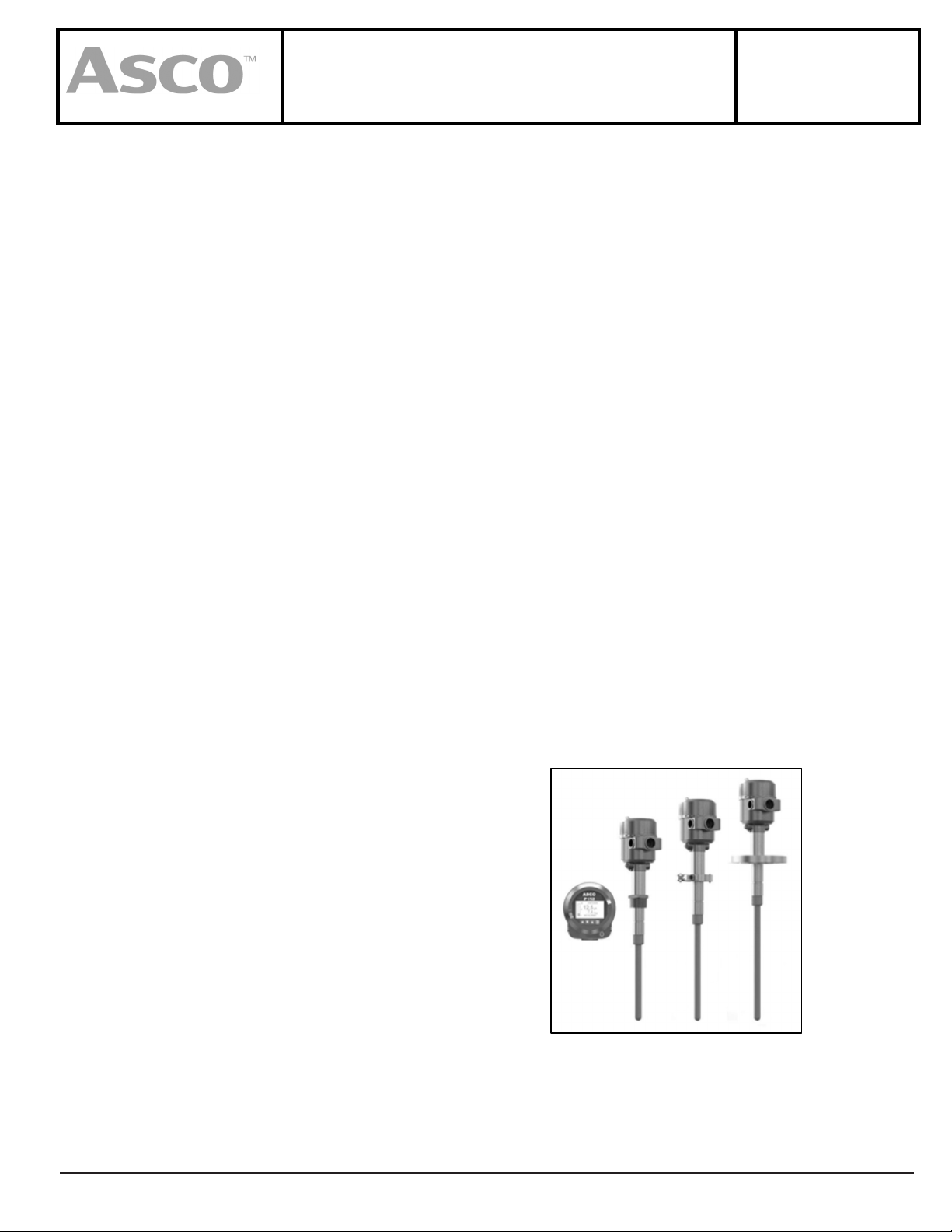
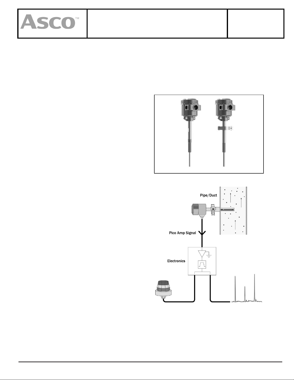
3.1. P152 PLUS Overview .............................................................................................................................................................................................7
3.2. Design .........................................................................................................................................................................................................................9
3.3. Components .......................................................................................................................................................................................................... 11
3.4. Technical Data ...................................................................................................................................................................................................... 12
4. Installation ....................................................................................................................................................... 15
4.1. Location................................................................................................................................................................................................................... 16
4.2. Process Mounts .................................................................................................................................................................................................... 18
4.3. Sensor Mounting ................................................................................................................................................................................................. 20
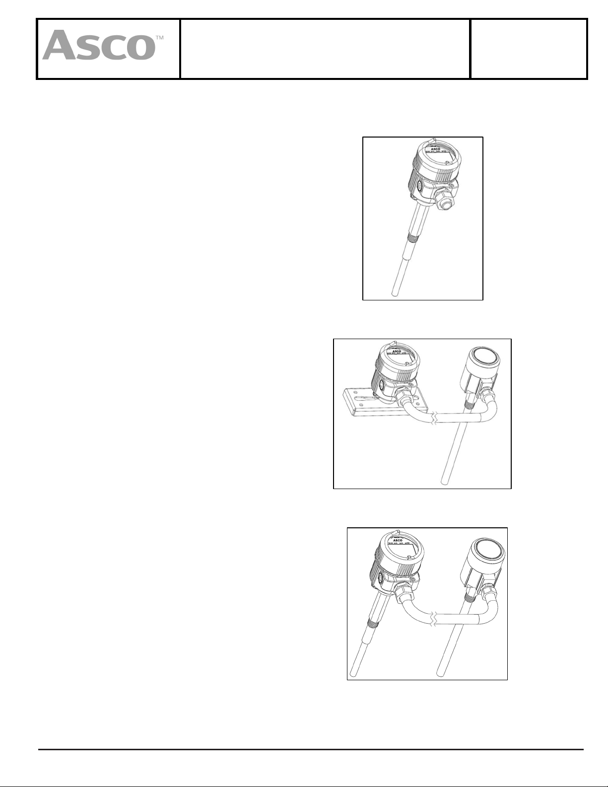
4.4. Remote Electronics Mounting ........................................................................................................................................................................ 22
4.5. Test Port .................................................................................................................................................................................................................. 23
5. Wiring ............................................................................................................................................................... 24
5.1. Terminal Connections........................................................................................................................................................................................ 25
5.2. HART Wiring .......................................................................................................................................................................................................... 29
5.3. Particulate Sensor Wiring (Remote Version Only) .................................................................................................................................. 30
6. Operation ......................................................................................................................................................... 31
6.1. User Interface ........................................................................................................................................................................................................ 31
6.2. Home Screen ......................................................................................................................................................................................................... 32
6.3. Process Screens .................................................................................................................................................................................................... 33
6.4. Active Alarm Screen ........................................................................................................................................................................................... 35
6.5. Alarm Details Screen .......................................................................................................................................................................................... 35
6.6. Diagnostic Screen ................................................................................................................................................................................................ 36
6.7. User Login .............................................................................................................................................................................................................. 36
6.8. Setup Menu ........................................................................................................................................................................................................... 37
7. Commissioning ................................................................................................................................................ 38
7.1. Measurement ........................................................................................................................................................................................................ 38
7.2. Alarms ...................................................................................................................................................................................................................... 39
7.3. Relay Outputs ........................................................................................................................................................................................................ 40
7.4. Analog Output ...................................................................................................................................................................................................... 40
7.5. Diagnostic Signaling .......................................................................................................................................................................................... 42
7.6. HART ......................................................................................................................................................................................................................... 42
7.7. Bluetooth and DeviceLINK Mobile App ...................................................................................................................................................... 53
7.8. Display ..................................................................................................................................................................................................................... 54
7.9. System ..................................................................................................................................................................................................................... 54
7.10. Information ............................................................................................................................................................................................................ 56
7.11. Alarm Setpoint Guidance ................................................................................................................................................................................. 56
8. Diagnostics....................................................................................................................................................... 58
8.1. Automatic Self-Checks ...................................................................................................................................................................................... 58
ASCO Valves® All Rights Reserved. I&M V_10026_AA
E406787 - 11/2023 www.emerson.com/ASCO Page 1 of 65

INSTALLATION AND MAINTENANCE INSTRUCTIONS
P152 PLUS
SERIES
P152
8.2. Device Diagnostics & NAMUR ......................................................................................................................................................................... 60
8.3. Functional Verification ...................................................................................................................................................................................... 61
8.4. Run Self-Checks .................................................................................................................................................................................................... 62
8.5. System Zero Check ............................................................................................................................................................................................. 62
8.6. Response Testing................................................................................................................................................................................................. 62
8.7. Factory Testing ..................................................................................................................................................................................................... 63
9. Troubleshooting .............................................................................................................................................. 63
10. Maintenance .................................................................................................................................................... 64
11. Spare Parts ....................................................................................................................................................... 65
11.1. Electronics Module Replacement ................................................................................................................................................................. 65
Page 2 of 65 I&M V_10026_AA
www.emerson.com

INSTALLATION AND MAINTENANCE INSTRUCTIONS
P152 PLUS
SERIES
P152
1. Notifications
1.1. Technical Support Contact
Emerson provides industry-leading Engineering and Technical Support for all product lines. The Technical Support department is
staffed with a team of engineering professionals. Areas of assistance provided by the Technical Support department include:
•Pre-Installation Site Analysis
•Product Installation
•General Operation
•Application-Specific Review
•Routine Calibration
•EPA Compliance
•Performance Upgrades and Add-On Features
To assure the best and most efficient technical support, please be prepared with the following information prior to contacting
Emerson. If it is determined that the component must be returned for evaluation/repair, a Return Material Authorization (RMA)
number will be issued. You must include the RMA number on the packing slip and mark the outside of the shipping container.
•Company Name
•Product Model Number
•Product Serial Number
•Date of Installation
•Reason for Return
Contact Regional Sales for Technical Support.
Notes:
•Any control unit or particulate sensor that was exposed to hazardous materials in a process must be properly cleaned in
accordance with OSHA standards, and a Material Safety Data Sheet (MSDS) must be completed before it is returned to the
factory.
•All shipments returned to the factory must be sent by prepaid transportation.
•All shipments will be returned F.O.B. factory.
•Returns will not be accepted without an RMA number.
Page 3of 65 I&M V_10026_AA
www.emerson.com

INSTALLATION AND MAINTENANCE INSTRUCTIONS
P152 PLUS
SERIES
P152
1.2. Disclaimer
This document contains important information necessary for proper operation of the product. It is strongly urged that all
users of the product read this manual in its entirety. All instructions should be followed properly and any questions that arise
should be discussed with Emerson.
Any use or distribution of this document without the express consent of Emerson is strictly prohibited. Any reproduction is
prohibited without written permission.
In no event will Emerson be liable for any mistake, including lost profits, lost savings, environmental compliance costs, or
other incidental or consequential damages or injury arising out of the use or inability to use this manual, even if advised of
the possibility of such damages, or any claim by any other party. Terms and conditions supplied with each order contain
additional liability limitations related to this product.
1.3. Symbols and Conventions
Identifies information about practices or circumstances that can lead to personal injury or death,
property damage, or economic loss.
Warning statements help you to:
•Identify a hazard.
•Avoid a hazard.
•Recognize the consequences.
Identifie les informations sur les pratiques ou les circonstances qui peuvent entraîner des blessures
corporelles ou la mort, des dommages matériels ou des pertes économiques.
Les avertissements vous aident à:
•Identifier un danger
•Évitez un danger
•Reconnaître les conséquences
Identifies information that is critical for successful application and understanding of the product.
Identifies information, sections, or statements in this manual that apply to approved hazardous area
systems, regulations, or installation.
Identifie les informations, sections ou déclarations de ce manuel qui s'appliquent aux systèmes,
réglementations ou installations approuvés pour zones dangereuses.
Page 4of 65 I&M V_10026_AA
www.emerson.com

INSTALLATION AND MAINTENANCE INSTRUCTIONS
P152 PLUS
SERIES
P152
1.4. Safety
AREA CLASSIFICATION (CLASSIFICATION DE ZONE)
Before installing any device, confirm area classification requirements as specified on the product
label. Do not install any device that is not tagged as suitable for the required area classification.
Avant d'installer un appareil, confirmez les exigences de classification de zone telles que spécifiées
sur l'étiquette du produit. N'installez aucun appareil qui n'est pas étiqueté comme adapté à la
classification de zone requise.
ENVIRONMENT (ENVIRONNEMENT)
Before installing any device, confirm ambient temperature, process temperature, and process
pressure requirements. Do not install any device that is not tagged as suitable for the required
temperatures and pressures.
Avant d'installer un appareil, vérifiez les exigences de température ambiante, de température de
processus et de pression de processus. N'installez aucun appareil qui n'est pas étiqueté comme
adapté aux températures et pressions requises.
NOT A SAFETY RATED DEVICE (PAS UN DISPOSITIF DE SÉCURITÉ ÉVALUÉ)
This model must not be used independently for safety or as a critical input signal to a safety system.
This model is designated for general process control, diagnostics, and environmental monitoring.
Safety must be addressed with the detailed engineering, redundancy, and safety certified
components where applicable. Consult factory for critical safety applications.
Ce modèle ne doit pas être utilisé indépendamment pour la sécurité ou comme signal d'entrée
critique vers un système de sécurité. Ce modèle est conçu pour le contrôle général des processus, les
diagnostics et la surveillance environnementale. La sécurité doit être abordée avec l'ingénierie
détaillée, la redondance et les composants certifiés de sécurité, le cas échéant. Consultez l'usine pour
les applications de sécurité critiques.
GROUNDING (MISE À LA TERRE)
Before turning on the instrument, you must connect the protective earth terminal of the instrument
to a proper earth ground. Grounding to the neutral conductor of a single-phase circuit is not sufficient
protection.
Avant de mettre l'instrument sous tension, vous devez connecter la borne de terre de protection de
l'instrument à une prise de terre appropriée. La mise à la terre du conducteur neutre d'un circuit
monophasé ne constitue pas une protection suffisante.
INSTALLATION AND SERVICE PERSONNEL (PERSONNEL D'INSTALLATION ET DE SERVICE)
Only appropriately licensed professionals should install this product. Always disconnect power
before servicing.
Personnel must be familiar with operational hazards, such as those caused by hot, pressurized, or
toxic gases, liquids, or particulates.
Service of individual electronics is limited to replacement of the electronics module. Do not attempt
to disassemble electronics. Any components that are not operating properly should be returned to
Emerson for service.
Seuls les professionnels agréés doivent installer ce produit. Débranchez toujours l'alimentation avant
de procéder à l'entretien.
Le personnel doit être familiarisé avec les dangers opérationnels, tels que ceux causés par des gaz,
des liquides ou des particules chauds, sous pression ou toxiques.
Page 5of 65 I&M V_10026_AA
www.emerson.com

INSTALLATION AND MAINTENANCE INSTRUCTIONS
P152 PLUS
SERIES
P152
L'entretien de l'électronique individuelle est limité au remplacement du module électronique.
N'essayez pas de démonter l'électronique. Tous les composants qui ne fonctionnent pas
correctement doivent être renvoyés à Auburn FilterSense pour réparation.
2. Associated Documentation
This manual is to be referenced in conjunction with the following Emerson documentation:
2.1. Product Information
Publication Number Title
564422-001 Particulate Sensor Model P152F/G/H Hardware Manual
564942 P152F/G/H Hazardous Area Wiring with P152 Electronics
564943 P152A/D Intrinsically Safety Wiring
EXXXX Project Specific Drawings if Applicable
Specific Conditions of Use:
1. When the manufacturer of the equipment has not identified the type of protection to be used for installation on the
label, the user shall, on installation, mark the label with the type of protection used. Once the type of protection has
been marked it shall not be changed.
2. The P152A shall be used with the EATON MTL5541 when installed in the hazardous area according to 564943.
3. NEMA 4X and IP66 ratings only apply to the P152F/G/H probe assembly when installed per drawing 564942.
4. The maximum permitted ambient temperature of the P152 Transmitter is 71 °C. To avoid the effects of process
temperature and other thermal effects care shall be taken to ensure the surrounding ambient and the ambient inside
the transmitter housing does not exceed 71°C
5. To prevent the risk of electrostatic sparking the painted surface of the enclosure should only be cleaned with a damp
cloth.
Conditions particulières d'utilisation :
1. Lorsque le fabricant de l'équipement n'a pas identifié le type de protection à utiliser pour l'installation sur l'étiquette,
l'utilisateur doit, lors de l'installation, marquer l'étiquette avec le type de protection utilisé. Une fois que le type de
protection a été marqué, il ne doit pas être modifié.
2. Le P152A doit être utilisé avec l'EATON MTL5541 lorsqu'il est installé dans la zone dangereuse conformément à
564943.
3. Les indices NEMA 4X et IP66 s'appliquent uniquement à l'ensemble de sonde P152F/G/H lorsqu'il est installé
conformément au schéma 564942.
4. La température ambiante maximale autorisée du transmetteur P152 est de 71 °C. Pour éviter les effets de la
température du processus et d'autres effets thermiques, il faut veiller à ce que la température ambiante et la
température ambiante à l'intérieur du boîtier du transmetteur ne dépassent pas 71 °C.
5. Pour éviter le risque d'étincelles électrostatiques, la surface peinte du boîtier ne doit être nettoyée qu'avec un
chiffon humide.
Page 6of 65 I&M V_10026_AA
www.emerson.com

INSTALLATION AND MAINTENANCE INSTRUCTIONS
P152 PLUS
SERIES
P152
3. Introduction
3.1. P152 PLUS Overview
P152 PLUS
The P152 PLUS is a single-point, advanced functionality, high performance, and heavy-duty particulate monitor employing charge
induction/electrodynamic sensing for reliable monitoring of particulate in stacks, ducts, and pipes. Applications include continuous
particulate emissions monitoring, filter performance monitoring, leak detection, cyclone overflow detection, powder flow trending
and flow/no flow indication. Advanced functionality and high performance/reliability make the instrument ideally suited for Industry
4.0, IIoT (Industrial Internet of Things) and optimizing plant performance.
Available Features include:
•Advanced communication options
oHART with DTM and Modbus
•State of the art low power/loop powered design including:
oHigh speed DSP for high accuracy and low-level measurement
oAutomatic zero, span, sensor, and device health checks
oInternal data logging with high accuracy time clock
•Advanced dynamic charge induction sensing.
•Fully insulated sensing probes for reliable operation in moist, corrosive, and conductive applications
EPA Compliance
The P152 PLUS is a value-added solution for EPA compliance. The instrument can meet different levels of measurement and
monitoring including EN 15859, ASTM D7392 and US-EPA MACT including self-testing and quality assurance requirements. The
product employs the latest generation of Emerson TUV QAL 1 approved technology.
Optional equipment and proper configurations may be required to meet a specific compliance regulation. Consult the factory for an
application review.
Versions
The P152 PLUS is available in three versions.
•P152A (Transmitter, Loop Powered)
o2-Wire Loop Powered Transmitter (4-20mA, HART
Optional)
oIntegral or Remote Electronics
oGraphical Display/Keypad
•P152C (Alarm and Transmitter)
oAlarm Relays and Transmitter (powered 4-20mA,
HART Optional) or Serial (Modbus or Profibus)
oIntegral or Remote Electronics
oGraphical Display/Keypad
•P152B (Alarm Only)
oAlarm Relay Outputs
oIntegral or Remote Electronics
oGraphical Display/Keypad
Page 7of 65 I&M V_10026_AA
www.emerson.com

INSTALLATION AND MAINTENANCE INSTRUCTIONS
P152 PLUS
SERIES
P152
P152 BASIC
The P152 is also available in a lower priced basic version.
Refer to P152 BASIC manual.
•P152E (Alarm Only)
oAlarm Relay Outputs Only
oIntegral Electronics Only
•P152D (Transmitter, Loop Powered)
o2-Wire Loop Powered 4-20mA
oIntegral Electronics Only
•Refer to the P152 BASIC manual or contact Regional
Sales for more information.
Principle of Operation
The principle of operation is dynamic charge induction
(electrodynamic).
As particles flow near or over the electrically isolated sensing
probe, minute charge is dynamically induced and transferred
into the probe. The charge flows through a measurement circuit
to ground.
The signal is digitally filtered to principally measure the induced
charge and is further processed to provide an output that is
linear to mass. The unit of measure is picoamperes (pA). For
highest accuracy and highest linearity to mass, refer to the
model P150B/C.
The device also analyses aspects of the raw signal to provide
device and performance diagnostics.
For best understanding of particulate levels, 4-20mA analog
outputs should be converted to pA at remote recording devices
or remote displays. For output in mg/m3 or gs/cf the P150B/C is
recommended.
Page 8of 65 I&M V_10026_AA
www.emerson.com

INSTALLATION AND MAINTENANCE INSTRUCTIONS
P152 PLUS
SERIES
P152
3.2. Design
Integral Electronics
•Integral electronics for accessible locations
•Electronics and display are integral to the particulate
sensor.
Remote Electronics
•Remote electronics for hard-to-access locations and
very high-temperature applications
•Electronics and graphical display are mounted
separately from the particulate sensor
•Requires P152F/G/H particulate sensor and coaxial
cable (P850AC0000B)
Integral Electronics with Daisy Chain Sensor
•Integral electronics for accessible locations
•Daisy chain design for additional sensing coverage
across large ducts
•Requires P152F/G/H particulate sensor and coaxial
cable (P850AC0000B)
Page 9of 65 I&M V_10026_AA
www.emerson.com

INSTALLATION AND MAINTENANCE INSTRUCTIONS
P152 PLUS
SERIES
P152
Remote Electronics with Daisy Chain Sensor
•Remote electronics for hard-to-access locations and very
high-temperature applications
•Daisy chain design for additional sensing coverage across
large ducts
•Requires multiple P152F/G/H particulate sensors, coaxial
cable (P850AC0000B), and Daisy Chain Type Connector
(P850AC0000D)
Flexible Display/UI Module
•The P152 PLUS Display/UI Module can be inserted or
removed at any time.
•It is not necessary to disconnect power before removing
the Display Module.
•The P152 PLUS will continue to function and remain
powered when the display has been removed.
•Four module positions are possible, each displaced by
90°.
•The enclosure can be rotated 360° to accommodate all
installation orientations.
•The rotatable enclosure allows easy removal of threaded
sensors without the need to remove wiring and conduit.
Page 10 of 65 I&M V_10026_AA
www.emerson.com

INSTALLATION AND MAINTENANCE INSTRUCTIONS
P152 PLUS
SERIES
P152
3.3. Components
The P152 PLUS consists of the following main elements:
①Display/UI Module
②Electronics Module
③Enclosure
④Sensor Nipple/Process Mount
⑤Sensing Probe
①
②
③
④
⑤
Page 11 of 65 I&M V_10026_AA
www.emerson.com

INSTALLATION AND MAINTENANCE INSTRUCTIONS
P152 PLUS
SERIES
P152
3.4. Technical Data
Product Code Example
P152D 0 S A A B 0 C F 1 C
Display/UI Module
Rotatable Design 4 x Possible Display Orientations
Electronics Module
Parameter Detail/Code Specifications Notes
Display P152A/B/C Wide temperature, low power
2.7 in High-Resolution Monochrome
Rotatable Design, 4 x
Possible Display
Orientations
LEDs -P152B
-P152C 4 x LEDs for Power, Alarms 1 & 2, and Communication
Parameter Detail/Code Specifications Notes
Measurement
Technology
Charge Induction/electrodynamic
Measurement Units Picoamperes (pA) 1 x 10
-12
A
Input Voltage P152B or P152C
P152A
Universal 20-250 VAC/VDC, 47-63 Hz
Fuse: 1.0A, Slow-Blow 250V, Type ’T’
18-32 VDC Loop Power
Input Power P152B or P152C 3 Watts Max.
Electronic Resolution,
Range (8
th
digit)
D
A
B
C
Special - Monitoring, Resolution: 0.1 pA, Range: 0 to
5,000 pA, Requires Automatic EPA Self-Checks (N-K
Order Code)
0.5pA, Range 0 to 5,000pA
5.0pA, Range 0 to 5,000pA
10.0pA, Range 0 to 100,000pA Powder Flow Only
Minimum Particle
Size
0.3 Micron
Temperature
Ambient
-40 °F to +160 °F (-40 °C to +71 °C)
-40 °F to +185 °F (-40 °C to +85 °C)
Operating
Storage
Relay Outputs P152B or P152C Form A (SPST)
250 VAC/1A (Resistive), 1A (Inductive)
30 VDC/1A (Resistive), 1A (Inductive)
Type
Max Ratings
4-20mA Output P152A
P152C
500Ω Max. Loop Impedance @ 24 VDC Loop Power
500Ω Max. Loop Impedance @ 20 VDC Sourced Current
Output
Adjustable via Keypad
Rating
Rating
Span
Electronics Version P152A/B/C/D/E
P152A/B/C/D/E
W/O probe
Integral
Remote (Requires coaxial cable & P152F/G/H)
Area Classification &
Enclosure (9
th
digit)
E
F
Ordinary/General Purpose, (UL, CSA, CE) &Type 4X/IP 66
Aluminum, Powder Coated with Window
Hazardous Location, Class II, Division 2 (Zone 1, 2, 21,
22), Groups A-G, T4, (UL, CSA, ATEX, IECEx). Integral or
“G” & “K” is P152A
Integral Only
Page 12 of 65 I&M V_10026_AA
www.emerson.com

INSTALLATION AND MAINTENANCE INSTRUCTIONS
P152 PLUS
SERIES
P152
G
H
J
K
Remote Electronics & Type 4X/IP 66 Aluminum, Powder
Coated with Window
Hazardous Location, Class I, II, Division 1, 2 (Zone 0, 1, 2,
20, 21, 22), Groups A-G, T4, (UL, CSA, ATEX, IECEx),
Includes External Approved Safety Barrier, Wired
According to CONTROL DRAWING: 564943. Type
4X/IP 66 Aluminum, Powder Coated with Window
Ordinary/General Purpose, (UL, CSA, CE) & Type 4X/IP 66
Aluminum, Powder Coated with Window, Remote
Electronics Version (Pending)
Hazardous Location, Class II, Division 2 (Zone 1, 2, 21,
22), Groups A-G, T4, (UL, CSA, ATEX, IECEx). Integral or
Remote Electronics & Type 4X/IP 66 Aluminum, Powder
Coated with Window, Remote Electronics Version
(Pending)
Hazardous Location, Class I, II, Division 1, 2 (Zone 0, 1, 2,
20, 21, 22), Groups A-G, T4, (UL, CSA, ATEX, IECEx),
Includes External Approved Safety Barrier, Wired
According to CONTROL DRAWING: 564943. Type
4X/IP 66 Aluminum, Powder Coated with Window,
Remote Electronics Version (Pending)
Page 13 of 65 I&M V_10026_AA
www.emerson.com

INSTALLATION AND MAINTENANCE INSTRUCTIONS
P152 PLUS
SERIES
P152
Sensor Probe
Parameter Detail/Code Specifications Notes
Base Sensor (10
th
digit)
A
D
E
F
G
H
J
K
L
M
N
P
Special - NPT Male, 0.5 in., 316L
NPT Male, 1.5 in., 316L
BSPP (G) Male, 1.5 in., 316L
BSPT (R) Male, 1.5 in, 316L
Special - Quick Clamp, 1.5 in., 316L
Quick Clamp, 2.0 in, 316L
Flange, ANSI, 2.0 in, 150#, 316L
Flange, DIN 50, PN 10, 316L
Special - ANSI Flange, 316L, XX = Flange Size (25
=2.5 in), Y = Class (1 = 150#, 3 = 300#, 6 = 600#)
Special - DIN Flange, 316L, XXX = Flange Size
(DN) (80, 100 125), YY = Pressure Rating in Bar
(PN) (6,10)
Advanced Internal Air Purge (Must Select Quick
Clamp 2.0 in.)
Advanced Internal Air Purge (Must Select Flange
Nipple Assembly Above)
XX – Size (in)
Y – Pressure Rating (Bar)
Probe Type
(14
th
digit)
1
2
3
Bare, 316L Stainless Steel (Hastelloy C276 and
C22 Available)
Special - Fully Insulated, Teflon Coated, 316L
Fully Insulated, Teflon Layer, 316L
Layered only valid for
temperatures < 450F,
Coated or Layered
cannot be used with
used hazardous area
(F/G/J/K at 9
th
digit)
Coated Only for
P152D/E, Coated for
100 PSI or 500F,
otherwise use Layered
Process Temperature
Operating Range &
Process Pressure
Operating Range
(12
th
digit)
A
B
D
E
-40 °F to 250 °F (-40 °C to 121 °C) & Full vacuum to
10 PSI (0.69 Bar)
-40 °F to 450 °F (-40 °C to 232 °C) & Full vacuum to
10 PSI (0.69 Bar)
-40 °F to 250 °F (-40 °C to 121 °C) & Full vacuum to
100 PSI (6.9 Bar) - Excludes 0.5" Thread and 1.5"
QC
-40 °F to 450 °F (-40 °C to 232 °C) & Full vacuum to
100 PSI (6.9 Bar) - Excludes 0.5" Thread and 1.5"
QC
450°F CANNOT be used
hazardous area (F/G/J/K
at 9
th
digit)
For Higher Temperature
and Pressure, Refer to
Remote P152F/G/H
Note: unless specified, the rest digits are kept “0” as default.
Page 14 of 65 I&M V_10026_AA
www.emerson.com

INSTALLATION AND MAINTENANCE INSTRUCTIONS
P152 PLUS
SERIES
P152
4. Installation
•Only trained professionals should install/maintain this product.
•Shutdown processes that include high temperatures, high pressures, toxic gases, hazardous
particulate, or explosion risks prior to installing or removing equipment.
•Seuls des professionnels qualifiés doivent installer / entretenir ce produit.
•Arrêtez les processus qui incluent des températures élevées, des pressions élevées, des gaz
toxiques, des particules dangereuses ou des risques d'explosion avant d'installer ou de
retirer l'équipement.
Page 15 of 65 I&M V_10026_AA
www.emerson.com

INSTALLATION AND MAINTENANCE INSTRUCTIONS
P152 PLUS
SERIES
P152
4.1. Location
Area Classification
•Do not install any device that is not tagged as
suitable for the required area classification.
•Check label for the following:
oArea classification
oCertification numbers as required.
•FM23NUS0011
•FM23NCA0008
•FM23ATEX0035X
•FM23ATEX0034X
•FM23US0070X
•FM23CA0052X
•IECEx FMG 23.0017X``````
Hazardous Area Label Example `
Temperature and Pressure
•Confirm compatibility of pressure and temperature
ratings with process and installation area.
•Check label for the following:
oProcess temperature rating
oProcess pressure rating
Hazardous Area Side Label Examples
Intrinsically Safe Side Label Examples
Page 16 of 65 I&M V_10026_AA
www.emerson.com

INSTALLATION AND MAINTENANCE INSTRUCTIONS
P152 PLUS
SERIES
P152
The following factors should be considered:
•Confirm compatibility of all sensor ratings with process and installation area.
•Check label for the following:
oWetted materials
oEnclosure rating
•Installation must be in grounded metal duct/pipe. Consult factory for non-metallic duct/pipe solutions.
•High levels of vibration should be avoided.
Filter Outlet Locations
①
Ensure good access.
②
Avoid locating within one pipe diameter or 36
inches of vertical stack exit to protect against
weather. Horizontal exits allow for closer placement
to open weather.
③Straight runs and laminar flow best for
measurement.
④Short straight runs are acceptable for basic
monitoring.
⑤Accessible negative pressure locations may be
preferred to prevent exposure to toxic gases and
particulate.
Straight Run Considerations
•Straight runs meeting the following criteria are
preferred but not required for basic monitoring.
•Three (3) duct diameters upstream.
•Two (2) duct diameters downstream.
•Straight run can be horizontal or vertically downward
(as shown in illustration).
④
③
⑤
①
⑤
③
②
Page 17 of 65 I&M V_10026_AA
www.emerson.com

INSTALLATION AND MAINTENANCE INSTRUCTIONS
P152 PLUS
SERIES
P152
Powder Flow Locations
①
Best installed in pneumatic section (positive or negative
pressure).
②For gravity feed, consult factory.
•Grounded metal duct required.
oConsult factory for nonmetallic duct/ pipe
solutions.
•Follow straight run considerations.
Horizontal Pipes/Ducts
•Side or top mount recommended.
•Bottom mount not recommended.
•Proper mount and installation location will
prevent buildup.
•For further installation advice please contact
Regional Sales.
4.2. Process Mounts
The following types of process mounts are available:
Threaded
•NPT Standard
•BSPP (G) and BSPT ® Optional
①Threaded Nipple
②Threaded Coupling Process Mount
①
②
①
②
Page 18 of 65 I&M V_10026_AA
www.emerson.com

INSTALLATION AND MAINTENANCE INSTRUCTIONS
P152 PLUS
SERIES
P152
Quick Clamp
•Quick Clamp Standard
•Allows quick and easy removal from process
•Allows rotation to easily align
①Quick Clamp Nipple
②Quick Clamp Process Mount Kit
•Ferrule
•Gasket
•Tri-clamp
Flange
•ANSI Standard
•DIN Optional
①Flange Nipple
②Flange Process Mount
①
②
①
②
Page 19 of 65 I&M V_10026_AA
www.emerson.com

INSTALLATION AND MAINTENANCE INSTRUCTIONS
P152 PLUS
SERIES
P152
4.3. Sensor Mounting
Sensor Mounting Considerations
①
Process mount should protrude into process
0.125 in (3.175 mm) to 0.5 in (12.7 mm).
②Sensor probe should extend approximately
½1/2 of the duct diameter for stacks and filter
ducts a¼1/4 ½1/2 of the pipe diameter for
powder flow applications.
•In very large stacks/ducts, two sensors in a
daisy chain configuration can be considered.
•In smaller pipes, the probe should be at least 1
in (25.4 mm) minimum away from the opposite
side.
•High levels of vibration should be avoided.
②
②
①
①
②
①
Page 20of 65 I&M V_10026_AA
www.emerson.com
Other manuals for P152 Series
1
This manual suits for next models
1
Table of contents
Other Asco Industrial Equipment manuals