Item No.
Production
Part No. Qty. Description
1398318 1Support Primer Tube
2398356 1Tube Primer Pickup, Large
3398355 1Tube Primer Pickup, Small
4398358 1Tube Primer, Large
5398357 1Tube Primer, Small
6398322 1Housing Tube Primer
7392220 1Screw, BHCS 1/4-20 X 1/2
8399686 1Lock-N-Load®AP Bracket
9392342 1SHCS SS 3/8-16 X 3/4
10 398359 1Primer Follower
11 392338 1Screw, SHCS 10-24 X 1/2
12 —Shell Plate (Sold Separately)
13 392455 1Bracket Box Cartridge
14 398319A 1Housing Body Primer Tube
15 392218 1Primer Slide, Large Assembly
15 392219 1Primer Slide, Small Assembly
16 392336 1Spring Primer Slide
17 392363 1Spring Case Retainer
18 398695 1AP Breakaway Cam Wire
19 398698 1Nut, 8-32
20 190216 1Frame
21 392368 6Clip C, C-50
22 480039 1Box Catcher
23 392408 2Lock-N-Load®AP™Link
24 398309T 1Sub Plate
26 398505 1Primer Seater Punch, Small
26 398507 1Primer Seater Punch, Large
27 392467 1Counter Balance Spring
28 392345 13/8 Flat Washer SS
29 392355 1Drive Hub
Item No.
Production
Part No. Qty. Description
30 392356 1Drive Shaft
31 392231 2Screw, BHSCS 8-32 X 3/8
32 392344A 2Pawl
33 392423 2Spring Pawl
34 392306 2Dowel Pin 1/8 X 1/2
35 392221 2Screw, FHCS 1/4-28 X 3/8
36 290029 1Spent Primer Tube
37 398163 1Ram Assembly
38 398422 3Grease Zerk™
39 392343 1Toggle
40 392340 1Pin Yoke
41 392424 5Spring Washer
42 392417 2Pin Link Toggle
43 390027 1Nut Jam, 5/8-18
44 390657 1Handle
45 480003 1Knob
47 392358A 1Index Wheel
48 390081 2Clip E 1/2
49 392302 5Lock-N-Load®Bushing, Male
50 392303 5Lock-N-Load®Bushing O-Ring
51 392301 5Lock-N-Load®Bushing, Female
52 398697 1Breakaway Cam Plunger
53 398696 1Breakaway Cam Wire Spring
54 399853 1 Spent Primer Hose Clamp
55 392365 1 Spent Primer PVC Tube
56 399850 1 Spent Primer Bottle Barbed Fitting
57 399851 1 Spent Primer Bottle Cap
58 399852 1 Spent Primer Bottle
—9987 1DVD
Lock-N-Load®Auto Progressive (AP) Reloading Press
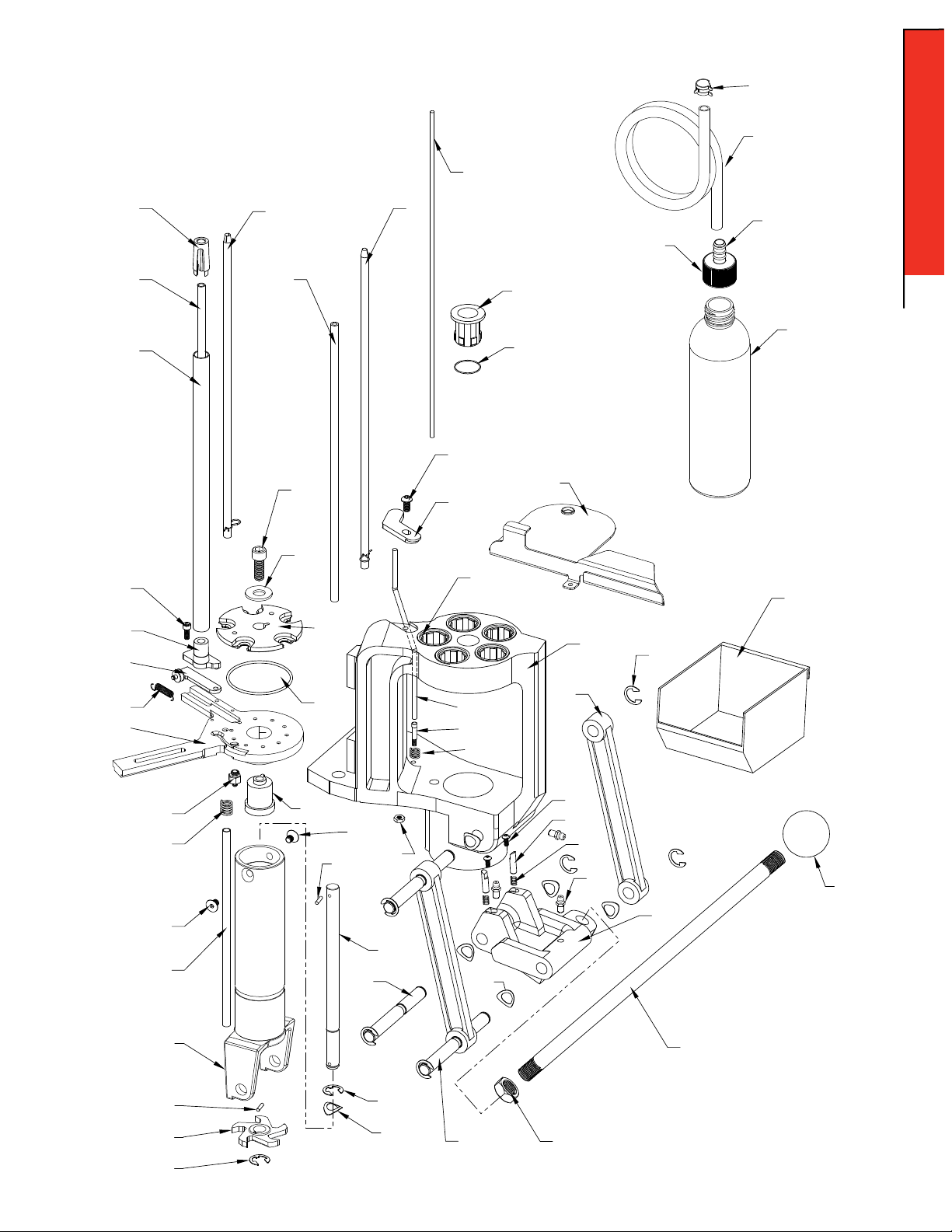
PARTS LIST
No-Risk Lifetime Warranty
All Hornady reloading tools and accessories are warranted against material defects and workmanship
for the life of the product. Simply stated – if it breaks, we’ll repair it or replace it at no charge
(at Hornady Manufacturing Company’s option).
Hornady reloading tools and accessories are warranted against defective materials and workmanship
only. This warranty is void if the product (1) has been damaged by accident or unreasonable use, neglect, improper service or other
causes not arising out of defects in material or workmanship; or (2) has been altered or repairs have been made or attempted by
other than authorized factory personnel; (3) is used commercially; or (4) has been altered or defaced in any way.
This warranty supersedes all other warranties for Hornady products either written or oral. No other warranty is expressed or implied.
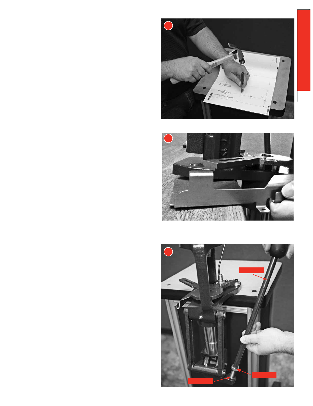
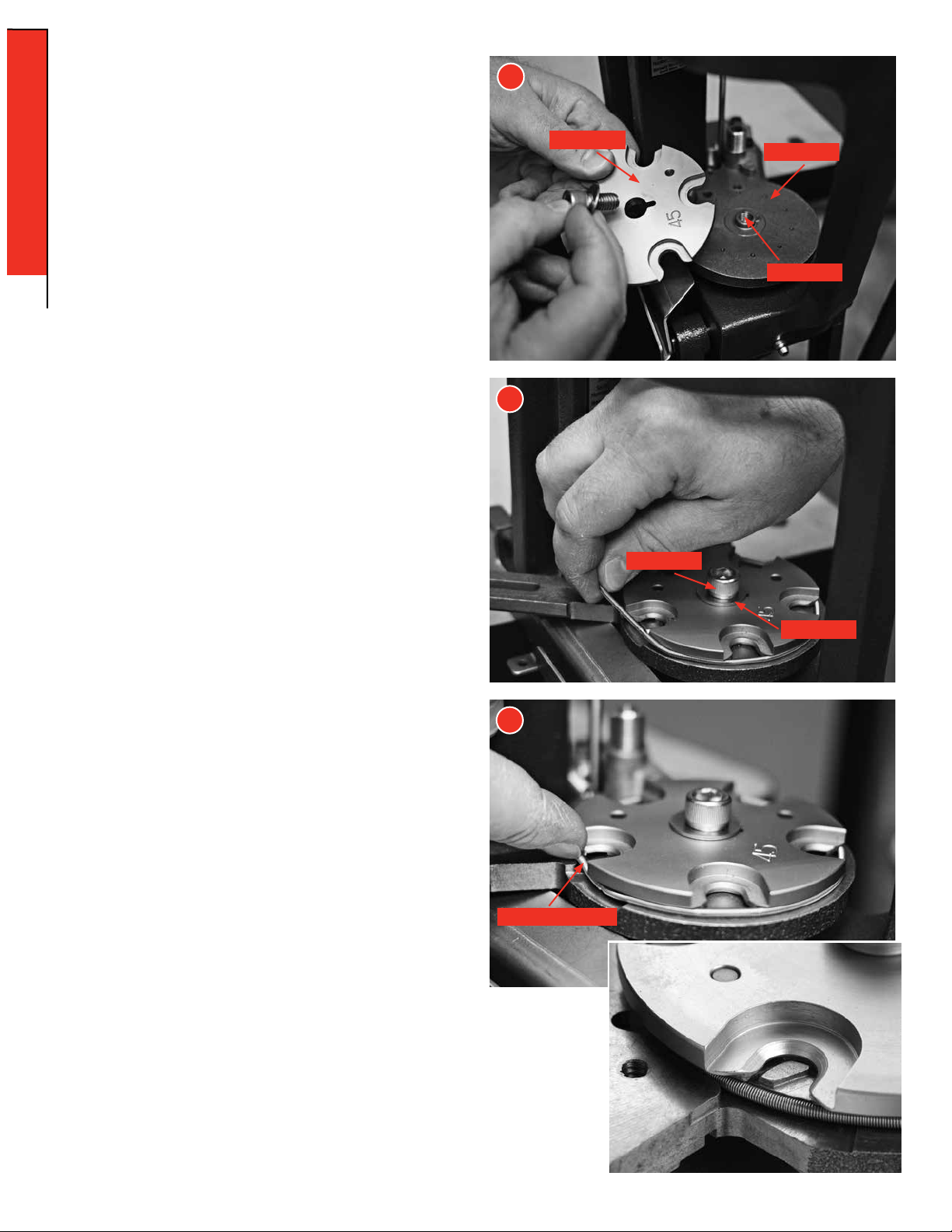
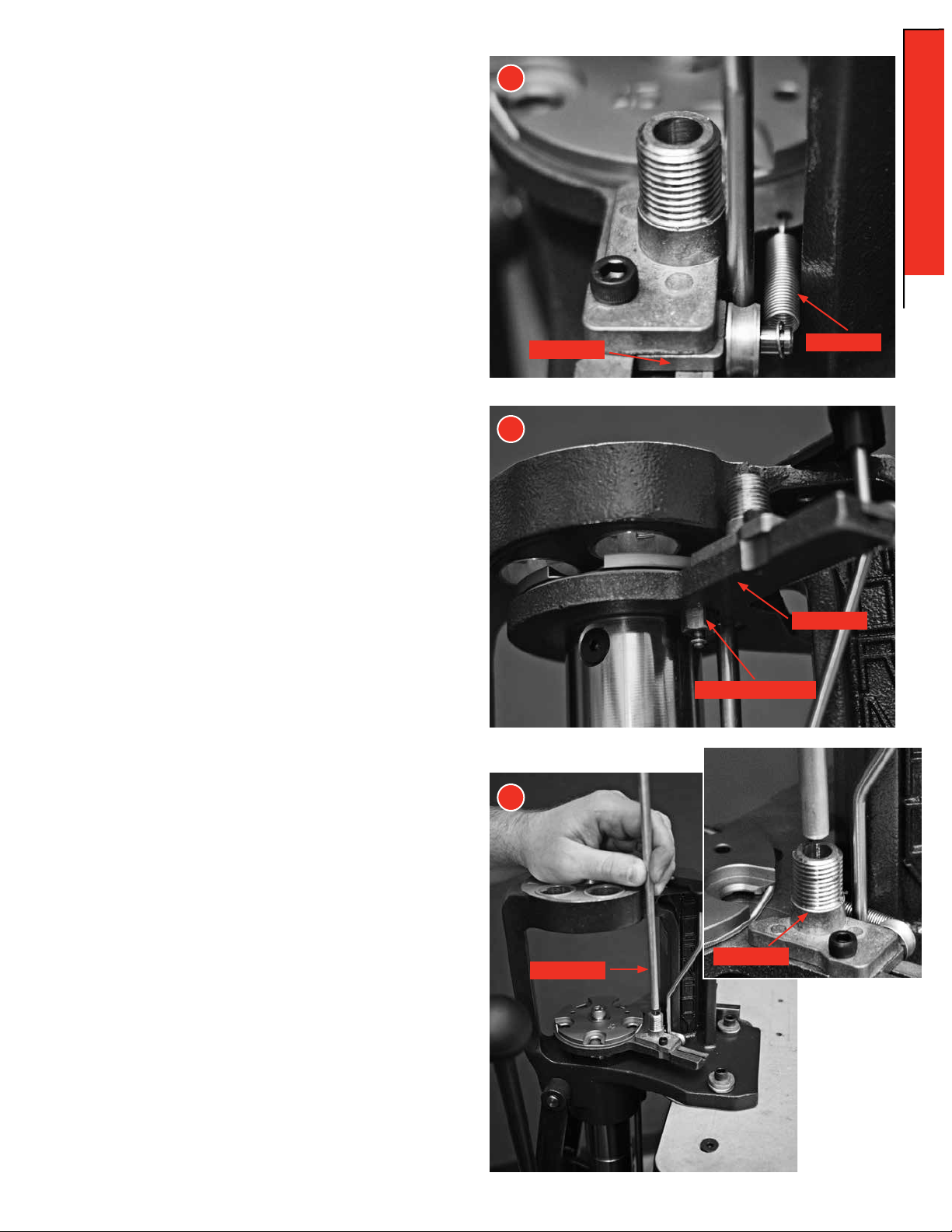
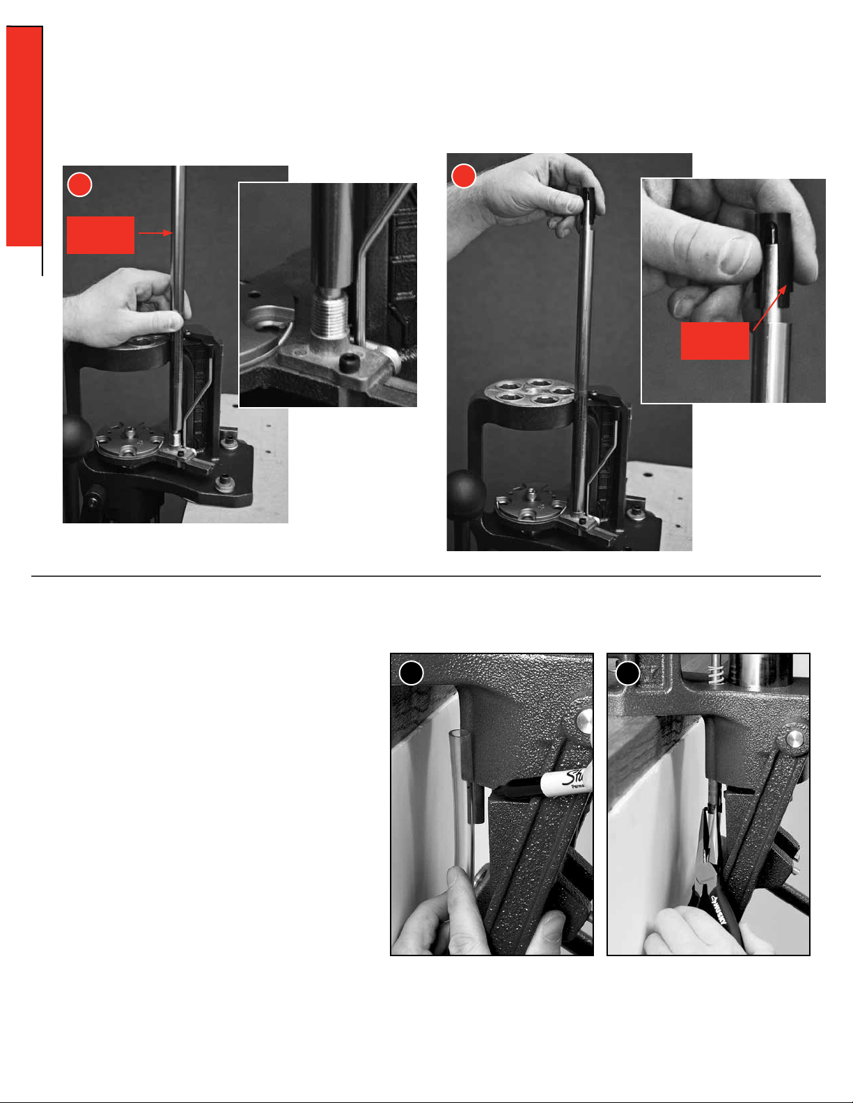
- 4 - ASSEMBLY: AP PRESS
ASSEMBLY