EMC INDUS RIAL GROUP L D Specifications
MW61A_IM_ALL_SV6.09d_en 6/47
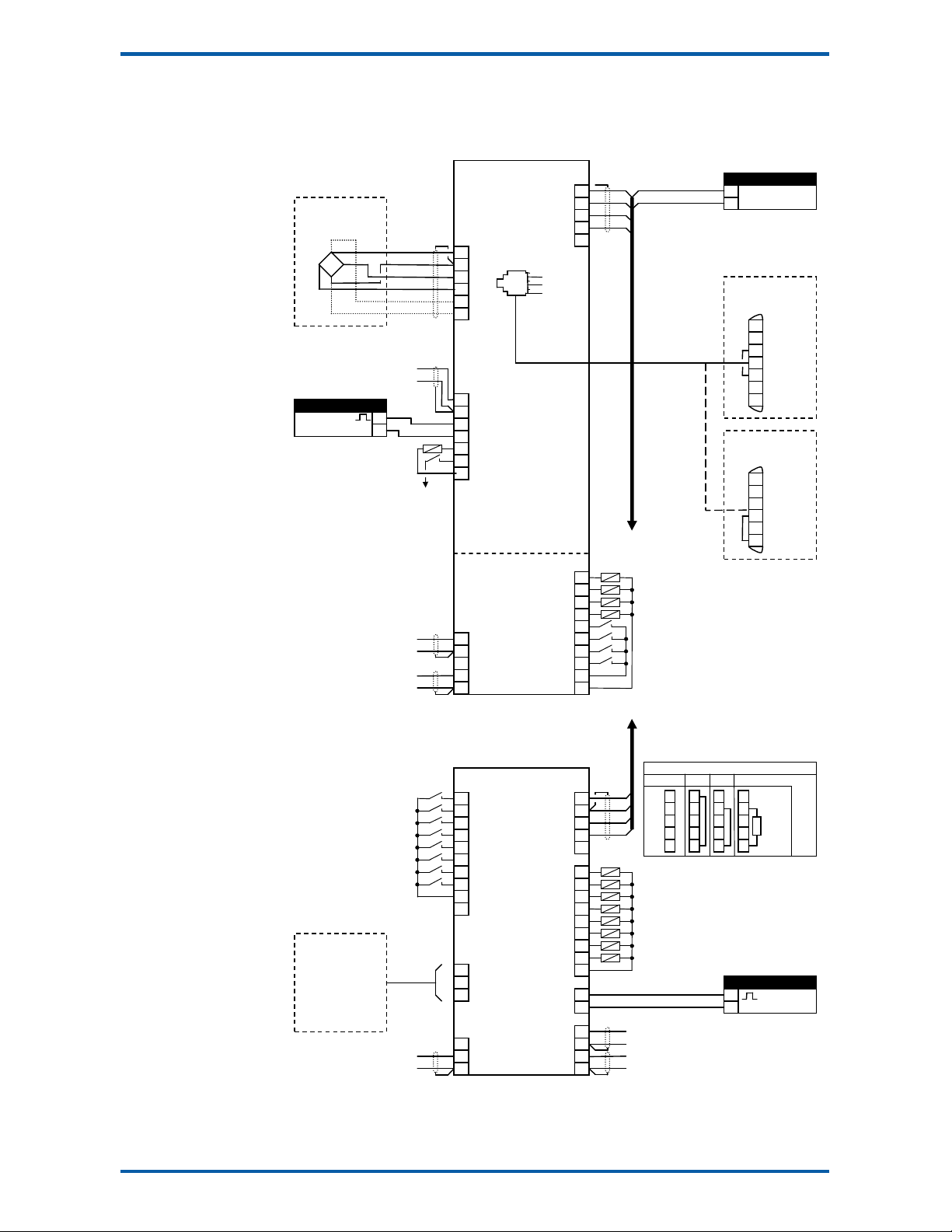
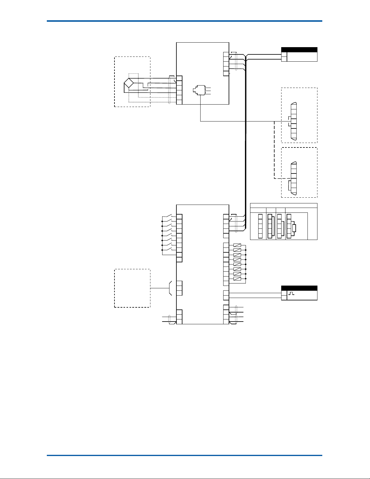
Digital Outputs OU x
The igital outputs are programmable to operate from any internal signal. These signals inclu e the
igital input states, status con itions (running, pause etc) an any fault con itions that are etecte .
This makes it easy connect into other systems.
Communications & Display
Comms
RS232 an RS485 ports are available. These are use to connect Mo Weigh units together an also to
connect to other systems. The protocol is either ASCII output for example to rive a printer or Mo bus
for interactive communications. Bau rates an no e a resses are programmable.
USB host an evice ports are available. This allows for example PC an USB flash rive connectivity. It
can be use to up ate the units software, for ata logging an for recor ing of the units settings.
Printouts & Macros
Printouts can be triggere by a key press or set up to occur at set times uring the ay or week. Data
may also be output continuously for ata collection purposes. Data is output on the COM1 RS232 port.
The content of the printouts is fully programmable using Macros.
Macros are programs use to customise printouts, but can also be use to perform arithmetic calcula-
tions. The Macro language also contains con itional terms for more a vance programming.
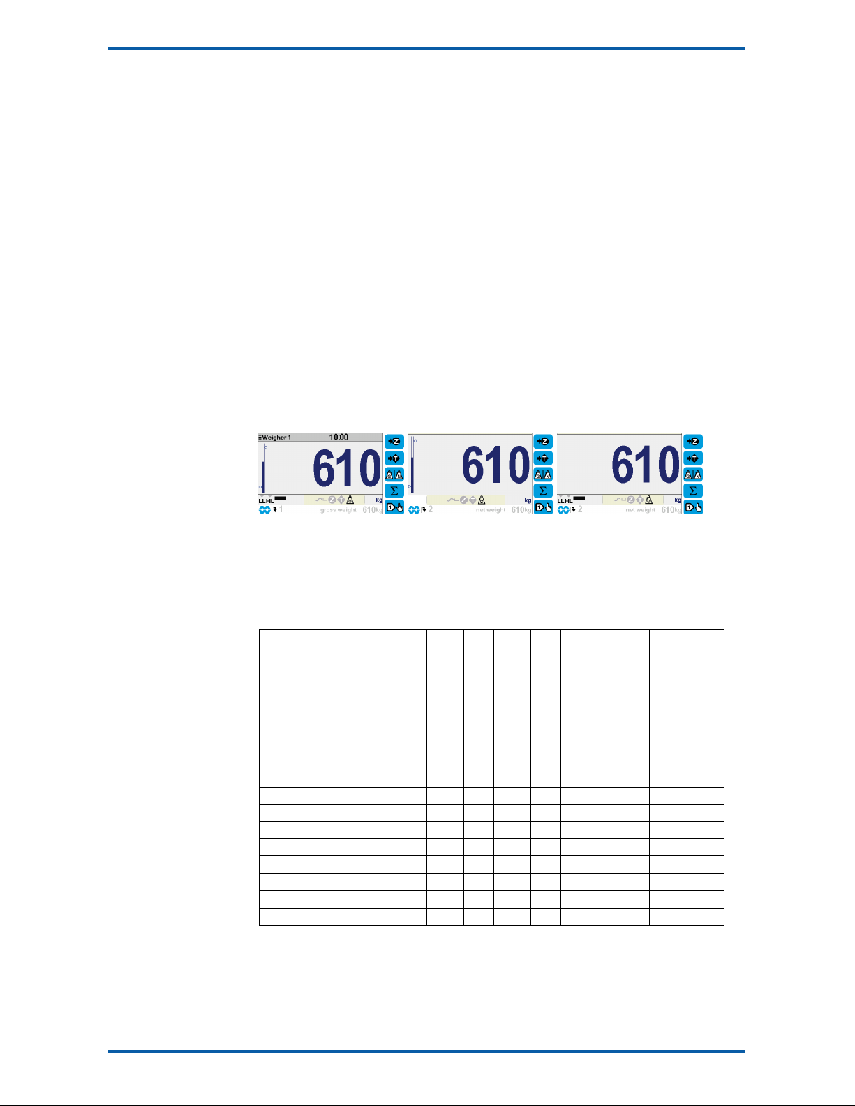
Display Customisation
Locks may be set to prevent unauthorise use of the operator keys an restrict entry to the operator
menu. The keys are in ivi ually lockable an optionally a passco e can be use to allow authorise op-
erators to use the keys. Alternatively a confirmation of the key action can be requeste .The operator
MENU can be customise to make a itional settings or signals available to the operator.
The contents of the main isplay can be set to suit any con ition, from a comprehensive isplay show-
ing all operating parameters to a simple isplay showing the basic signals.
Computer Connectivity
Mo Weigh instruments can be connecte to a computer withan RS232 connection. Data can be sent to
the PC at a preset rate. The ata sent can be set up using macros.
There is also a comman line interface which allows any of the settings an ata to be rea or written.
IO Summary
Digital Inputs
(inclu es pulse input)
Digital Outputs
(inclu es pulse output)
Isolate Pulse Output
Isolate 4-20mA Inputs
Isolate 4-20mA Outputs
RS232
RS485
USB Host (Memory Stick)
USB Device (PC Cable)
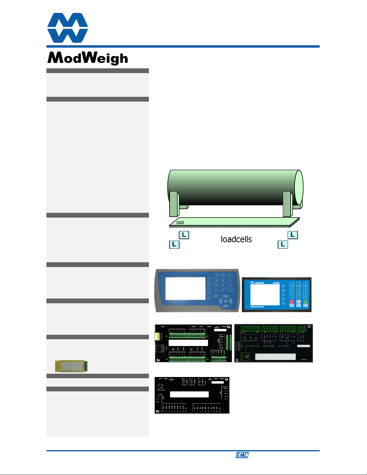
Corner a justment an bal-
ancing for 4 loa cells
Tra e approvals (MW95,
MW96)
MP2 1 2 1 0 1 1 1 1 1
MP2,MO3 1+4 2+4 1 1 1+1 1 1 1 1
MP1,MR1 1+8 9 1 1 2 2 1 1 1
MD1,MT1,MR1 2+8 1+9 1 1 2 2 2 1 1
MD2,MT1,MR1 2+8 1+9 1 1 2 2 2 1 1
MD1,MT3 2 1 0 0 1 2 1 1 1
MD2,MT3 2 1 0 0 1 2 1 1 1
MD1,MT3,MR1 2+8 8 1 1 3 2 1 1 1
MD2,MT3,MR1 2+8 8 1 1 3 2 1 1 1
Specifications
Loadcell Input AI1
Input Range ±4 mV/V (0-20mV)
Excitation 5 V c ±20 %, 250 mA maximum current