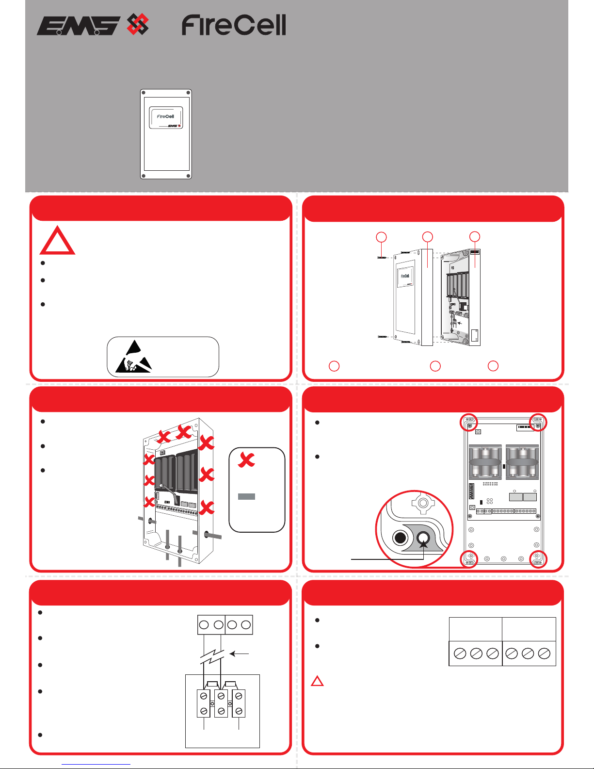
manuals.online logo
Brands
  1. Home
  2. •
  3. Brands
  4. •
  5. EMC
  6. •
  7. Smoke Alarm
  8. •
  9. EMC FC-610-001 User manual

EMC FC-610-001 User manual

©2015 EMS Security Group Ltd. All rights reserved Page 2 of 2 TSD050 Iss 12 09/02/2016 AJM
1 Pre Installation 2 Components
Part No Product Description
!
4x Lid Fixing Screws Front Lid
3
Back Box
5 Input Wiring
FC-610-001 Wireless Dual Input/Output Unit
Wireless Input Output Unit
Installation Guide
DUALI/O UNIT
FC-610-001
FC-610-001
DUALI/O UNIT
IDENT REV D ATE
FC-610-001
EN300 200-2
0359 !
20K 4K7
CN/O
20K = Red/Bl
4k7=Yellow
EOLResistor
Conguration
ANTENNA
2
1
3 Remove Cable Entry Points 4 Fix to the Wall
Use all four circled
fixing positions to
ensure a firm fixing.
Use suitable fasteners
and fixings.
INPUT 1 INPUT 2
IP- IP+ IP- IP+
20k 4k7
CN/O
Drill the cable entry
points as necessary.
Cable glands should
be used.
DO NOT leave
excess cable in the
device.
ON
INPUT1 INPUT2
EXPAN1 EXPAN2
OUTPUT 2
OUTPUT 1
IP- IP+ IP- IP+
3VDC SET RST
N/O COM N/C
3VDC SET RST
N/O COM N/C
Do Not Use
=
Available
Cable Entry
Points
=
Installation must conform to applicable local installation
codes and
should only be installed by a fully trained
competent person.
Ensure that the device is installed as per the site survey.
The use of a non-metallic spacer should be considered if
mounting the device on to a metal surface.
Do NOT Press the Log On button on a pre-programmed
device, as this will cause communication with the Control
Panel to be lost. Should this happen, delete the device from
the system and add it back on.
ATTENTION
OBSERVE PRECAUTIONS
FOR HANDLING
ELECTROSTATIC
SENSITIVE 123
ANTENNA
KEEP CABLES AWAY FROM THIS AREA
LOGON
OUTPUT 2OUTPUT 1
3VDC SET RST
INPUT 1 INPUT 2
LED
ENABLE
POWER
INPUT
INPUT
FAULT
CLOSED
0 1
1
64
F-SAFE
N/O COM N/C
IP- IP+ IP- IP+
3VDC SET RST N/O COM N/C
EXPAN1 EXPAN2
RELAY ON
RELAY ON
2
4
8
16
32
ON
1 2 3 4 5 6 7 8
012ABC
Fixing position
location within
cavity
6 Output Wiring
Two resistor monitored inputs are
available.
Both inputs monitor; closed (alarm),
open and short circuit conditions.
Each input is factory fitted with an
end of line 20kΩ resistor.
To connect inputs to external
devices, wire as shown below. I.e.
Input 1, using the resistor pack
provided.
If an input is not being used, leave
the 20kΩ resistor as factory fitted.
EOL
Resistor
Setup
Remote Monitored Device
Note: Max
Cable Length
of 10m
OUTPUT 2OUTPUT 1
N/O COM N/C N/O COM N/C
Two outputs are also available.
Both outputs are voltage
free and rated 2A @ 24Vdc.
WARNING. DO NOT CONNECT TO MAINS.
!
Page 2 of 2
7 Power Device
When fitting / replacing batteries; observe correct polarity,
using only specified batteries.
Connect the power jumper across the PIN header.
8 Configuration
Once powered, reassemble the device.
The device’s loop address is configured within the menu structure
of the Radio Hub.
Refer to the programming manual (Doc Ref: MK98) for full
programming information.
Free to download from
www.emsgroup.co.uk
OUTPUT 2OUTPUT 1
3VDC
SET RST
INPUT 1 INPUT 2
LED
ENABLE
PO WER
INPUT 1
INPUT 2
FA ULT
CLOSED
0 1
1
64
F-SAFE
N/O COM N/C
IP- IP+ IP- IP+
3VDC SET RST N/O COM N/C
EXPAN1 EXPAN2
RELAY ON
RELAY ON
2
4
8
16
32 device
unpowered
(pins unlinked)
device
powered
(both pins linked)
9 LED Operation
The device has six indication LEDs. Pressing the LED enable button
enables their illumination for 10 minutes before automatically
timing out.
2x Input Fault: YELLOW LED ON = FAULT
2x Input Closed: RED LED ON = ACTIVE
2x Output: RED LED ON = ACTIVE
CLOSED
FAU LT
INPUT 1
INPUT 2
Input 2
LEDs
Input 1
LEDs
Output 1 LED Output 2 LED
Operating
Temperature -10°C to 55°C
Storage
Temperature 5°C to 30°C
Humidity Up to 95% non-condensing
Supply 6x AA Alkaline (Panasonic LR6AD Powerline / Varta
4006 Industrial)
CAUTION!
Fitting of an incorrect battery type invalidates the product certification and
may result in poor performance.
Output rating 2A @ 24Vdc
IP Rating IP65
Operating Frequency 868MHz
Output Transmitter
Power Auto adjusting 0 - 14 dBm (0 - 25 mW)
Dimensions 270mm (W) 205mm (H) 75mm (D)
Weight 0.95kg
Location Type A: For indoor use
2012/19/EU (WEEE directive):
Products marked with this symbol cannot be
disposed of as unsorted municipal waste in the
European Union. For recycling, return this product to
your local supplier upon purchase of equivalent new
equipment, or dispose of it at designated collection
points. For more information see
www.recyclethis.info
Dispose of your batteries in an environmentally
friendly manner according to your local regulations.
European Union
directives
EMS Security Group Ltd hereby declares that this
device is in compliance with the essential
requirements and other relevant provisions of
Directive 2014/53/EU (R&TTE directive).
Approved to EN54-18:2005. Fire detection and fire alarm
systems. Part 18: Input/output devices.
EN54-25:2008. Incorporating corrigenda
September 2010 and March 2012. Fire detection
and fire alarm systems. Part 25: Components using
radio links.
Certification
Certification body
CPR Certificate DOP 0359-CPR-0039
EMS Security Group Ltd. Technology House, Herne
Bay, Kent, CT6 8JZ, United Kingdom
Manufacturer
Year of
manufacture See devices serial number label
0359
10
Specification Regulatory Information

Popular Smoke Alarm manuals by other brands

usi MIC1509S manual

usi

usi MIC1509S manual

Smartwares RM620 user manual

Smartwares

Smartwares RM620 user manual

ELRO PS4910 instruction manual

ELRO

ELRO PS4910 instruction manual

U-Line H-9471 manual

U-Line

U-Line H-9471 manual

Smanos SMK-500 user manual

Smanos

Smanos SMK-500 user manual

Nemaxx FL10-VdS Original operating instructions

Nemaxx

Nemaxx FL10-VdS Original operating instructions

Silent Alert UM3A-2212-EU-PSU quick start guide

Silent Alert

Silent Alert UM3A-2212-EU-PSU quick start guide

x-sense XS03 user manual

x-sense

x-sense XS03 user manual

Teletek electronics SensoMAG S30 Installation instruction

Teletek electronics

Teletek electronics SensoMAG S30 Installation instruction

Kidde KI-PCD Installation sheet

Kidde

Kidde KI-PCD Installation sheet

Visonic WST-400 installation instructions

Visonic

Visonic WST-400 installation instructions

Simplex MINIPLEX 4100ES Series installation guide

Simplex

Simplex MINIPLEX 4100ES Series installation guide

Cavius 2208 installation guide

Cavius

Cavius 2208 installation guide

Metasys 2251J manual

Metasys

Metasys 2251J manual

SMC Networks SMCSM01-Z user manual

SMC Networks

SMC Networks SMCSM01-Z user manual

Bosch FAP-OT 420 KKW manual

Bosch

Bosch FAP-OT 420 KKW manual

Siemens TITANUS SuperSens Quick Guide for Commissioning

Siemens

Siemens TITANUS SuperSens Quick Guide for Commissioning

FCI System Sensor 2151 user manual

FCI

FCI System Sensor 2151 user manual

manuals.online logo
manuals.online logoBrands
  • About & Mission
  • Contact us
  • Privacy Policy
  • Terms and Conditions

Copyright 2025 Manuals.Online. All Rights Reserved.