Use Celerra Startup Assistant
3f Power Cables
4
Powering Down Your Celerra NS40
4
3e External Network Cables
1. If no components other than the NS40 are in the cabinet, turn off the cabinet circuit breakers.
Otherwise leave them on.
2. Turn off your standby power supply (SPS) power switch.
3. Connect the disk-array enclosure power supply A to the SPS A power distribution panel (PDP).
4. Connect the disk-array enclosure power supply B to the left PDP.
5. Connect SPS A to the right PDP.
6. Connect storage processor enclosure A to SPS A.
7. Connect storage processor enclosure B to the left PDP.
8. Connect the power cable from the right side of the Control Station to the right PDP.
9. Connect the two 240-volt AC power cables from the cabinet to your power outlets. If possible,
connect each cable to a different circuit.
10. Turn on all circuit breakers on each of the cabinet’s power strips.
11. Turn on the SPS power switch.
12. Connect blade enclosure A to the right PDP.
13. Connect blade enclosure B to the left PDP.
14. Verify each component has power (LED illuminated). After a few minutes, each component should
have a green LED, except for the storage processor enclosure. The storage processor enclosure
powers up and is fully booted within a few minutes. The enclosure warning light will not extinguish
until the SPS battery is fully charged. This may take 15 minutes.
1. Remove the tear away label on the front of the Control Station. You need this for the Celerra Startup Assistant.
2. Insert the Celerra Network Server Applications and Tools CD into the client computer. EMC Product Installation window opens.
3. Click Celerra Startup Assistant and use the InstallShield to install the Celerra Startup Assistant on the client computer.
4. Double-click the Celerra Startup Assistant shortcut on the desktop or go to C:\ProgramFiles\EMC\CSA\startup\launch.bat to run the
Celerra Startup Assistant. The Celerra Startup Assistant guides you through the remaining steps.
Note: This system must be registered before the client can receive service. If the registration is not done as part of the CSA,
the customer may use the registration wizard to register the system. Go to C:\ProgramFiles\EMC\RegWiz\Register.bat
5. After the Celerra Startup Assistant
, nishes with the basic installation, use the Celerra Manager to create a customized conguration of the
Celerra NS40 system.
Refer to
http://Powerlink.EMC.com (select Celerra Tools in the Navigator and select NS40 Integrated >Installation Overview)
for completing your installation.
1. Do the following before you power down the Celerra NS40:
a. Notify all users of the planned powerdown several days in advance when possible.
b. Inhibit all logins and notify all users several minutes in advance of the impending powerdown.
c. Log out all users.
2. Log in to the Control Station as root, using a Telnet or SSH session. To perform a planned powerdown,
you must be within close proximity to the server.
3. To halt the Celerra server, type:
# /nasmcd/sbin/nas_halt now
ARE YOU SURE YOU WANT TO CONTINUE? [ yes or no ] :
# yes
Sending the halt signal to the Master Control Daemon...: Done
.
.
Halting system...
flushing ide devices: hda hdd
Power down.
It can take as long as 20 minutes to halt the server, depending on the number of blades and
the size of the database. Wait until the command completes before continuing.
4. Disconnect the blade enclosure power cords from the power distribution units (PDUs).
5. Turn off (0 position) the power switch on the standby power supplies (SPSs) and wait at least 1 minute to
allow the storage system to write its cache to disk.
Make sure the supply’s power indicator is off before continuing.
6. Disconnect the DAE3P power cords from the PDU.
7. If no components other than the NS40 are in the cabinet, turn off the cabinet circuit breakers.
Otherwise leave them on.
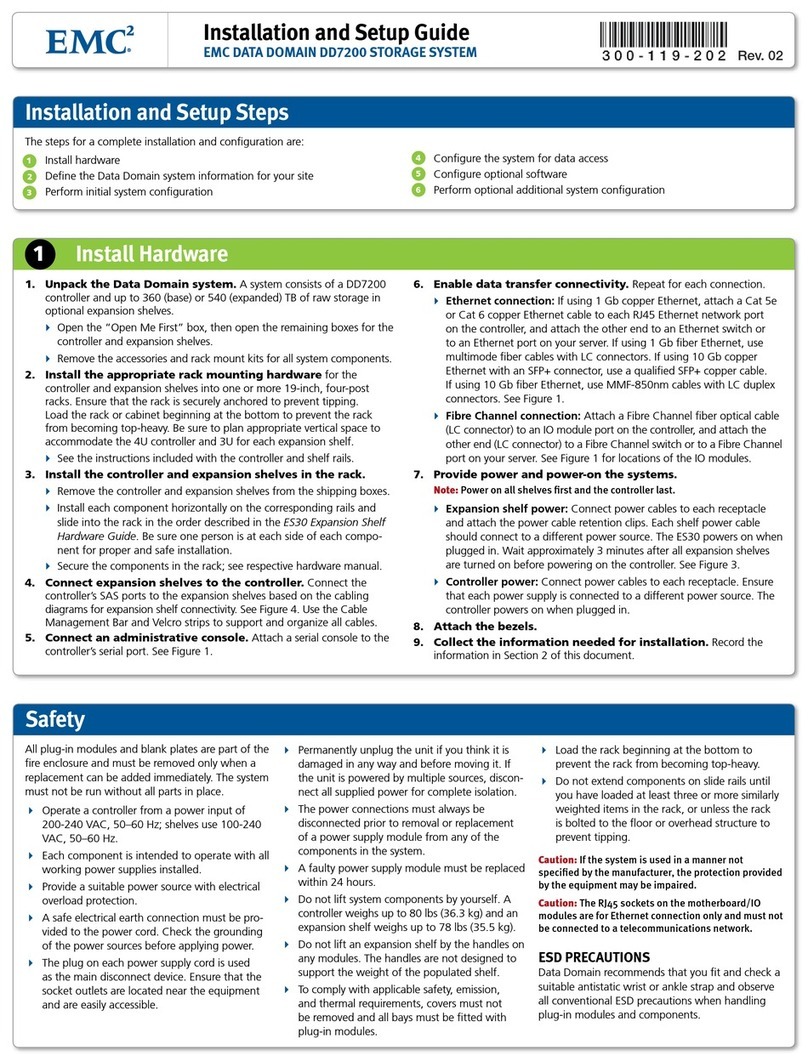
Required parts:
•
Celerra Network Server Applications and Tools CD
• Windows-based client computer on the same subnet (customer network) as the NS40 management Control Station. You must have
100 MB of free space on the client PC. The client computer should have access to the Internet.
B
A
!
!
!!
!
EXP PRI
EXPPRI
#
!
EXP PRI
EXPPRI
#
A
B
Standby power supply (SPS)
Disk-array enclosure
SP A
CIP-000912
Blade enclosure
SP B
Control Station
Blade 3 Blade 2
To public LAN
To public LAN
To public LAN MGMT
cge0 cge1 cge2 cge3
Storage processor
enclosure
B
A
!
!
!!
!
EXP PRI
EXPPRI
#
!
EXP PRI
EXPPRI
#
A
B
Standby power supply (SPS)
Disk-array enclosure
SP A
CIP-000913
SP B
Control Station
Blade 3 Blade 2
To public LAN
To public LAN
To public LAN MGMT
fge0 fge1 cge0 cge1
Storage processor
enclosure
CIP-000943
ON
I
OFF
O
ON
I
OFF
O
ON
I
OFF
O
ON
I
OFF
O
B
A
!!
!!
!
EXP PRI
EXPPRI
#
!
EXP PRI
EXPPRI
#
A
B
Standby power
supply (SPS)
Blade 3 Blade 2
Control Station
Storage
processor
enclosure
SP B
Blade
enclosure
SP A
Disk-array
enclosure
PDP
ON
I
OFF
O
!!
#
!
EXP PRI
EXPPRI
Required cables:
• Ethernet cable:
• Two copper Ethernet cables (customer-provided)
NOTE: Attach customer provided Ethernet cables from customer
external LAN to blade public (cge) ports.
MGMT
CIP-000900
ON
I
OFF
O
ON
I
OFF
O
ON
I
OFF
O
ON
I
OFF
O
ON
I
OFF
O
ON
I
OFF
O
!!
!!
!
EXP PRI
EXPPRI
#
!
EXP PRI
EXPPRI
#
A
B
!!
!!
!
EXP PRI
EXPPRI
#
!
EXP PRI
EXPPRI
#
A
B
!!
!!
!
EXP PRI
EXPPRI
#
!
EXP PRI
EXPPRI
#
A
B
!!
!!
!
EXP PRI
EXPPRI
#
!
EXP PRI
EXPPRI
#
A
B
B
A
Standby power supply (SPS)
Blade 3
Blade 2
Control Station
Storage processor
enclosure
SP B
Blade enclosure
SP A
Disk-array enclosure
Disk-array enclosure (optional)
Disk-array enclosure (optional)
Disk-array enclosure (optional)
