Emcee SR-200D User manual

SR-200D
Professional HD
Integrated Receiver Decoder
User Manual
EMCEE COMMUNICATIONS
2546 West Birchwood Avenue, Mesa, Arizona 85281 USA

V1.02-N

1
Preface
About This Manual
This manual provides introduction to users about how to operate the device correctly. The
content includes introduction to product installation, product characteristics and product
settings, etc. It is highly suggested that users should read this document before actually
operating the device.
Intended Readers
This manual is suggested to be studied by the following readers:
lTechnical Service Engineer
lMaintenance Engineer
lTest Engineer
lSales Engineer
Symbols Definition
For the symbols that might appear in this document, the meanings they represent are as the
following:
Symbol
Meaning
There is highly potential danger. If it cannot be avoided, it will lead to the deaths or
serious injury.
There is medium or low potential danger. If it cannot be avoided, it will lead to medium
or slight injury.
There are potential risks. If ignore these texts, it may cause damage to the device,
data loss, equipment performance reduce or unpredictable results.
Tips that help you to solve problems or save your time.
Remarks. Additional information to the text, in order to emphasize something.

2
Contents
1About This Product...........................................................................................................4
1.1Introduction.................................................................................................................4
1.2 Safety .........................................................................................................................4
1.3 Architecture ................................................................................................................5
1.4 Methods of Operation.................................................................................................6
1.4.1 Operation through WEB UI.............................................................................6
1.4.2 Operation through Front Panel Operation......................................................7
1.5 Technical Specifications.............................................................................................7
1.5.1 Physical Specifications ....................................................................................7
1.5.2 Performance and Capacity..............................................................................8
1.5.3 Interfaces and Protocols..................................................................................8
2Installation ..................................................................................................................... 10
2.1 Installation Procedure ............................................................................................. 10
2.2 Preparation before Installation................................................................................ 10
2.3 Check Package and Accessories.............................................................................11
2.4 Equipment Wiring and Connection ..........................................................................11
2.4.1 Connection Setup for RF Signal Input.......................................................... 12
2.4.2 Connection Setup for ASI signal input.......................................................... 12
2.4.3 Connection Setup for IP signal input............................................................ 12
3Operation Guide............................................................................................................ 13
3.1Operation Overview................................................................................................. 13
3.2Powering Up and Initialization ................................................................................. 13
3.3Front Panel Operation ............................................................................................. 13
3.3.1 Front Panel Menu Structure.......................................................................... 14
3.3.2 Front Panel Operation Guide........................................................................ 16
3.4WEB UI Operation (Recommended)....................................................................... 17
3.4.1 WEB Management Connecting .................................................................... 17
3.4.2 Parameters Configuration............................................................................. 19

3
3.5Preparation before Officially Operation ................................................................... 36
3.5.1 Clear all useless data.................................................................................... 37
3.5.2 Configure the equipment with working data................................................. 37
3.5.3 Full checking before implementation............................................................ 37
4FAQ ............................................................................................................................... 38
5Terminology................................................................................................................... 40

4
1
About This Product
1.1Introduction
This product is a new generation integrated receiver decoder to support the growing
demands for multi-format, multi-standard video delivery and distribution. It can receive
digital signals from several inputs (DVB-S/S2, DVB-C (optional), DVB-T/T2/ISDB-T (optional)
and ASI), decrypt and process/select programs to various outputs including CVBS, HDMI,
SD/HD SDI and ASI. It supports multi-channel descrambling, multiplexing, external
table/data insertion, transcoding and transmodulating. It also supports video decoding with
two audio channels. With remote web-based management interface, it is ideal to support
advanced application such as content distribution, real-time signal conversion and
transmission.
1.2 Safety
lTo avoid electric-shock hazards, do not open the receiver; refer service to qualified
personnel only.
lDo not expose the device in the sunlight, and keep it away from the heat source.
lDo not block ventilation holes of the device so that air can circulate freely.
lSwitch the device off whenever it remains out of service for an extended period.
lBe sure to turn the device off and disconnect the AC power cord before cleaning the
receiver surface.
lThe apparatus shall be connected the mains socket outlet with a protective earthing
connection
lThe appliance coupler used as the disconnect device shall remain readily operable.
lThis product has gone through regulated EMC test and meets with EMC safety
requirement.
( Such tests are conducted in a controlled EMC environment. A controlled
EMC environment exists in a building where the installation has been designed
5
having special regards to EMC, and where technical personnel are present with
experience of EMC technology.)
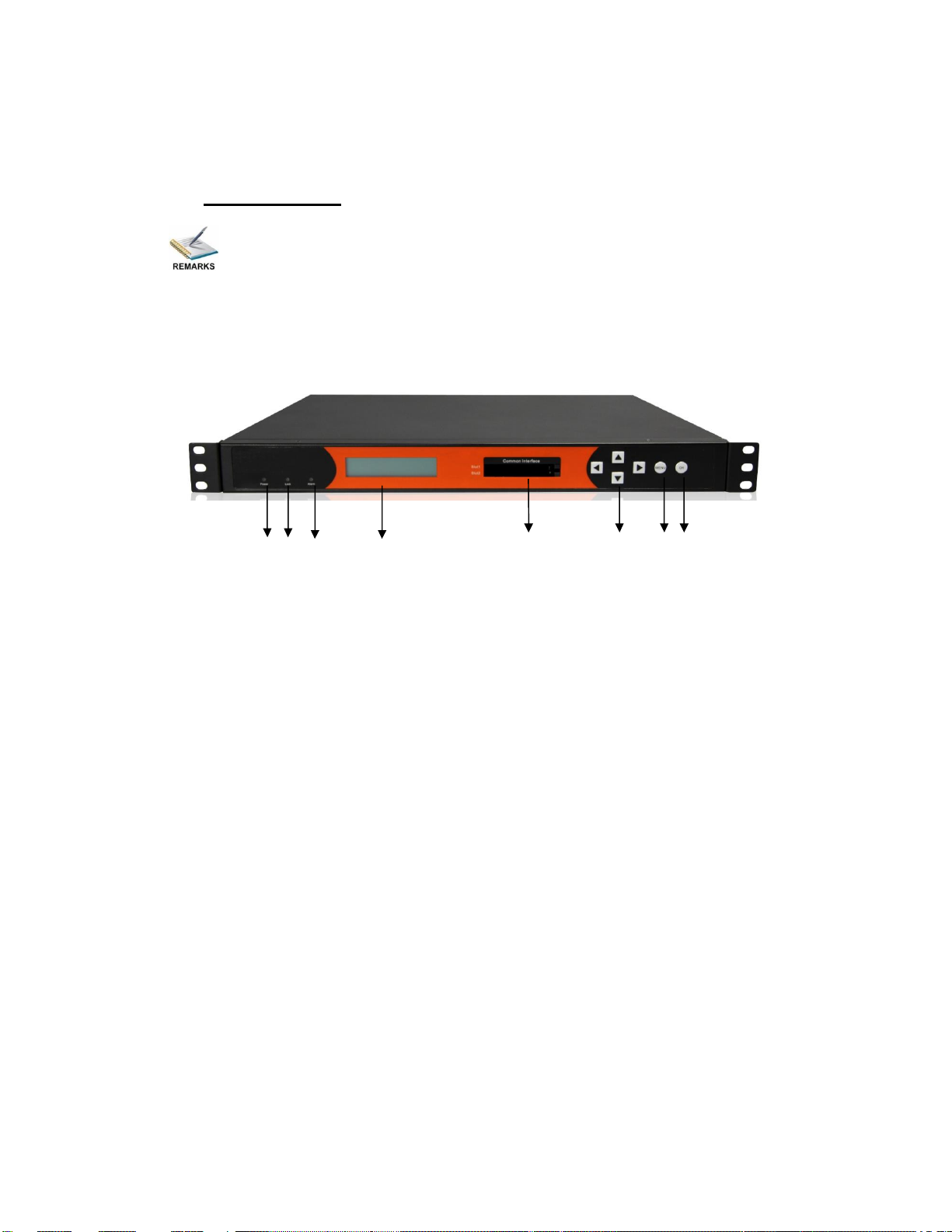
1.3 Architecture
The equipment of this section is shown in schematic diagram. It is subject
to change for improvement on the real product without advanced notice.
Front Panel
1 2 3 4 5 6 7 8
PIC-1.3-1
1. Power status indicator: This LED light is turned on when the IRD is power on.
2. (Signal) Lock status indicator: This LED light is turned on when a channel is locked.
Otherwise there is no channel locked.
3. Alarm status indicator: This LED flickers when there is something abnormal. For
example, the strength of the input signal is too weak.
4. Display screen: This LCD screen can show the program and configuration information.
5. CI SLOTS: There are two CI slots for various CAS CAM (PCMCIA) modules.
6. KEY PADS:
lUp/Down/Left/Right arrow keys: To change channels, to adjust volumes and
configure the IRD.
lMenu: To enter the menu and the quit function of the sub menus.
lOK: To confirm the operation in the setup.

6
Rear Panel
1 2 3 4 5 6 7 8 9 10
11 12 13 14 15 16 17 18 19 20 21 22
PIC-1.3-2
1 GPI/LS DATA Out 2 CVBS Out
3 R-AUDIO1 4 R-AUDIO2
5 ASI OUT2 6 ASI IN2
7 RF OUT2 8 RF IN2
9 RF Out1 10 RF IN1
11 BALANCED AUDIO OUT 12 HDMI
13 SDI OUT 14 L-AUDIO1
15 L-AUDIO2 16 ASI OUT1
17 ASI IN1 18 MANAGEMENT
19 TS/IP 20 TS/IP (Redundant)
21 POWER CORD IN 22 POWER SWITCH
Redundant POWER (Optional)
1.4 Methods of Operation
1.4.1 Operation through WEB UI
Operate the IRD remotely through WEB UI. The WEB UI operation supports:
Functions Description Related Items
Parameters
Setting
WEB UI allows users to
conduct operations of
parameters
configuration,
modification and setup.
Signal receive setup
CI setup
Decoder setup
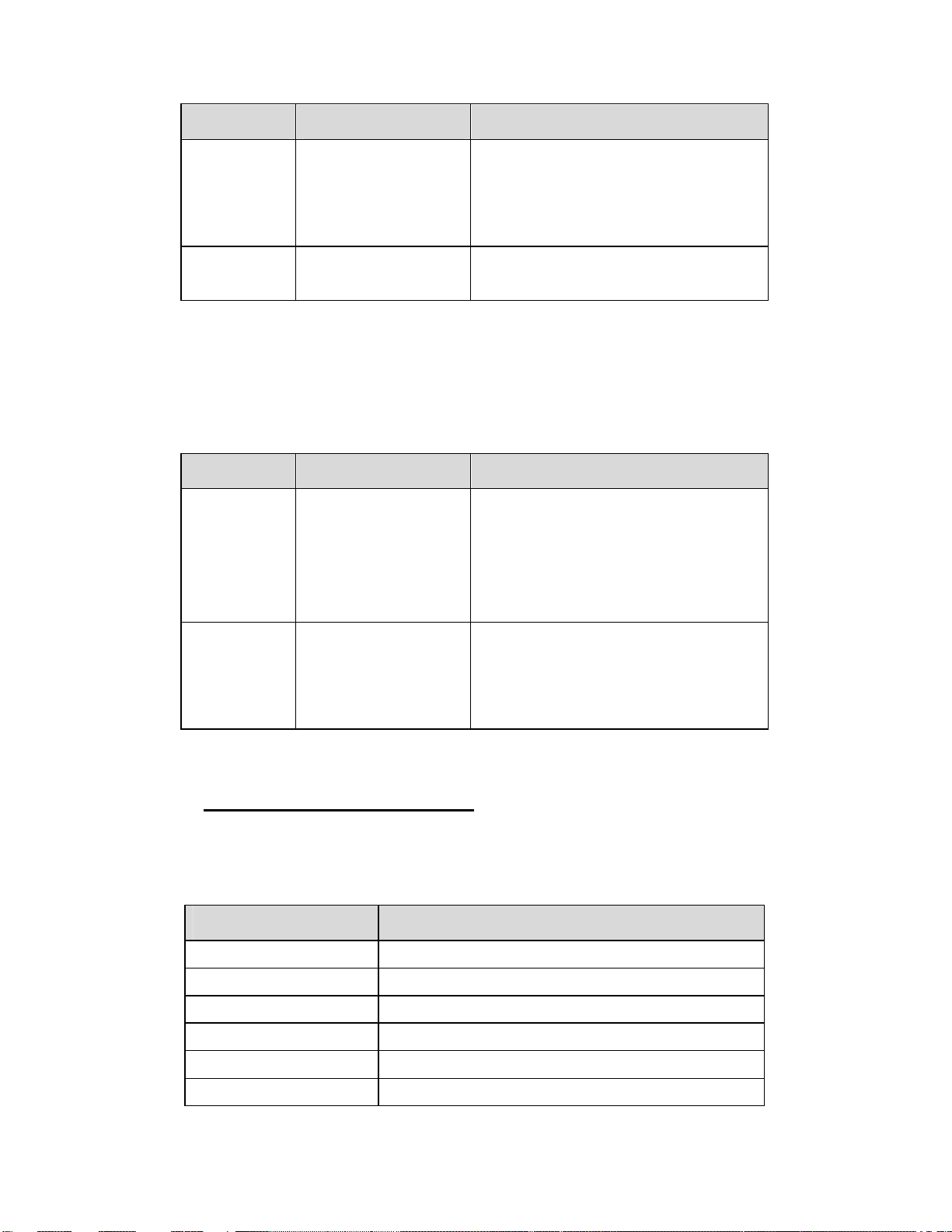
7
Functions Description Related Items
Status
Monitoring
Support real-time
monitoring on running
status of input signal,
CI descrambling, etc.
RF signal strength indication
CI slot/CAM information
HW/SW version information
Upgrade
Support unit upgrade
through WEB UI
1.4.2 Operation through Front Panel Operation
Operation through front panel control buttons; users can configure all the parameters as the
followings:
Functions Description Related Items
Parameters
Setting
Allows users to
conduct operations of
parameters
configuration,
modification and setup.
Signal receive setup
CI setup
Decoder setup
Status
Monitoring
Support real-time
monitoring on running
status of input signal,
CI descrambling, etc.
RF signal strength indication
CI slot/CAM information
HW/SW version information
1.5 Technical Specifications
1.5.1 Physical Specifications
Items Index
Power AC100~240VAC
Max. Power Consumption Approx 40W
Size
1RU
Dimension
48
0
mm (
W
) ×
4
4mm (
H)
× 44
0
mm (
D
)
Net Weight Approx 3.8Kg
Gross Weight Approx 5Kg
8
1.5.2 Performance and Capacity
Items Index
ASI Max. Input Bitrate 100Mbps
ASI Max. Output Bitrate 100Mbps
Decoder Max. Resolution 1920 X 1080i
CI Max. Output Bitrate
100Mbps
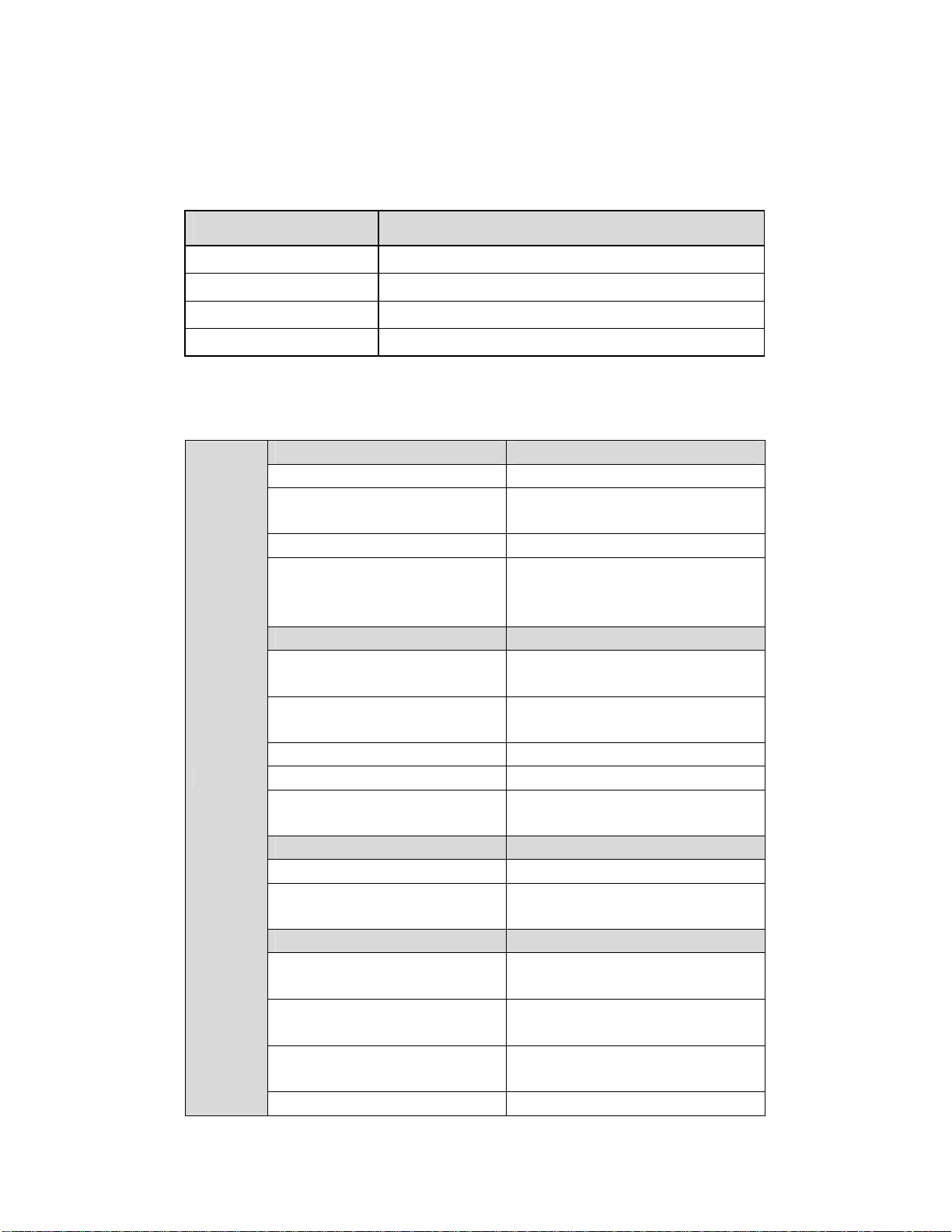
1.5.3 Interfaces and Protocols
Inputs
IP input ASI input
Interface: 1 x 1000 Mbps Interface: 2 ASI inputs, 75Ω
IP Encapsulation: UDP/RTP MPEG Format: 188/204 Bytes per
TS
MPEG TS: MPTS and SPTS Max bit rate: 100 Mbps
Input processing: Up to 2
channels, max at 72 Mbps per
channel. Support input redundancy.
DVB-T2 (Optional) DVB-T (Optional)
Constellation: 16/32/64/128/256
QAM Constellation: QPSK/16/64QAM
Bandwidth: 1.7Mhz, 5Mhz,
6Mhz, 7Mhz, 8Mhz, 10Mhz Bandwidth: 6/7/8Mhz
Input frequency: 48~862MHz Input frequency: 48~862MHz
Max. bitrate: 50Mbps Max. bitrate: 31.67Mbps
Transmission mode: 1K, 2K, 4K,
8K, 16K, 32K Transmission mode: 2K, 8K
DVB-S/S2 DVB-C (Optional)
Input Frequency: 950~2150 MHz
Frequency: 48~862 MHz
Constellation: QPSK, 8 PSK Constellation: 16/32/64/128/256
QAM
ISDB-T/Tb (Optional) ATSC (Optional)
Constellation: QPSK/16/64QAM
DQPSK Constellation: 8VSB
Bandwidth: 1.7Mhz, 5Mhz,
6Mhz, 7Mhz, 8Mhz, 10Mhz Bandwidth: 6Mhz
Input frequency: 48~862MHz Input frequency: 57~803MHz
(fixed)
Transmission mode: 1K, 2K, 4K, Max bitrate: 19.39Mbps
9
8K, 16K, 32K
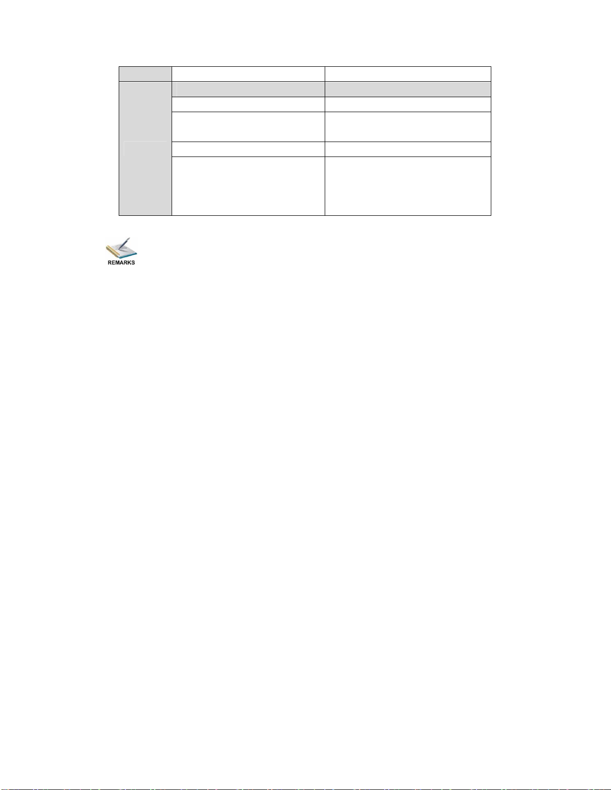
Outputs
IP output ASI output
Interface: RJ45 Interface: 2 ASI outputs, 75Ω
IP Encapsulation: UDP/RTP MPEG Format: 188/204 Bytes per
TS
MPEG TS: MPTS and SPTS Max bit rate: 100 Mbps
Output processing: Up to 2
channels, max at 72 Mbps per
channel, support TS/IP
redundancy.
The physical connector design is subject to change without advanced notice
(either the connector type or specific connector location) according to user’s specific
order, performance improvement, or for better user experience.
10
2 Installation
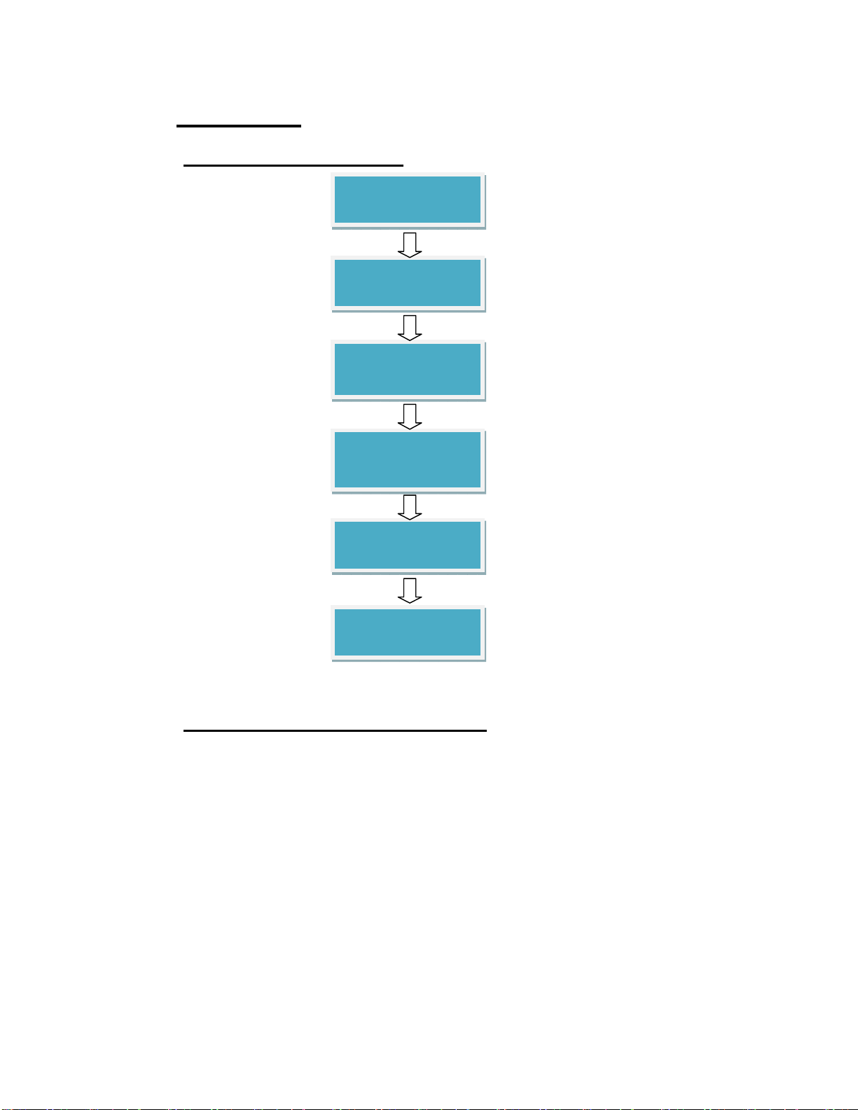
2.1 Installation Procedure
2.2 Preparation before Installation
Before installation, the installation personnel should read through and confirm the
followings:
·Go through this user manual.
·Has the knowledge of digital television system.
·Has defined the sources, racks allocation, and set-up plan system wiring.
·Knows how to operate this unit and parameters configuration.
·Go through related engineering design documents about the system.
Preparation before
Installation
Check Package
and Accessories
Setup Connection
(signals, wiring)
Parameters
Configuration
System Debug
Finish
11
2.3 Check Package and Accessories
The IRD package includes the following accessories:
lBase Unit x1
lPower cord x1
lEarth cord x1
lBNC cord x1
lBNC-RCA cord x2
lUser Guide Disc x1
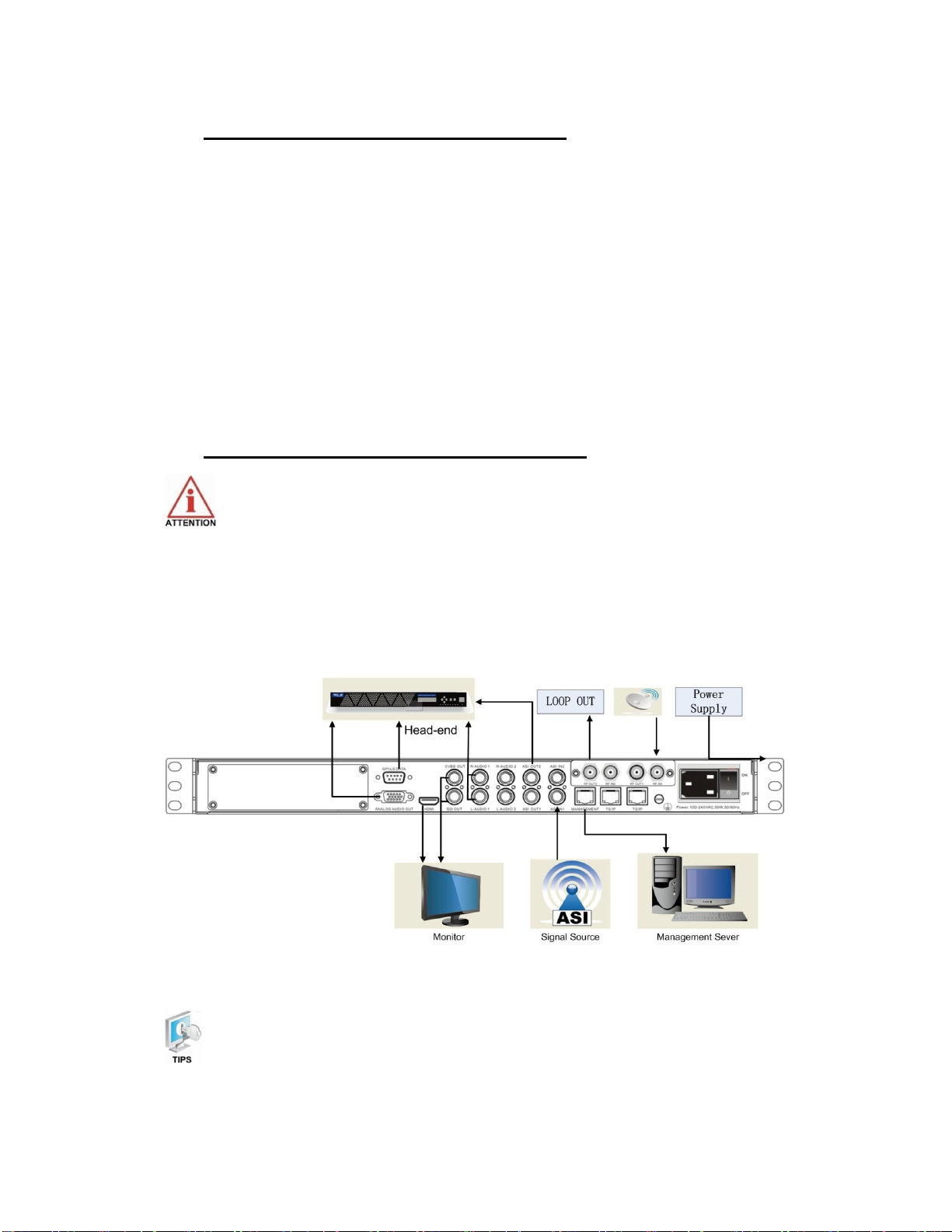
2.4 Equipment Wiring and Connection
To avoid electric shock and damage to the equipment, before setting up the
wiring connection, please power off the equipment and all other connected external
devices. The equipment and external devices must be grounded. Powering on the
equipment only after all the wiring connection is completed.
Connection Diagram
PIC-2.4-1
In actual application, not all connection interfaces need to be connected with
signal/external devices. Please connect according to actual application purpose.

12
To ensure a smooth communication between the management PC and the
IRD, please try to connect the IRD management port to a switch without large data
processing.
2.4.1 Connection Setup for RF Signal Input
lConnect signal to tuner input (either RF1 or RF2 input) with a RF cable.
lConnect the IRD “Management”port to a switch, set up a management network with
the management PC.
lConnect the IRD with the monitor via HDMI, SDI or CVBS ports.
2.4.2 Connection Setup for ASI signal input
lConnect ASI signal to IRD “ASI IN”port with a BNC cable.
lConnect the IRD “Management”port to a switch, set up a management network with
the management PC.
lConnect the IRD with the monitor via HDMI, SDI or CVBS ports.
2.4.3 Connection Setup for IP signal input
lConnect IP signal to IRD “TS/IP”port with a twisted cable.
lConnect the IRD “Management”port to a switch, set up a management network with
the management PC.
lConnect the IRD with the monitor via HDMI, SDI or CVBS ports.

13
3 Operation Guide
3.1. Operation Overview
This chapter provides information on how to operate the IRD through front panel and WEB
UI. User can select the most proper operation method to set up the unit.
3.2. Powering Up and Initialization
Switch on the equipment through the rear power switch, and the unit is powered up and
starts the initialization.
The LCD screen is lighted up, and display information as following:
The initialization takes about 20 seconds to complete, and then the IRD shows the IP
address information as following:
Before powering-up the device, make sure that all cabling is correctly
connected (refer to chapter 3.4 of this manual). The device is correctly connected to
the power inlet and grounded.
If the unit fails to initialize and hangs at the “booting”stage, switching off the
device and then powering up again may help. If the device still fails to initialize,
please contact your service representative for help.
3.3. Front Panel Operation
Ways of operation: use the 6 navigation keys on front panel: Up / Down / Left / Right / Menu /
Ok to configure the IRD parameters. The configuration and settings are displayed through
front panel LCD.
H.264 SD/HD IRD
IP: 192.168.001.098
H.264 SD/HD IRD
Setting System…

14
3.3.1 Front Panel Menu Structure
Front Panel Menu Structure
1st Layer 2nd Layer 3rd Layer
Status
Input Tuner 1/2
Lock Status
FEC
PER
Frequency Offset
Frequency Tune
TS Rate
RF Level
C/N
BER
Input ASI 1/2 Lock Status
TS Rate
Input IP 1/2 Lock Status
TS Rate
Decoder
TS Rate
PCR PID
Audio PID
Video PID
PMT PID
Program No.
CI CI Slot 1/2
Output ASI ASI 1 TS Rate
ASI 2 TS Rate
Output IP IP 1 TS Rate
IP 2 TS Rate

15
Inputs
Tuner 1/2 Tuner 1/2 Params
Enable
TS Standard
LNB Frequency
Satellite Frequency
Symbol Rate
LNB Power Supply
LNB 22KHz
Scan TS
ASI 1/2
Enable
TS Standard
Scan TS
IP Local Setting
TSIP Channel 1/2
Outputs
Decoder
Playing Program TS Source
Program List
Video
Video Standard
Aspect Ratio
Video Format
Audio
Audio Volume
Audio Mixer
Audio 1/2 Language
Subtitle Subtitle Standard
Teletext Teletext Standard
ASI ASI 1/2 TS Source
Tuner 1/2
Mux 1/2
ASI 1/2
IP TSIP Channel 1/2 Enable
TS Source

16
Dest IP Address
Dest Port
Protocol
Time to Live
TS Packet Number
Enable Dest MAC
Dest MAC
CA
Common Interface CI 1/2 TS Source
Descrambling
CAM Max Bitrate
BISS Setting BISS Setup
BISS Mode
BISS-1 Setup
BISS-E Setup
System Local Setup
Local IP Address
Local Network Mask
Local Gateway
MAC Address
Version
Factory Setting
Reboot
3.3.2 Front Panel Operation Guide
·Enter “Menu”:
oPress “MENU”button to enter main menu.
·Exit Menu/Back to parent Menu
oUpon completion of configuration settings, press “MENU”button until you
go back to the Parent Menu.

17
·Enter Sub-Menu
oPress MENU button to enter main menu.
oSelect a sub-menu by pressing arrow UP and arrow DOWN button.
oPress OK button on the selected sub-menu.
·To change parameter
oStep 1: Enter main menu by pressing MENU button.
oStep 2: Scroll sub-menu by pressing arrow UP and arrow DOWN button,
and press OK button to change the selected sub-menu.
oStep 3: To change parameter settings, press arrow RIGHT and arrow LEFT
button to move the cursor in which change must be made.
oPress arrow UP button and arrow DOWN to input / select an appropriate
setting, then press OK button to save.
3.4. WEB UI Operation (Recommended)
Accessing the equipment via Web can be very convenient for remote configuration of the
equipment. Relative to the front panel settings WEB operation can provide a friendlier
man-machine interface, and with less limits in space. WEB Management is recommended.
3.4.1 WEB Management Connecting
Connection Instruction:
PIC-3.4-1
1. Connect the “MANAGEMENT”port of the IRD to a network switch and connect the
management PC/server to the same network switch.
2. The IRD default IP address is 192.168.1.98. It is important to set the IP address of

18
the IRD and the monitoring severs in the same section to ensure a smoothly
connection between them.
3. Open a web browser (e.g. Mozilla, internet explorer, safari and etc.), enter the
equipment’s IP address in format: http://xxx.xxx.xxx.xxx (xxx.xxx.xxx.xxx refers to
IRD’s IP address) and press ENTER button to confirm. The browser will attempt to
connect to the device. If succeed, a login page will appear. (see PIC-3.4.2)
Note: Through WEB browser, you can manage several pieces of HD IRD at the
same time, as long as those equipments are connected to the server via Network
Switch. Make sure that the equipment and server’s IP address should be in the
same section. Nevertheless, Subnet Mask and Gateway should be the same for
both the server and the equipment.
PIC-3.4-2
lTo login, you need to enter the default username “admin”and password “admin”.
Then click “Submit”.
lIf the user name and password is correct, it will redirect to the main page.
Table of contents


